EP0683604A2 - Abschaltvorrichtung für Empfänger eines komprimierten Video-/Audiosignals - Google Patents
Abschaltvorrichtung für Empfänger eines komprimierten Video-/Audiosignals Download PDFInfo
- Publication number
- EP0683604A2 EP0683604A2 EP95107007A EP95107007A EP0683604A2 EP 0683604 A2 EP0683604 A2 EP 0683604A2 EP 95107007 A EP95107007 A EP 95107007A EP 95107007 A EP95107007 A EP 95107007A EP 0683604 A2 EP0683604 A2 EP 0683604A2
- Authority
- EP
- European Patent Office
- Prior art keywords
- signal
- audio
- video
- pts
- synchronization
- Prior art date
- Legal status (The legal status is an assumption and is not a legal conclusion. Google has not performed a legal analysis and makes no representation as to the accuracy of the status listed.)
- Granted
Links
- 230000005236 sound signal Effects 0.000 claims description 25
- 238000001514 detection method Methods 0.000 claims description 6
- 230000006837 decompression Effects 0.000 claims description 3
- 239000002131 composite material Substances 0.000 claims 1
- 239000000872 buffer Substances 0.000 description 12
- 230000006870 function Effects 0.000 description 8
- 230000001360 synchronised effect Effects 0.000 description 8
- 230000015654 memory Effects 0.000 description 7
- 230000005540 biological transmission Effects 0.000 description 5
- 238000010586 diagram Methods 0.000 description 4
- 230000000694 effects Effects 0.000 description 4
- 238000005070 sampling Methods 0.000 description 4
- 238000006243 chemical reaction Methods 0.000 description 3
- 230000006835 compression Effects 0.000 description 3
- 238000007906 compression Methods 0.000 description 3
- 230000033001 locomotion Effects 0.000 description 3
- 230000007774 longterm Effects 0.000 description 3
- 230000008520 organization Effects 0.000 description 3
- 230000001143 conditioned effect Effects 0.000 description 2
- 230000036039 immunity Effects 0.000 description 2
- 238000000034 method Methods 0.000 description 2
- 230000008054 signal transmission Effects 0.000 description 2
- 230000002123 temporal effect Effects 0.000 description 2
- 101000969688 Homo sapiens Macrophage-expressed gene 1 protein Proteins 0.000 description 1
- 102100021285 Macrophage-expressed gene 1 protein Human genes 0.000 description 1
- 230000001594 aberrant effect Effects 0.000 description 1
- 230000001934 delay Effects 0.000 description 1
- 230000008030 elimination Effects 0.000 description 1
- 238000003379 elimination reaction Methods 0.000 description 1
- 238000004519 manufacturing process Methods 0.000 description 1
- 239000000463 material Substances 0.000 description 1
- 230000007246 mechanism Effects 0.000 description 1
- 238000010606 normalization Methods 0.000 description 1
- 239000013641 positive control Substances 0.000 description 1
Images



Classifications
-
- H—ELECTRICITY
- H04—ELECTRIC COMMUNICATION TECHNIQUE
- H04N—PICTORIAL COMMUNICATION, e.g. TELEVISION
- H04N21/00—Selective content distribution, e.g. interactive television or video on demand [VOD]
- H04N21/40—Client devices specifically adapted for the reception of or interaction with content, e.g. set-top-box [STB]; Operations thereof
- H04N21/43—Processing of content or additional data, e.g. demultiplexing additional data from a digital video stream; Elementary client operations, e.g. monitoring of home network or synchronising decoder's clock; Client middleware
- H04N21/4302—Content synchronisation processes, e.g. decoder synchronisation
- H04N21/4305—Synchronising client clock from received content stream, e.g. locking decoder clock with encoder clock, extraction of the PCR packets
-
- H—ELECTRICITY
- H04—ELECTRIC COMMUNICATION TECHNIQUE
- H04N—PICTORIAL COMMUNICATION, e.g. TELEVISION
- H04N5/00—Details of television systems
- H04N5/44—Receiver circuitry for the reception of television signals according to analogue transmission standards
- H04N5/60—Receiver circuitry for the reception of television signals according to analogue transmission standards for the sound signals
-
- H—ELECTRICITY
- H04—ELECTRIC COMMUNICATION TECHNIQUE
- H04N—PICTORIAL COMMUNICATION, e.g. TELEVISION
- H04N21/00—Selective content distribution, e.g. interactive television or video on demand [VOD]
- H04N21/40—Client devices specifically adapted for the reception of or interaction with content, e.g. set-top-box [STB]; Operations thereof
- H04N21/41—Structure of client; Structure of client peripherals
- H04N21/426—Internal components of the client ; Characteristics thereof
-
- H—ELECTRICITY
- H04—ELECTRIC COMMUNICATION TECHNIQUE
- H04N—PICTORIAL COMMUNICATION, e.g. TELEVISION
- H04N21/00—Selective content distribution, e.g. interactive television or video on demand [VOD]
- H04N21/40—Client devices specifically adapted for the reception of or interaction with content, e.g. set-top-box [STB]; Operations thereof
- H04N21/43—Processing of content or additional data, e.g. demultiplexing additional data from a digital video stream; Elementary client operations, e.g. monitoring of home network or synchronising decoder's clock; Client middleware
- H04N21/4302—Content synchronisation processes, e.g. decoder synchronisation
- H04N21/4307—Synchronising the rendering of multiple content streams or additional data on devices, e.g. synchronisation of audio on a mobile phone with the video output on the TV screen
- H04N21/43072—Synchronising the rendering of multiple content streams or additional data on devices, e.g. synchronisation of audio on a mobile phone with the video output on the TV screen of multiple content streams on the same device
-
- H—ELECTRICITY
- H04—ELECTRIC COMMUNICATION TECHNIQUE
- H04N—PICTORIAL COMMUNICATION, e.g. TELEVISION
- H04N21/00—Selective content distribution, e.g. interactive television or video on demand [VOD]
- H04N21/40—Client devices specifically adapted for the reception of or interaction with content, e.g. set-top-box [STB]; Operations thereof
- H04N21/43—Processing of content or additional data, e.g. demultiplexing additional data from a digital video stream; Elementary client operations, e.g. monitoring of home network or synchronising decoder's clock; Client middleware
- H04N21/439—Processing of audio elementary streams
- H04N21/4396—Processing of audio elementary streams by muting the audio signal
-
- H—ELECTRICITY
- H04—ELECTRIC COMMUNICATION TECHNIQUE
- H04N—PICTORIAL COMMUNICATION, e.g. TELEVISION
- H04N5/00—Details of television systems
- H04N5/04—Synchronising
-
- H—ELECTRICITY
- H04—ELECTRIC COMMUNICATION TECHNIQUE
- H04N—PICTORIAL COMMUNICATION, e.g. TELEVISION
- H04N5/00—Details of television systems
- H04N5/44—Receiver circuitry for the reception of television signals according to analogue transmission standards
- H04N5/60—Receiver circuitry for the reception of television signals according to analogue transmission standards for the sound signals
- H04N5/602—Receiver circuitry for the reception of television signals according to analogue transmission standards for the sound signals for digital sound signals
-
- H—ELECTRICITY
- H04—ELECTRIC COMMUNICATION TECHNIQUE
- H04N—PICTORIAL COMMUNICATION, e.g. TELEVISION
- H04N7/00—Television systems
- H04N7/24—Systems for the transmission of television signals using pulse code modulation
- H04N7/52—Systems for transmission of a pulse code modulated video signal with one or more other pulse code modulated signals, e.g. an audio signal or a synchronizing signal
- H04N7/54—Systems for transmission of a pulse code modulated video signal with one or more other pulse code modulated signals, e.g. an audio signal or a synchronizing signal the signals being synchronous
- H04N7/56—Synchronising systems therefor
Definitions
- This invention relates to an apparatus for controlling muting of audio and/or video components in a compressed audio/video (A/V) signal receiver.
- A/V compressed audio/video
- MPEG is a compressed video signal protocol established by the Moving Pictures Experts Group of the International Standardization Organization. This protocol defines a versatile signal format which includes both intraframe coding and motion compensated predictive coding. Due to variations in coding format frame to frame, and variations in image content, different frames have widely divergent quantities of compressed data. As a consequence of different frames being compressed with different quantities of data etc., frames of data tend to be transmitted asynchronously.
- Audio signals may also be compressed according to an MPEG protocol. Compressed audio may be associated with video but transmitted independently. For transmission the compressed audio is segmented into packets which are then time division multiplexed with the compressed video signal in a non synchronous manner.
- Associated compressed audio and video components are not only independently asynchronous, but their mutual temporal relationships or synchronism is nonexistent in transmission.
- MPEG compressed audio and video component signals may include presentation time stamps (PTS) to establish a reference between particular compressed signal segments and a system reference clock signal.
- PTS presentation time stamps
- the audio and video PTS's are utilized by receiver apparatus to both resynchronize respective decompressed components and to restore their temporal interrelationship.
- a particularly annoying feature of reproduced A/V material is a loss of lip-sync which is the loss of synchronization between lip or mouth movement and the associated spoken word or audio.
- One of the objects of this invention is the elimination of annoyances of loss of lip-sync.
- An A/V receiver provides A/V component timing reference signals (PTS's) coincident with reproduction of associated decompressed component signals.
- Synchronization apparatus generates a function of the difference of occurring component audio and video PTS's. This function, which is indicative of relative audio and video synchronization, is compared with a predetermined threshold value, and a mute control signal is generated when the threshold is exceeded. Muting circuitry, responsive to the control signal disables audio reproduction when the reproduced audio and video component signal timing deviate from mutual synchronization.
- FIGURE 1 is a block diagram of audio/video compression apparatus.
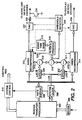
- FIGURE 2 is a block diagram of a audio/video decompression apparatus embodying the present invention.
- FIGURE 3 s a block diagram of apparatus for providing the receiver system clock signal having substantially the same rate as the system clock of the compression apparatus.
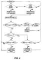
- FIGURE 4 is a flow chart of the operation of the FIGURE 2 apparatus.
- FIGURES 5 is a block diagram of alternative muting circuitry which may be implemented in the FIGURE 2 apparatus.
- FIGURE 1 illustrates a typical system in which the invention may be practiced, which system is a compressed digital video signal transmission arrangement.
- video signal from a source 10 is applied to a video signal compression element 11 which may include a motion compensated predictive encoder utilizing discrete cosine transforms.
- Compressed video signal from the element 11 is coupled to a formatter 12.
- the formatter arranges the compressed video signal and other ancillary data according to some signal protocol such as MPEG, a standard developed by the International Organization for Standardization (Organization Internationale De Normalisation).
- the standardized signal is applied to a transport processor 13, which divides the signal into packets of data and adds certain overhead to provide some noise immunity for the transmission purposes.
- the transport packets which normally occur at a non-uniform rate are applied to a rate buffer 14 which provides output data at a relatively constant rate conducive to efficient use of a relatively narrow bandwidth transmission channel.
- the buffered data is coupled to a modem 15 which performs the signal transmission.
- a system clock 22 provides clocking signal to operate much of the apparatus, at least including the transport processor. This clock will operate at a fixed frequency such as 27 MHz for example. As shown herein, however, it is used to generate timing information.
- the system clock is coupled to the clock input of a counter 23 which may be arranged to count modulo 230, for example.
- the count values output by the counter are applied to two latches 24 and 25.
- the latch 24 is conditioned by the video source to latch count values on the occurrence of respective frame intervals. These count values are denoted presentation time stamps, PTS's, and are included in the compressed video signal stream by the formatter 12, and are used by the receiver to provide lip-synchronization of associated audio and video information.
- the latch 25 is conditioned by the transport processor 13 (or the system controller 21) to latch count values according to a predetermined schedule. These count values are denoted system clock references, SCR's, and are embedded as auxiliary data within respective auxiliary transport packets.
- Audio signal associated with the video signal from source 10 is applied to an audio signal compressor 18.
- the compressor 18 provides frame sampling pulses (independent of video frames) to control a latch 19. Responsive to the sampling pulses, the latch 19 captures count values provided by the counter 23. These latched values correspond to audio presentation time stamps PTS aud .
- the PTS aud are incorporated in the compressed audio signal provided by the compressor 18.
- the compressed audio signal is coupled to a transport processor 17 which divides the signal into packets of data and adds certain overhead to provide some noise immunity for transmission purposes.
- the audio transport packets provided by the processor 17 are coupled to a multiplexor 16 which time division multiplexes the audio and video transport packets. In the figure, separate transport processors are shown in the audio and video signal processing channels. For systems wherein the data rate is moderate, the functions of the two transport processors and the multiplexor 16 may be subsumed in a single transport processor.
- the system controller 21 is a variable state machine programmed to coordinate the various processing elements. Note that the controller 21, the compressors 11 and 18, the transport processors 13 and 17, and the rate buffer 14 may or may not operate synchronously via a common clocking arrangement as long as proper handshaking is provided between processing elements. However, the two compressors both derive PTS values from the same reference counter 23, thus a precise timing relationship between the two compressed signals is provided in the compressed output signal.
- FIGURE 2 illustrates an exemplary receiver apparatus embodying the invention wherein the modem 200 performs the inverse function of the modem 15 and the rate buffer 206 performs, in effect, the inverse function of the rate buffer 14.
- An inverse transport processor 202 divides respective transport packets by service and allocates the respective packet payloads differing memory blocks in the rate buffer 206. In so doing the respective transport packet signal payloads are separated from the auxiliary data, with the auxiliary data applied to the system controller 210.
- a separate transport processor may be included in each processing channel and arranged to recognize and process only data associated with the respective channels.
- Compressed video data from the rate buffer 206 is passed to the video decompressor 214.
- the rate buffer 206 accepts compressed video data at a bursty or inconsistent rate, and provides data on demand to the decompressor 214.
- the decompressor responsive to the compressed video signal, generates non-compressed video signal for display or for storage etc., in appropriate display or storage devices (not shown).
- Compressed audio data from the inverse transport processor 202 is applied to the rate buffer 206, which provides compressed audio signal according to the system protocol to the audio decompressor 212.
- the decompressor, 212 responsive to the compressed audio signal generates non-compressed audio signal for reproduction or for storage etc., in appropriate speakers or storage devices (not shown).
- the inverse processor 202 also provides SCR's from the auxiliary transport data, and control signals to a system clock generator 208.
- the clock generator responsive to these signals generates a system clock signal synchronous with at least the transport processor operation. This system clock signal is applied to the receiver system controller 210 to control the timing of appropriate processing elements.
- FIG. 3 illustrates details of an exemplary clock regenerator 208.
- Data from the receiver modem 200 is coupled to the inverse transport processor 202', including an auxiliary packet detector 31.
- the inverse transport processor 202' separates transport header data from the respective transport packet payloads. Responsive to the transport header data, the processor 202' demultiplexes payloads of the desired associated audio and video program components and payloads of associated auxiliary data. The audio video and auxiliary payloads are written to separate memory blocks of the rate buffer 208.
- the respective memory blocks are each operated as first-in-first out memories or FIFO's, writing data when it is available from the modem and reading data when it is demanded by the corresponding component signal processor (not shown).
- SCR's present in particular auxiliary packets are routed and stored in a memory element, 34.
- An auxiliary packet detector 31 which may be a matched filter arranged to recognize the code words designating an auxiliary transport packet containing a SCR, produces a control pulse on the occurrence of transport packets containing such data.
- the control pulse is utilized to capture and store within a latch 35, the count value currently exhibited by the local counter 36 at a time precisely related to the time of detection.
- the local counter 36 is arranged to count pulses provided by a voltage controlled oscillator 37.
- the counter 36 is arranged to count modulo M which may be, but is not necessarily, the same number as its counterpart counter in the encoder (counter 23). If M differs from N the difference may be accommodated in the error equation.
- the voltage controlled oscillator 37 is controlled by a low pass filtered 38 error signal provided by a clock controller 39.
- the error signal is generated in the following fashion. Let the SCR arriving at time n be designated SCR n and the local count value concurrently captured in the latch 35 be designated LCR n .
- the clock controller reads the successive values of SCR's and LCR's and forms an error signal E proportional to the differences E ⁇
- the error signal E is utilized to condition the voltage controlled oscillator 37 to a frequency tending to equalize the differences. As indicated previously, negative differences exhibited due to modulo counter wrap around, may be ignored.
- the error signal produced by the clock controller 39 may be in the form of a pulse width modulated signal, which may be rendered into an analog error signal by implementing the low pass filter 38 in analog components.
- LTE Long term error
- the error signals E and LTE will vary in discrete steps. As such, once the system is "synchronized" the error signal will dither one unit about the null point.
- the preferred method of synchronization is to initiate control of the voltage controlled oscillator using the error signal E until a one unit dither occurs in the error signal E, and then to switch to the use of the long term error signal LTE to control the voltage controlled oscillator.
- the system clock signal provided by the VCXO 37 may be utilized to operate at least the transport processor and rate buffers. Since it is synchronized at least in frequency with the encoder system clock, the possibility of rate buffer overflow or underflow due to clock timing errors is substantially non-existent.
- a presentation time stamp PTS vid is included in the compressed video signal associated with predetermined video data.
- the PTS vid is indicative of the relative time that the associated video is to be displayed.
- the compressed audio signal includes presentation time stamps PTS aud associated with audio to be reproduced at times related to the respective PTS aud .
- the PTS aud and PTS vid may not be compared directly to provide A/V synchronization because the respective samples were determined at different instants.
- the respective PTS values are compared to a continuous time base which is the receiver clock provided by the VCXO 37. This is done by sampling local count values LCR generated by the system clock 208 to capture local time stamps.
- the LCR When data associated with an associated PTS is presented, The LCR is sampled. For example, The audio decompressor 212 issues a PTS aud when a respective audio frame is output for reproduction. At these times a control signal conditions the latch 220 to sample the LCR, the values of which will be designated LAS, for local audio stamp. Similarly when the video decompressor provides a video frame for display, it provides a PTS vid and a control pulse to condition a latch 222 to store the current value of the LCR. These LCR values are designated LVS for local video stamps.
- ERR PTS ⁇ V-PTS - ⁇ A-PTS
- Two mechanisms may be used to adjust the A/V synchronization based upon the error signal ERR PTS ; skips and repeats of data sections and conversion clock deviation. Skipping fixed intervals or "frames" of audio advances the audio data stream by a fixed interval relative to the video signal. Repeating (or muting without consuming data) delays the audio data stream by fixed intervals relative to the video signal. Skipping and repeating audio frames is audible under many conditions, and therefore is only utilized for coarse adjustment of synchronization. Even so, brief skipping or repeating may be preferable to discernible audio/video synchronization errors.
- the error signal ERR PTS is applied to a filter and processing element 216.
- a filter function therein smoothes the signal ERR PTS to minimize aberrant effects that might otherwise be generated by signal noise.
- the processing function in the element 216 then examines the smoothed error signal and determines whether a skip/repeat of audio should be utilized to effect coarse synchronization of the audio and video signals and/or whether an adjustment to the audio processing frequency should be utilized to effect fine synchronization. If a coarse synchronization adjustment is determined to be necessary, the processor 216 provides a control signal (S/R) to the audio decompressor 212 to condition the decompressor to skip or repeat the current decompressed audio frame. Alternatively, or in addition to the coarse adjustment, if a fine adjustment is determined to be necessary, the processor 216 provides a control signal to the audio time base 215 to adjust the frequency of the audio processing clock signal.
- S/R control signal
- the processing algorithm is detailed in the flow chart of FIGURE 4.
- the system monitors 401 the audio decompressor for the occurrence of a PTS aud and if a PTS aud is detected it is read 403 and a local clock reference LAS is captured and stored. If a PTS aud has not occurred, the system monitors the video compressor for a PTS vid 402. If a PTS vid has occurred, the PTS vid is read and a local clock reference LVS is captured and stored.
- ERR PTS ⁇ V-PTS - ⁇ A-PTS.
- the magnitude of the error signal is examined 406 to determine if it is greater than one half an audio frame interval. If it is greater than one half an audio frame interval, the error signal is checked for polarity 407. If the polarity is positive, the current audio frame is repeated 409. If it is negative the current audio frame is skipped 408. After skipping or repeating a frame the system iterates back to the start position to wait for the next occurrence of PTS's.
- the error is examined to determine if it is greater than zero 410. If the error is greater than zero, the error is checked 412 to determine if it is less than the previous error signal. If it is less than the previous error signal, this is an indication that the system is converging toward synchronization, and the synchronization control parameters are not changed. The system returns to the start position to wait for the next PTS's. Conversely, if the error has increased over the previous error signal, the audio system processing clock is adjusted to lessen its frequency 414.
- step 410 if the error is less than zero (negative), it is checked 411 to determine whether it is greater than the previous error signal. If it is greater than the previous error signal, this is also an indication that the system is converging toward synchronization, and the synchronization control parameters are not changed. Alternatively if the current error signal is less than the previous error signal the system is moving further out of synchronization and the audio processing clock frequency is increased 413. After processing steps 412 and 413 the system returns to wait for the next occurrence of PTS's. It will be noted in this example, that the system performs only coarse adjustments via skipping or repeating audio frames until the A/V synchronization error is reduced to less than one half an audio frame interval.
- the filtered error signal is compared against a predetermined threshold related to the size of respective audio frames. If the error signal is less than the threshold, indicative that the audio-video timing error is less than an audio frame, the error signal is coupled to the audio time base circuit 215, wherein it is utilized to adjust the frequency of the audio signal processing (decompression) clock. Alternatively, if the error signal is greater than the threshold, the error signal may be divided by the audio frame interval to determine the number of audio frames that the audio and video signal are misaligned. The integer portion of the quotient is applied to the audio decompressor to condition the audio decompressor to skip or repeat that number of audio frames. The polarity of the error signal will determine whether audio frames should be skipped or repeated. Nominally the compressed data is arranged in a buffer memory prior to being decoded, hence skipping or repeating audio frames is a simple matter of controllably enabling the memory read/write commands.
- the fractional portion of the quotient is coupled to the audio time base circuit 215, where it is utilized to adjust the audio processing clock to fine tune the A/V synchronization.
- the rate of production of audio PTS's is proportional to the processing speed of the audio decompressor.
- the processing speed of the audio decompressor is directly proportional to the frequency of the clock signal used to operate the audio decompressor. If the clock frequency of the audio decompressor is independent of the clock used to operate the video decompressor, and is finely adjustable, then the relative rate of occurrence of the audio and video PTS's can be adjusted and the A/V finely synchronized.
- Decompressed audio signal is coupled to a digital-to-analog converter (DAC) 227.
- Analog output signal from the DAC 227 is coupled to further analog processing circuitry (not shown) via a resistor 228.
- the conduction path of a muting transistor 229 is coupled between the resistor 228 and ground potential.
- the control electrode of the transistor is coupled to an output connection of a threshold detector 225. A positive control voltage of greater than one V be will condition the transistor 229 to clamp the audio output signal from DAC 227 to ground potential, thereby muting the audio signal.
- a compressed audio signal will include a plurality of components such as a left signal, a right signal, etc.
- FIGURE 2 shows only one audio output for simplicity, however each audio channel will include a muting-circuit controlled by a common muting control signal.
- Muting the audio signal may be performed for various reasons, not the least of which is loss of lip-sync.
- the current apparatus is unique in that it mutes audio based on lip-sync error.
- a human viewer can notice lip-sync errors of -20 ms or +40 ms.
- audio is muted if the lip-sync error exceeds approximately 13 ms.
- the 13 ms threshold was chosen to be less than 20 ms but greater than one-half an MPEG1, layer II audio frame (which is 24 ms).
- the threshold was selected to be slightly greater than one half the audio frame because with A/V synchronizing frame skips and repeats, an initial synchronizing state at a half frame (12 ms) is possible, and a threshold of approximately 12 ms or less could result in synchronized, but muted audio.
- a threshold equivalent to one half frame produces intermittent muting due to minor fluctuation in calculated lip-sync errors due to clock and PTS strobe sampling uncertainties.
- the muting control signal is generated by the threshold detector 225, which monitors the A/V synchronization error signal available from the subtracter 219. When the error signal exceeds a value corresponding to 13 ms, a muting control value is generated. To preclude noise or other impulsive conditions from causing generation of false muting signals, the error signals from the subtracter 219 may be low pass filtered before application to the threshold detector 225.
- Dashed arrows emanating from the detector 225 and terminating on the DAC 227 and the audio decompressor 212 indicate alternative muting possibilities.
- the muting control signal may be designed for disabling the output of the DAC 227 or the output of the decompressor 212. In either instance the disabling function should be arranged to condition the respective processing element to output a signal amplitude value midway between the output signal dynamic range.
- the FIGURE 2 arrangement also indicates that video muting (or blanking) may be implemented via control of the video DAC 224.
- FIGURE 5 illustrates an alternative muting arrangement.
- the skip/repeat (S/R) signal generated by the filter 216 is used as the primary muting control.
- This signal is coupled to the muting circuitry via an OR gate 230.
- a threshold detector, 231 may be included to monitor the audio time base fine control signal and generate a secondary muting control signal.
- This secondary control signal is also coupled to the muting circuitry via the OR gate 230.
- the apparatus of FIGURE 5 illustrates a further possible muting circuit, consisting of an AND gate, 226, to selectively couple the decompressed audio signal from the decompressor 212 to the DAC 227.
- Nominally audio signals are bipolar (AC) and swing about zero value.
- the AND gate when in the decoupled state, desirably outputs zero value which is the middle of the signal dynamic range.
- a further threshold detector, 232 may be included to monitor the error signal generated by the clock controller 39 shown in FIGURE 3.
- the threshold detector, 232 generates a muting control signal when the error signal produced by the controller represents a frequency deviation from the locked condition by, for example, 0.2.
- This muting control signal is coupled to the OR gate 230 to effect audio muting until the system clock is substantially synchronized with the corresponding encoding system clock.
- detection apparatus may be coupled to measure the frequency deviation of the audio time base 215 for generating a further muting signal which may be ORed in the gate 230.
Landscapes
- Engineering & Computer Science (AREA)
- Multimedia (AREA)
- Signal Processing (AREA)
- Television Signal Processing For Recording (AREA)
- Compression Or Coding Systems Of Tv Signals (AREA)
- Two-Way Televisions, Distribution Of Moving Picture Or The Like (AREA)
- Synchronisation In Digital Transmission Systems (AREA)
- Signal Processing For Digital Recording And Reproducing (AREA)
Applications Claiming Priority (2)
| Application Number | Priority Date | Filing Date | Title |
|---|---|---|---|
| US08/245,113 US5467139A (en) | 1993-09-30 | 1994-05-17 | Muting apparatus for a compressed audio/video signal receiver |
| US245113 | 1994-05-17 |
Publications (3)
| Publication Number | Publication Date |
|---|---|
| EP0683604A2 true EP0683604A2 (de) | 1995-11-22 |
| EP0683604A3 EP0683604A3 (de) | 1998-10-28 |
| EP0683604B1 EP0683604B1 (de) | 2002-07-31 |
Family
ID=22925345
Family Applications (1)
| Application Number | Title | Priority Date | Filing Date |
|---|---|---|---|
| EP95107007A Expired - Lifetime EP0683604B1 (de) | 1994-05-17 | 1995-05-09 | Abschaltvorrichtung für Empfänger eines komprimierten Video-/Audiosignals |
Country Status (12)
| Country | Link |
|---|---|
| US (1) | US5467139A (de) |
| EP (1) | EP0683604B1 (de) |
| JP (1) | JP3932059B2 (de) |
| KR (1) | KR100366401B1 (de) |
| CN (1) | CN1088305C (de) |
| BR (1) | BR9502039A (de) |
| CA (1) | CA2147013C (de) |
| DE (1) | DE69527573T2 (de) |
| MY (1) | MY112618A (de) |
| PL (1) | PL177313B1 (de) |
| RU (1) | RU2150792C1 (de) |
| TW (1) | TW325632B (de) |
Cited By (7)
| Publication number | Priority date | Publication date | Assignee | Title |
|---|---|---|---|---|
| NL1012767C2 (nl) * | 1998-08-03 | 2000-02-04 | Japan Adv Inst Science & Tech | Werkwijze voor het verwerken van een audiosignaal in een samengesteld audio-video signaal. |
| EP1071290A3 (de) * | 1999-07-21 | 2003-05-28 | Thomson Licensing S.A. | Synchronisierungsgerät für Empfänger von komprimiertem Ton und Video |
| US6757432B2 (en) | 1998-07-17 | 2004-06-29 | Matsushita Electric Industrial Co., Ltd. | Apparatus for transmitting and/or receiving stream data and method for producing the same |
| EP1766962A4 (de) * | 2004-06-22 | 2009-03-25 | Sarnoff Corp | Verfahren und vorrichtung zur messung und/oder korrektur der audiovisuellen synchronisation |
| EP1367829A3 (de) * | 2002-05-31 | 2009-07-01 | Kabushiki Kaisha Toshiba | Audiowiedergabegerät und Audiowiedergabesteuerungsverfahren |
| US7561601B2 (en) * | 2000-10-23 | 2009-07-14 | Telediffusion De France | Method for synchronizing digital signals |
| EP1615433A4 (de) * | 2003-03-19 | 2010-05-26 | Panasonic Corp | Datenverarbeitungseinrichtung |
Families Citing this family (76)
| Publication number | Priority date | Publication date | Assignee | Title |
|---|---|---|---|---|
| US5486864A (en) * | 1993-05-13 | 1996-01-23 | Rca Thomson Licensing Corporation | Differential time code method and apparatus as for a compressed video signal |
| JPH07202820A (ja) * | 1993-12-28 | 1995-08-04 | Matsushita Electric Ind Co Ltd | ビットレート制御システム |
| JP3408617B2 (ja) * | 1994-03-16 | 2003-05-19 | 富士通株式会社 | 画像符号化データの同期ワード多重化方式 |
| US5603016A (en) * | 1994-08-03 | 1997-02-11 | Intel Corporation | Method for synchronizing playback of an audio track to a video track |
| US5594660A (en) * | 1994-09-30 | 1997-01-14 | Cirrus Logic, Inc. | Programmable audio-video synchronization method and apparatus for multimedia systems |
| US5598352A (en) * | 1994-09-30 | 1997-01-28 | Cirrus Logic, Inc. | Method and apparatus for audio and video synchronizing in MPEG playback systems |
| US5920842A (en) * | 1994-10-12 | 1999-07-06 | Pixel Instruments | Signal synchronization |
| JP3575100B2 (ja) * | 1994-11-14 | 2004-10-06 | ソニー株式会社 | データ送信/受信装置及び方法並びにデータ記録/再生装置及び方法 |
| JP3149328B2 (ja) * | 1995-01-09 | 2001-03-26 | 松下電器産業株式会社 | 送信装置と受信装置 |
| US5920572A (en) * | 1995-06-30 | 1999-07-06 | Divicom Inc. | Transport stream decoder/demultiplexer for hierarchically organized audio-video streams |
| US7512698B1 (en) * | 1995-07-14 | 2009-03-31 | Broadband Royalty Corporation | Dynamic quality adjustment based on changing streaming constraints |
| US9832244B2 (en) | 1995-07-14 | 2017-11-28 | Arris Enterprises Llc | Dynamic quality adjustment based on changing streaming constraints |
| US5570372A (en) * | 1995-11-08 | 1996-10-29 | Siemens Rolm Communications Inc. | Multimedia communications with system-dependent adaptive delays |
| US5784572A (en) * | 1995-12-29 | 1998-07-21 | Lsi Logic Corporation | Method and apparatus for compressing video and voice signals according to different standards |
| US5835493A (en) * | 1996-01-02 | 1998-11-10 | Divicom, Inc. | MPEG transport stream remultiplexer |
| JPH09200569A (ja) * | 1996-01-17 | 1997-07-31 | Sony Corp | フレームシンクロナイザー |
| US5918205A (en) * | 1996-01-30 | 1999-06-29 | Lsi Logic Corporation | Audio decoder employing error concealment technique |
| US5920833A (en) * | 1996-01-30 | 1999-07-06 | Lsi Logic Corporation | Audio decoder employing method and apparatus for soft-muting a compressed audio signal |
| JP3052824B2 (ja) * | 1996-02-19 | 2000-06-19 | 日本電気株式会社 | オーディオ再生時刻調整回路 |
| US5828414A (en) * | 1996-02-23 | 1998-10-27 | Divicom, Inc. | Reduction of timing jitter in audio-video transport streams |
| US5917482A (en) * | 1996-03-18 | 1999-06-29 | Philips Electronics N.A. Corporation | Data synchronizing system for multiple memory array processing field organized data |
| WO1997041683A1 (en) * | 1996-04-29 | 1997-11-06 | Princeton Video Image, Inc. | Audio enhanced electronic insertion of indicia into video |
| KR100274434B1 (ko) | 1996-07-05 | 2000-12-15 | 모리시타 요이찌 | 디스플레이 시간 스탬핑과 다중 비디오 오브젝트평면의 동기화방법 |
| US6002441A (en) * | 1996-10-28 | 1999-12-14 | National Semiconductor Corporation | Audio/video subprocessor method and structure |
| US5864820A (en) * | 1996-12-20 | 1999-01-26 | U S West, Inc. | Method, system and product for mixing of encoded audio signals |
| US5845251A (en) * | 1996-12-20 | 1998-12-01 | U S West, Inc. | Method, system and product for modifying the bandwidth of subband encoded audio data |
| US6477496B1 (en) | 1996-12-20 | 2002-11-05 | Eliot M. Case | Signal synthesis by decoding subband scale factors from one audio signal and subband samples from different one |
| US6782365B1 (en) | 1996-12-20 | 2004-08-24 | Qwest Communications International Inc. | Graphic interface system and product for editing encoded audio data |
| US6463405B1 (en) | 1996-12-20 | 2002-10-08 | Eliot M. Case | Audiophile encoding of digital audio data using 2-bit polarity/magnitude indicator and 8-bit scale factor for each subband |
| US5864813A (en) * | 1996-12-20 | 1999-01-26 | U S West, Inc. | Method, system and product for harmonic enhancement of encoded audio signals |
| US6516299B1 (en) | 1996-12-20 | 2003-02-04 | Qwest Communication International, Inc. | Method, system and product for modifying the dynamic range of encoded audio signals |
| JP3000949B2 (ja) * | 1997-02-12 | 2000-01-17 | 日本電気株式会社 | 音声・画像同期圧縮再生装置及びその方法 |
| US6236681B1 (en) | 1997-07-31 | 2001-05-22 | Lsi Logic Corporation | Method for decoding MPEG compliant video bitstreams meeting 2-frame and letterboxing requirements |
| US6289053B1 (en) | 1997-07-31 | 2001-09-11 | Lsi Logic Corporation | Architecture for decoding MPEG compliant video bitstreams meeting 2-frame and letterboxing requirements |
| US6122316A (en) * | 1997-07-31 | 2000-09-19 | Lsi Logic Corporation | MPEG decoding system meeting 2-frame store and letterboxing requirements |
| US6266091B1 (en) | 1997-07-31 | 2001-07-24 | Lsi Logic Corporation | System and method for low delay mode operation video decoding |
| US6310918B1 (en) | 1997-07-31 | 2001-10-30 | Lsi Logic Corporation | System and method for motion vector extraction and computation meeting 2-frame store and letterboxing requirements |
| US6101221A (en) * | 1997-07-31 | 2000-08-08 | Lsi Logic Corporation | Video bitstream symbol extractor for use in decoding MPEG compliant video bitstreams meeting 2-frame and letterboxing requirements |
| US7366670B1 (en) * | 1997-08-05 | 2008-04-29 | At&T Corp. | Method and system for aligning natural and synthetic video to speech synthesis |
| KR19990040286A (ko) * | 1997-11-17 | 1999-06-05 | 윤종용 | 스크린 뮤트기능을 갖는 영상 재생장치 및 그에 따른 스크린 뮤트방법 |
| JP3063841B2 (ja) * | 1997-11-26 | 2000-07-12 | 日本電気株式会社 | オーディオ・ビデオ同期再生装置 |
| US6292490B1 (en) | 1998-01-14 | 2001-09-18 | Skystream Corporation | Receipts and dispatch timing of transport packets in a video program bearing stream remultiplexer |
| US6351471B1 (en) | 1998-01-14 | 2002-02-26 | Skystream Networks Inc. | Brandwidth optimization of video program bearing transport streams |
| US6351474B1 (en) * | 1998-01-14 | 2002-02-26 | Skystream Networks Inc. | Network distributed remultiplexer for video program bearing transport streams |
| US6195368B1 (en) | 1998-01-14 | 2001-02-27 | Skystream Corporation | Re-timing of video program bearing streams transmitted by an asynchronous communication link |
| US6246701B1 (en) | 1998-01-14 | 2001-06-12 | Skystream Corporation | Reference time clock locking in a remultiplexer for video program bearing transport streams |
| DE19930824C2 (de) * | 1999-07-03 | 2001-05-31 | Grundig Ag | Bild- und Tonwiedergabegerät und Verfahren für dessen Betrieb |
| US6583821B1 (en) | 1999-07-16 | 2003-06-24 | Thomson Licensing S.A. | Synchronizing apparatus for a compressed audio/video signal receiver |
| DE19956913C2 (de) * | 1999-11-26 | 2001-11-29 | Grundig Ag | Verfahren und Vorrichtung zur Anpassung der Laufzeitdifferenz von Video- und Audiosignal in einem Fernsehgerät |
| JP2001231035A (ja) * | 2000-02-14 | 2001-08-24 | Nec Corp | 復号同期制御装置、復号装置、及び復号同期制御方法 |
| EP1139665A1 (de) * | 2000-03-29 | 2001-10-04 | Deutsche Thomson-Brandt Gmbh | Verfahren und Gerät für die Ausgabeverzögerungsänderung während der Video- oder Tonkodierung |
| JP4481444B2 (ja) * | 2000-06-30 | 2010-06-16 | 株式会社東芝 | 画像符号化装置 |
| US7039116B1 (en) * | 2000-11-07 | 2006-05-02 | Cisco Technology, Inc. | Methods and apparatus for embedding and format conversion of compressed video data |
| US7030930B2 (en) * | 2001-03-06 | 2006-04-18 | Ati Technologies, Inc. | System for digitized audio stream synchronization and method thereof |
| US8880709B2 (en) | 2001-09-12 | 2014-11-04 | Ericsson Television Inc. | Method and system for scheduled streaming of best effort data |
| CN1278549C (zh) | 2001-10-18 | 2006-10-04 | 松下电器产业株式会社 | 声像再现装置和声像再现方法 |
| CN1801949A (zh) | 2001-10-29 | 2006-07-12 | 松下电器产业株式会社 | 图像声音同步装置 |
| US6956871B2 (en) * | 2002-04-19 | 2005-10-18 | Thomson Licensing | Apparatus and method for synchronization of audio and video streams |
| US7283566B2 (en) * | 2002-06-14 | 2007-10-16 | Silicon Image, Inc. | Method and circuit for generating time stamp data from an embedded-clock audio data stream and a video clock |
| CN1720749B (zh) | 2002-12-04 | 2010-12-08 | 三叉微系统(远东)有限公司 | 自动测试音频/视频同步的方法 |
| US20040117840A1 (en) * | 2002-12-12 | 2004-06-17 | Boudreau Paul A. | Data enhanced multi-media system for a set-top terminal |
| EP1635562B1 (de) * | 2003-05-28 | 2019-03-13 | Panasonic Corporation | Empfängervorrichtung mit digitaler schnittstelle |
| US7693222B2 (en) * | 2003-08-13 | 2010-04-06 | Ericsson Television Inc. | Method and system for re-multiplexing of content-modified MPEG-2 transport streams using PCR interpolation |
| US7471337B2 (en) * | 2004-06-09 | 2008-12-30 | Lsi Corporation | Method of audio-video synchronization |
| US7400653B2 (en) * | 2004-06-18 | 2008-07-15 | Dolby Laboratories Licensing Corporation | Maintaining synchronization of streaming audio and video using internet protocol |
| US20060209210A1 (en) * | 2005-03-18 | 2006-09-21 | Ati Technologies Inc. | Automatic audio and video synchronization |
| KR100638138B1 (ko) * | 2005-05-24 | 2006-10-24 | 주식회사 픽스트리 | 비디오/오디오 부호화 및 다중화 기능을 가진 하드웨어장치 및 그 작동 방법 |
| CN101208949A (zh) * | 2005-06-29 | 2008-06-25 | 天龙马兰士集团有限公司 | 再生装置 |
| US8670537B2 (en) * | 2006-07-31 | 2014-03-11 | Cisco Technology, Inc. | Adjusting audio volume in a conference call environment |
| JPWO2011074383A1 (ja) | 2009-12-14 | 2013-04-25 | 新日鐵住金株式会社 | 誘導加熱装置の制御装置、誘導加熱システム及び誘導加熱装置の制御方法 |
| US8640181B1 (en) * | 2010-09-15 | 2014-01-28 | Mlb Advanced Media, L.P. | Synchronous and multi-sourced audio and video broadcast |
| TWI513320B (zh) * | 2012-06-25 | 2015-12-11 | Hon Hai Prec Ind Co Ltd | 視訊會議裝置及其唇形同步的方法 |
| CN104935827B (zh) * | 2014-03-21 | 2018-07-06 | 北京同步科技有限公司 | 视频帧同步时嵌入音频的处理系统及处理方法 |
| US10178281B2 (en) | 2014-07-28 | 2019-01-08 | Starkey Laboratories, Inc. | System and method for synchronizing audio and video signals for a listening system |
| US11228799B2 (en) * | 2019-04-17 | 2022-01-18 | Comcast Cable Communications, Llc | Methods and systems for content synchronization |
| US12542949B1 (en) * | 2024-07-30 | 2026-02-03 | Avago Technologies International Sales Pte. Limited | Systems and methods for latency optimization for cloud applications |
Family Cites Families (14)
| Publication number | Priority date | Publication date | Assignee | Title |
|---|---|---|---|---|
| US4313135B1 (en) * | 1980-07-28 | 1996-01-02 | J Carl Cooper | Method and apparatus for preserving or restoring audio to video |
| US4398220A (en) * | 1980-09-05 | 1983-08-09 | Tokyo Shibaura Denki Kabushiki Kaisha | Circuit for detecting the operational state of a television receiver |
| US5202761A (en) * | 1984-11-26 | 1993-04-13 | Cooper J Carl | Audio synchronization apparatus |
| USRE33535E (en) * | 1985-09-16 | 1991-02-12 | Audio to video timing equalizer method and apparatus | |
| US4703355A (en) * | 1985-09-16 | 1987-10-27 | Cooper J Carl | Audio to video timing equalizer method and apparatus |
| JPH06103859B2 (ja) * | 1988-10-24 | 1994-12-14 | 松下電器産業株式会社 | 音声信号復調回路 |
| JP2944131B2 (ja) * | 1990-03-22 | 1999-08-30 | 株式会社東芝 | ビデオ記録再生装置 |
| GB2244184B (en) * | 1990-05-16 | 1993-11-17 | Thames Television | Audio delay detector |
| JP2808884B2 (ja) * | 1990-10-31 | 1998-10-08 | 松下電器産業株式会社 | テレビジョン信号変換装置 |
| RU2012158C1 (ru) * | 1991-01-08 | 1994-04-30 | Поволжский институт информатики, радиотехники и связи | Приемник телевизионного сигнала |
| JPH0817485B2 (ja) * | 1991-01-29 | 1996-02-21 | 三洋電機株式会社 | Muse音声デコーダ |
| JPH05191784A (ja) * | 1992-01-13 | 1993-07-30 | Pioneer Electron Corp | Muse音声デコーダおよびmuse伝送システム |
| US5287182A (en) * | 1992-07-02 | 1994-02-15 | At&T Bell Laboratories | Timing recovery for variable bit-rate video on asynchronous transfer mode (ATM) networks |
| KR0155730B1 (ko) * | 1993-03-31 | 1998-11-16 | 김광호 | 뮤트회로 및 방법 |
-
1994
- 1994-05-17 US US08/245,113 patent/US5467139A/en not_active Expired - Lifetime
-
1995
- 1995-04-07 TW TW084103313A patent/TW325632B/zh not_active IP Right Cessation
- 1995-04-13 CA CA002147013A patent/CA2147013C/en not_active Expired - Fee Related
- 1995-04-27 MY MYPI95001099A patent/MY112618A/en unknown
- 1995-05-09 EP EP95107007A patent/EP0683604B1/de not_active Expired - Lifetime
- 1995-05-09 DE DE69527573T patent/DE69527573T2/de not_active Expired - Lifetime
- 1995-05-12 JP JP14798595A patent/JP3932059B2/ja not_active Expired - Fee Related
- 1995-05-13 KR KR1019950011793A patent/KR100366401B1/ko not_active Expired - Fee Related
- 1995-05-15 BR BR9502039A patent/BR9502039A/pt not_active IP Right Cessation
- 1995-05-16 CN CN95104856A patent/CN1088305C/zh not_active Expired - Lifetime
- 1995-05-16 PL PL95308615A patent/PL177313B1/pl not_active IP Right Cessation
- 1995-05-16 RU RU95107648/09A patent/RU2150792C1/ru not_active IP Right Cessation
Cited By (9)
| Publication number | Priority date | Publication date | Assignee | Title |
|---|---|---|---|---|
| US6757432B2 (en) | 1998-07-17 | 2004-06-29 | Matsushita Electric Industrial Co., Ltd. | Apparatus for transmitting and/or receiving stream data and method for producing the same |
| NL1012767C2 (nl) * | 1998-08-03 | 2000-02-04 | Japan Adv Inst Science & Tech | Werkwijze voor het verwerken van een audiosignaal in een samengesteld audio-video signaal. |
| EP1071290A3 (de) * | 1999-07-21 | 2003-05-28 | Thomson Licensing S.A. | Synchronisierungsgerät für Empfänger von komprimiertem Ton und Video |
| KR100805757B1 (ko) * | 1999-07-21 | 2008-02-21 | 톰슨 라이센싱 | 압축 오디오/비디오 신호 수신기용 동기화 장치 및 방법 |
| US7561601B2 (en) * | 2000-10-23 | 2009-07-14 | Telediffusion De France | Method for synchronizing digital signals |
| EP1367829A3 (de) * | 2002-05-31 | 2009-07-01 | Kabushiki Kaisha Toshiba | Audiowiedergabegerät und Audiowiedergabesteuerungsverfahren |
| EP1615433A4 (de) * | 2003-03-19 | 2010-05-26 | Panasonic Corp | Datenverarbeitungseinrichtung |
| EP1766962A4 (de) * | 2004-06-22 | 2009-03-25 | Sarnoff Corp | Verfahren und vorrichtung zur messung und/oder korrektur der audiovisuellen synchronisation |
| US7593061B2 (en) | 2004-06-22 | 2009-09-22 | Sarnoff Corporation | Method and apparatus for measuring and/or correcting audio/visual synchronization |
Also Published As
| Publication number | Publication date |
|---|---|
| KR100366401B1 (ko) | 2003-02-26 |
| PL308615A1 (en) | 1995-11-27 |
| CA2147013A1 (en) | 1995-11-18 |
| JPH0846884A (ja) | 1996-02-16 |
| DE69527573D1 (de) | 2002-09-05 |
| RU95107648A (ru) | 1997-02-10 |
| KR950035369A (ko) | 1995-12-30 |
| CA2147013C (en) | 2004-12-07 |
| RU2150792C1 (ru) | 2000-06-10 |
| CN1116390A (zh) | 1996-02-07 |
| JP3932059B2 (ja) | 2007-06-20 |
| PL177313B1 (pl) | 1999-10-29 |
| MY112618A (en) | 2001-07-31 |
| EP0683604A3 (de) | 1998-10-28 |
| US5467139A (en) | 1995-11-14 |
| CN1088305C (zh) | 2002-07-24 |
| EP0683604B1 (de) | 2002-07-31 |
| BR9502039A (pt) | 1996-01-16 |
| TW325632B (en) | 1998-01-21 |
| DE69527573T2 (de) | 2003-01-09 |
Similar Documents
| Publication | Publication Date | Title |
|---|---|---|
| US5467139A (en) | Muting apparatus for a compressed audio/video signal receiver | |
| US6583821B1 (en) | Synchronizing apparatus for a compressed audio/video signal receiver | |
| EP0648056B1 (de) | Ton-/Videosynchronisierung in einem digitalen Übertragungssystem | |
| CN100515091C (zh) | 用于对压缩的视频信号接收系统进行同步的方法 | |
| US5381181A (en) | Clock recovery apparatus as for a compressed video signal | |
| EP0731615B1 (de) | Bilddekodierungssystem zur Dekodierung von Bilddaten in Synchronisation mit einem Systemtakt | |
| KR20070105947A (ko) | 압축 오디오/비디오 신호 수신기용 동기화 장치 및 방법 | |
| KR100224099B1 (ko) | 오디오/비디오 신호의 동기장치 및 방법 | |
| JPS6114705B2 (de) | ||
| HK1034348B (en) | Synchronizing apparatus and method for a compressed audio/video signal receiver | |
| JPH08280008A (ja) | 符号化方法及び装置 |
Legal Events
| Date | Code | Title | Description |
|---|---|---|---|
| PUAI | Public reference made under article 153(3) epc to a published international application that has entered the european phase |
Free format text: ORIGINAL CODE: 0009012 |
|
| AK | Designated contracting states |
Kind code of ref document: A2 Designated state(s): DE FR GB IT |
|
| PUAL | Search report despatched |
Free format text: ORIGINAL CODE: 0009013 |
|
| AK | Designated contracting states |
Kind code of ref document: A3 Designated state(s): DE FR GB IT |
|
| RHK1 | Main classification (correction) |
Ipc: H04N 7/52 |
|
| 17P | Request for examination filed |
Effective date: 19990406 |
|
| 17Q | First examination report despatched |
Effective date: 19991216 |
|
| GRAG | Despatch of communication of intention to grant |
Free format text: ORIGINAL CODE: EPIDOS AGRA |
|
| GRAG | Despatch of communication of intention to grant |
Free format text: ORIGINAL CODE: EPIDOS AGRA |
|
| GRAH | Despatch of communication of intention to grant a patent |
Free format text: ORIGINAL CODE: EPIDOS IGRA |
|
| GRAH | Despatch of communication of intention to grant a patent |
Free format text: ORIGINAL CODE: EPIDOS IGRA |
|
| GRAA | (expected) grant |
Free format text: ORIGINAL CODE: 0009210 |
|
| AK | Designated contracting states |
Kind code of ref document: B1 Designated state(s): DE FR GB IT |
|
| REG | Reference to a national code |
Ref country code: GB Ref legal event code: FG4D |
|
| REF | Corresponds to: |
Ref document number: 69527573 Country of ref document: DE Date of ref document: 20020905 |
|
| ET | Fr: translation filed | ||
| REG | Reference to a national code |
Ref country code: GB Ref legal event code: 746 Effective date: 20030103 |
|
| PLBE | No opposition filed within time limit |
Free format text: ORIGINAL CODE: 0009261 |
|
| STAA | Information on the status of an ep patent application or granted ep patent |
Free format text: STATUS: NO OPPOSITION FILED WITHIN TIME LIMIT |
|
| 26N | No opposition filed |
Effective date: 20030506 |
|
| REG | Reference to a national code |
Ref country code: DE Ref legal event code: R082 Ref document number: 69527573 Country of ref document: DE Representative=s name: MANFRED ROSSMANITH, DE |
|
| REG | Reference to a national code |
Ref country code: DE Ref legal event code: R082 Ref document number: 69527573 Country of ref document: DE Representative=s name: ROSSMANITH, MANFRED, DIPL.-PHYS. DR.RER.NAT., DE Effective date: 20120724 Ref country code: DE Ref legal event code: R081 Ref document number: 69527573 Country of ref document: DE Owner name: THOMSON LICENSING, FR Free format text: FORMER OWNER: THOMSON CONSUMER ELECTRONICS, INC., INDIANAPOLIS, IND., US Effective date: 20120724 Ref country code: DE Ref legal event code: R081 Ref document number: 69527573 Country of ref document: DE Owner name: THOMSON LICENSING, FR Free format text: FORMER OWNER: THOMSON CONSUMER ELECTRONICS, INC., INDIANAPOLIS, US Effective date: 20120724 |
|
| PGFP | Annual fee paid to national office [announced via postgrant information from national office to epo] |
Ref country code: GB Payment date: 20140527 Year of fee payment: 20 |
|
| PGFP | Annual fee paid to national office [announced via postgrant information from national office to epo] |
Ref country code: IT Payment date: 20140523 Year of fee payment: 20 Ref country code: DE Payment date: 20140523 Year of fee payment: 20 |
|
| PGFP | Annual fee paid to national office [announced via postgrant information from national office to epo] |
Ref country code: FR Payment date: 20140516 Year of fee payment: 20 |
|
| REG | Reference to a national code |
Ref country code: DE Ref legal event code: R071 Ref document number: 69527573 Country of ref document: DE |
|
| REG | Reference to a national code |
Ref country code: GB Ref legal event code: PE20 Expiry date: 20150508 |
|
| PG25 | Lapsed in a contracting state [announced via postgrant information from national office to epo] |
Ref country code: GB Free format text: LAPSE BECAUSE OF EXPIRATION OF PROTECTION Effective date: 20150508 |