EP0683860B1 - Dispositif de guidage d'air - Google Patents
Dispositif de guidage d'air Download PDFInfo
- Publication number
- EP0683860B1 EP0683860B1 EP94905809A EP94905809A EP0683860B1 EP 0683860 B1 EP0683860 B1 EP 0683860B1 EP 94905809 A EP94905809 A EP 94905809A EP 94905809 A EP94905809 A EP 94905809A EP 0683860 B1 EP0683860 B1 EP 0683860B1
- Authority
- EP
- European Patent Office
- Prior art keywords
- air flow
- air
- vanes
- guiding device
- vortical
- Prior art date
- Legal status (The legal status is an assumption and is not a legal conclusion. Google has not performed a legal analysis and makes no representation as to the accuracy of the status listed.)
- Expired - Lifetime
Links
- 239000000446 fuel Substances 0.000 description 8
- 238000002485 combustion reaction Methods 0.000 description 7
- 239000000203 mixture Substances 0.000 description 4
- 238000000034 method Methods 0.000 description 2
- 238000005266 casting Methods 0.000 description 1
- 239000008240 homogeneous mixture Substances 0.000 description 1
- 230000006698 induction Effects 0.000 description 1
- 239000002184 metal Substances 0.000 description 1
- 238000000465 moulding Methods 0.000 description 1
Images


Classifications
-
- F—MECHANICAL ENGINEERING; LIGHTING; HEATING; WEAPONS; BLASTING
- F02—COMBUSTION ENGINES; HOT-GAS OR COMBUSTION-PRODUCT ENGINE PLANTS
- F02M—SUPPLYING COMBUSTION ENGINES IN GENERAL WITH COMBUSTIBLE MIXTURES OR CONSTITUENTS THEREOF
- F02M29/00—Apparatus for re-atomising condensed fuel or homogenising fuel-air mixture
- F02M29/04—Apparatus for re-atomising condensed fuel or homogenising fuel-air mixture having screens, gratings, baffles or the like
-
- F—MECHANICAL ENGINEERING; LIGHTING; HEATING; WEAPONS; BLASTING
- F02—COMBUSTION ENGINES; HOT-GAS OR COMBUSTION-PRODUCT ENGINE PLANTS
- F02M—SUPPLYING COMBUSTION ENGINES IN GENERAL WITH COMBUSTIBLE MIXTURES OR CONSTITUENTS THEREOF
- F02M29/00—Apparatus for re-atomising condensed fuel or homogenising fuel-air mixture
- F02M29/04—Apparatus for re-atomising condensed fuel or homogenising fuel-air mixture having screens, gratings, baffles or the like
- F02M29/06—Apparatus for re-atomising condensed fuel or homogenising fuel-air mixture having screens, gratings, baffles or the like generating whirling motion of mixture
Definitions
- the present invention relates to an air guiding device for use in combination with an internal combustion engine to create a vortical or turbulent air flow in the air entering a carburettor.
- Combustion engines require a mixture of air and fuel to be delivered to the engine for combustion purposes.
- Air is delivered to the carburettor through an air filter and the filtered air is mixed with the fuel in the carburettor with supplies a fine stream of fuel droplets for mixing with a steady air stream which is drawn by the low pressure present in the carburettor during each induction stroke of each respective cylinder in an engine.
- the air flow to and through the carburettor is generally laminar and non-vortical there is little opportunity for the fuel droplets to mix efficiently with the air to provide a homogenous fuel-air mixture for optimum combustion characteristics.
- FR-A-697 336 and US-A-4 729 776 disclose air guiding devices having a plurality of vanes associated with tabs for deflecting air flows to create a swirling effect.
- the present invention provides an air guiding device for producing a vortical and/or turbulent air flow in an inlet manifold, which device comprises: a hub plate having an outer periphery; a plurality of vanes carried by the hub plate and extending outwardly from the outer periphery of the hub plate; for deflecting an air flow impinging on the device in a first direction to create a first vortical and/or turbulent air flow; a series of openings defined between the edges of adjacent vanes at the outer periphery of the hub plate and a tab associated with at least one of the vanes located on the radially innermost edge of a vane within one of the openings at an angle to the vane for deflecting the air flow in a second direction to create a second vortical and/or turbulent air flow at low air flow rates at which the vanes would not create a substantial first vortical and/or turbulent air flow, the arrangement being such that the air flow impinging on the device is deflected into a vortical
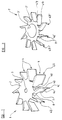
- a first air guiding device embodying the invention comprises a planar central hub plate 2 formed with a circular hole 3 at its centre for receiving an air filter closure securing bolt.
- Vanes 4 extend outwardly and downwardly from the periphery of the hub plate 2 at equally spaced apart locations around the periphery.
- Each vane 4 comprises a spoke portion 4a, a blade portion 4b and a lip portion 4c.
- the spoke portion 4a is coplanar with the hub plate 2 and extends outwardly from the periphery of the hub plate 2 at an angle of approximately 45° to the radial direction as shown in Figure 1.
- the blade portion 4b extends downwardly from one edge of the spoke portion 4a and lies substantially perpendicular to the plane of the hub plate 2 and terminates at its lower edge in the lip portion 4c which projects from the blade portion parallel to the spoke portion 4a on the other side of the blade portion from the spoke portion.
- the blade portion 4b is cut away at its lower radially innermost corner, so that the radially innermost edge 7 of the blade portion is shorter than its radially outermost edge and the lower edge of the blade portion is shorter than its upper edge.
- the radially innermost edge 7 of the blade portion 4b of each vane 4i is provided with a tab or deflector 8 which lies substantially tangential to the plate hub 2 and substantially perpendicular to an adjacent leading vane 4ii and substantially parallel with an adjacent following vane 4iii.
- the tab 8 is of a generally triangular shape, although this tab 8 may, of course, have any suitable shape as may the vanes 4.
- the air guiding device of Figure 1 is shown with ten vanes 4 and tabs 8, but other embodiments can be formed with more, or fewer, vanes 4 and tabs 8.
- ten vanes 4 are each provided with a respective tab 8.
- the tabs 8 are each angled at approximately 135° to their respective vane 4.
- the air guiding device 1 of Figure 1 is cut and formed from a single thin metal sheet, although the device could be made in other ways, such as by moulding or casting the device or by assembling the device from a number of discrete components.
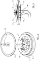
- the air guiding system 1 is installed in the central well area of a standard annular air filter 9 within the filter element.
- the hole 3 of the air guiding device receives an air filter closure securing bolt 10 which protrudes from the base of the air filter 9.
- the bolt 10 passes through the hole 3 and is used to locate an air filter closure 11 upon the air filter 9.
- the closure 11 is secured to the air filter 9 by means of a butterfly nut 12 or the like.
- the air guiding system 1 is also firmly located in the air filter 9.
- the vanes 4 of the air guiding device 1 are positioned in the air filter 9 so as to be at a tangent to the entrance of an inlet manifold 13 leading to a carburettor 14.
- the air guiding device 1' shown in Figure 3 is similar to that shown in Figure 1 and operates in an identical fashion but is of a flatter design to enable the air guiding device 1' to fit under the filter element of an air filter 9' of a conical type as shown in Figure 5.
- the air guiding device 1' of Figure 3 is also provided with small tabs 8 on the radially innermost edge of each vane 4 and the function of these will be discussed later.
- the general fan shape of the air guiding devices 1, 1' shown in Figures 1 and 3 means that air passing through the filters 9, 9' is travelling radially inwardly and parallel to the plane of the hub plate 2 as it enters the air guiding device.
- the air impinges on the vanes 4, 4' of the air guiding system 1, 1' and is deflected toward the narrow opening defined between the radially innermost edge of each vane 4, 4' and the rear face of the adjacent leading vane 4ii, 4ii' and then drawn downwardly towards the carburettor 14.
- the operation of the air guiding devices 1, 1' shown in Figures 1 and 3, is significantly improved for low air flow rates by the tabs 8, 8' provided on the radially innermost edges of the vanes 4, 4'.
- the small tabs 8, 8' serve to deflect the air flow as it enters the narrow opening between the radially innermost edge of one vane 4i and the back of the adjacent leading vane 4ii thereby entering the space under the hub plate 2 tangentially to the circular hub plate 2.
- the air being drawn down towards the carburettor has a certain tangential velocity, resulting in a vortical or turbulent air flow which, as mentioned above, serves to provide better mixing of the fuel droplets with the air.
- the resultant air flow which has passed through the air guiding device 1, 1' may be turbulent and/or vortical.
- the tabs 8, 8' may, in an alternative embodiment of the air guiding device 1, 1' which is not shown in the drawings, be provided as projections from the hub plate 2 which projections extend downwardly adjacent the radially innermost edge of each vane 4, 4' but which are not formed as a part of each vane 4, 4' as shown in the embodiments illustrated in the drawings.
Landscapes
- Engineering & Computer Science (AREA)
- Chemical & Material Sciences (AREA)
- Combustion & Propulsion (AREA)
- Mechanical Engineering (AREA)
- General Engineering & Computer Science (AREA)
- Filtering Of Dispersed Particles In Gases (AREA)
- Harvester Elements (AREA)
- Platform Screen Doors And Railroad Systems (AREA)
- Air-Flow Control Members (AREA)
Abstract
Claims (7)
- Un dispositif de guidage d'air (1) pour produire un flux d'air tourbillonnaire et/ou turbulent dans une tubulaire d'admission, lequel dispositif comprend : une plaque de moyeu (2) ayant une périphérie externe ; une pluralité d'ailettes (4) supportée par la plaque de moyeu (2) et s'étendant vers l'extérieur depuis la périphérie externe de la plaque de moyeu (2) pour défléchir un flux d'air heurtant le dispositif (1) suivant une première direction pour créer un premier flux d'air tourbillonnaire et/ou turbulent ; une série d'ouvertures définie entre les bords (7) d'ailettes adjacentes (4) à la périphérie externe de la plaque de moyeu (2), et une patte (8) associée avec au moins l'une des ailettes (4) localisée sur le bord le plus intérieur radialement (7) d'une ailette (4) dans l'une des ouvertures avec un angle par rapport à l'ailette (4) pour défléchir le flux d'air suivant une deuxième direction pour créer un deuxième flux d'air tourbillonnaire et/ou turbulent à des débits de flux d'air faibles auxquels les ailettes (4) ne créeront pas un premier flux d'air sensiblement tourbillonnaire et/ou turbulent, l'agencement étant tel que le flux d'air heurtant le dispositif (1) est défléchi en un flux d'air tourbillonnaire et/ou turbulent par les ailettes (4) et/ou la patte ou les pattes (8).
- Un dispositif de guidage d'air conforme à la Revendication 1, dans lequel le dispositif (1) est localisé de manière adjacente à une entrée de tubulure d'admission (13) tel que le flux d'air tourbillonnaire et/ou turbulent est tiré dans la tubulure d'admission (13).
- Un dispositif de guidage d'air conforme à la Revendication 1 ou 2, dans lequel la plaque de moyeu (2) est sensiblement circulaire et les ailettes (4) s'étendent vers l'extérieur depuis la périphérie externe de la plaque de moyeu (2) avec un angle sensiblement de 45° par rapport à la direction radiale.
- Un dispositif de guidage d'air conforme à une quelconque Revendication précédente, dans lequel la ou chaque patte (8) est disposée à 135° approximativement par rapport à l'ailette associée (4).
- Un dispositif de guidage d'air conforme à une quelconque revendication précédente, dans lequel chaque ailette (4) est munie d'une patte (8).
- Un dispositif de guidage d'air conforme à une quelconque revendication précédente, dans lequel le dispositif (1) est localisé dans un filtre à air annulaire (9).
- Un dispositif de guidage d'air conforme à l'une quelconque des Revendications 1 à 6, dans lequel le dispositif (1) est interposé entre un filtre à air (9) et une entrée de tubulure d'admission (13).
Applications Claiming Priority (5)
| Application Number | Priority Date | Filing Date | Title |
|---|---|---|---|
| MYPI9300243 | 1993-02-13 | ||
| MY9300243 | 1993-02-13 | ||
| GB9313949A GB2275081B (en) | 1993-02-13 | 1993-07-06 | An air guiding device |
| GB9313949 | 1993-07-06 | ||
| PCT/GB1994/000236 WO1994018448A1 (fr) | 1993-02-13 | 1994-02-08 | Dispositif de guidage d'air |
Publications (2)
| Publication Number | Publication Date |
|---|---|
| EP0683860A1 EP0683860A1 (fr) | 1995-11-29 |
| EP0683860B1 true EP0683860B1 (fr) | 1997-10-08 |
Family
ID=26303194
Family Applications (1)
| Application Number | Title | Priority Date | Filing Date |
|---|---|---|---|
| EP94905809A Expired - Lifetime EP0683860B1 (fr) | 1993-02-13 | 1994-02-08 | Dispositif de guidage d'air |
Country Status (6)
| Country | Link |
|---|---|
| US (1) | US5595157A (fr) |
| EP (1) | EP0683860B1 (fr) |
| CN (1) | CN1122625A (fr) |
| AU (1) | AU673896B2 (fr) |
| DE (1) | DE69406109T2 (fr) |
| WO (1) | WO1994018448A1 (fr) |
Families Citing this family (15)
| Publication number | Priority date | Publication date | Assignee | Title |
|---|---|---|---|---|
| US6796296B2 (en) * | 2002-06-05 | 2004-09-28 | Jay S. Kim | Fluid swirling device for an internal combustion engine |
| US5947081A (en) * | 1997-08-12 | 1999-09-07 | Kim; Sei Y. | Air flow system for internal combustion engine |
| US6267006B1 (en) | 1997-10-17 | 2001-07-31 | Ford Motor Company | Air induction assembly for a mass air flow sensor |
| US6041753A (en) * | 1998-06-11 | 2000-03-28 | Industrial Technology Research Institute, China Motor Corporation | Intake swirl enhancing structure for internal combustion engine |
| US6158412A (en) * | 1999-09-21 | 2000-12-12 | Kim; Jay S. | Air turbulence generator of internal combustion engines |
| KR200279840Y1 (ko) * | 2002-01-28 | 2002-06-28 | 김세영 | 내연기관의 흡배기 회전장치용 날개 |
| RU2237821C2 (ru) * | 2002-12-19 | 2004-10-10 | Никитин Митрофан Алексеевич | Устройство для подачи горючей смеси в цилиндры двигателя внутреннего сгорания и выпуска отработавших газов |
| US6752124B1 (en) * | 2003-04-30 | 2004-06-22 | Chin-Feng Chang | Eddy flow generator to increase horsepower of an internal combustion engine |
| US20040231304A1 (en) * | 2003-05-21 | 2004-11-25 | Wang Yi Ping | Increased flow air filter |
| US7086498B2 (en) * | 2003-08-25 | 2006-08-08 | Ford Global Technologies, Llc | Noise attenuation device for a vehicle exhaust system |
| US7131514B2 (en) * | 2003-08-25 | 2006-11-07 | Ford Global Technologies, Llc | Noise attenuation device for a vehicle exhaust system |
| JP4397943B2 (ja) * | 2007-08-24 | 2010-01-13 | トヨタ紡織株式会社 | 旋回流発生装置 |
| US9504947B2 (en) | 2012-11-13 | 2016-11-29 | Cummins Filtration Ip, Inc. | Air filter assemblies and carrier frames having vortex-generating flow guide |
| US20140338768A1 (en) * | 2013-05-15 | 2014-11-20 | Mario Marcic | Device For Inducing A Vortical Fluid Flow |
| KR102842780B1 (ko) * | 2024-09-05 | 2025-08-04 | 최진규 | 내연기관의 유체 흐름 조절 장치 |
Family Cites Families (18)
| Publication number | Priority date | Publication date | Assignee | Title |
|---|---|---|---|---|
| FR337921A (fr) * | 1903-12-21 | 1904-05-03 | Henri Joseph Ernest Hennebutte | Carburateur pour moteurs à gaz tonnants avec alimentation de pétrole ou autre hydrocarbure |
| GB239762A (en) * | 1924-12-24 | 1925-09-17 | Samuel Richard Bailey | An improved atomiser for use in internal combustion engines |
| GB239817A (en) * | 1925-06-12 | 1925-09-17 | Samuel Richard Bailey | An improved atomiser for use in internal combustion engines |
| GB309362A (en) * | 1928-08-29 | 1929-04-11 | Hans Brandl | Improvements in charge-mixing devices for internal combustion engines |
| FR697336A (fr) * | 1930-06-13 | 1931-01-15 | Appareil pour réduire la consommation d'essence d'un moteur d'automobile | |
| US1969202A (en) * | 1930-11-05 | 1934-08-07 | Bugaud Charles | Fuel vaporizing device |
| GB444020A (en) * | 1934-09-07 | 1936-03-09 | Josef Rugel | Improvements in heavy oil carburettors |
| DE2219982A1 (de) * | 1972-04-24 | 1973-11-08 | Fahr Ag Maschf | Verbrennungs-gemisch-regler fuer ottomotoren |
| FR2265997A1 (fr) * | 1974-03-29 | 1975-10-24 | Reissmueller Anton | |
| US4116187A (en) * | 1977-08-29 | 1978-09-26 | Moore Randall J | Apparatus for increasing the blend and charge of the fuel-air mixture for an engine |
| JPS55139252U (fr) * | 1979-03-27 | 1980-10-04 | ||
| US4417562A (en) * | 1981-06-08 | 1983-11-29 | Dalke Arthur E | Carburetor mixture control apparatus |
| JPS5813122A (ja) * | 1981-07-13 | 1983-01-25 | Masanobu Yoshida | 内燃機関における吸排気の渦流発生装置 |
| US4671247A (en) * | 1986-02-26 | 1987-06-09 | Barbee William E | Fuel atomizing apparatus for internal combustion engines |
| US4729776A (en) * | 1987-02-09 | 1988-03-08 | Elliff Howard E | Air swirling device for use in the annular space of air filters on internal combustion engines |
| US5137005A (en) * | 1990-03-06 | 1992-08-11 | Kirby Ronald A | Rotary fuel distributor system for an internal combustion engine |
| KR920004745Y1 (ko) * | 1990-06-12 | 1992-07-18 | 김세영 | 내연기관의 흡배기 회전장치 |
| WO1994005906A1 (fr) * | 1992-09-03 | 1994-03-17 | Suk Ju Yoon | Dispositif destine a augmenter le rendement du moteur a combustion interne d'un vehicule |
-
1994
- 1994-02-08 EP EP94905809A patent/EP0683860B1/fr not_active Expired - Lifetime
- 1994-02-08 WO PCT/GB1994/000236 patent/WO1994018448A1/fr not_active Ceased
- 1994-02-08 US US08/505,176 patent/US5595157A/en not_active Expired - Fee Related
- 1994-02-08 DE DE69406109T patent/DE69406109T2/de not_active Expired - Fee Related
- 1994-02-08 CN CN94191591A patent/CN1122625A/zh active Pending
- 1994-02-08 AU AU59769/94A patent/AU673896B2/en not_active Ceased
Also Published As
| Publication number | Publication date |
|---|---|
| DE69406109D1 (de) | 1997-11-13 |
| US5595157A (en) | 1997-01-21 |
| AU5976994A (en) | 1994-08-29 |
| CN1122625A (zh) | 1996-05-15 |
| WO1994018448A1 (fr) | 1994-08-18 |
| DE69406109T2 (de) | 1998-02-05 |
| EP0683860A1 (fr) | 1995-11-29 |
| AU673896B2 (en) | 1996-11-28 |
Similar Documents
| Publication | Publication Date | Title |
|---|---|---|
| AU673896B2 (en) | An air guiding device | |
| US6158412A (en) | Air turbulence generator of internal combustion engines | |
| US5113838A (en) | Air flow system for an internal combustion engine | |
| AU2003206165B2 (en) | Wing structure of air swirling device for internal combustion engine | |
| GB2133323A (en) | Air cleaning device | |
| US6840212B2 (en) | Wing structure of air swirling device for internal combustion engine | |
| AU2003206165A1 (en) | Wing structure of air swirling device for internal combustion engine | |
| CA2144969A1 (fr) | Pavillon d'aspiration de ventilateur centrifuge | |
| US4463742A (en) | Fuel enconomizer | |
| JPH06229339A (ja) | 空気流の一部を分岐する燃焼空気ダクトをもつ冷却気送風装置 | |
| EP0585105A1 (fr) | Moteur à combustion interne avec récirculation des gaz d'échappement | |
| US4359035A (en) | Intake manifold fuel atomizing screen | |
| US5323753A (en) | Induction system for an internal combustion engine | |
| US4015574A (en) | Apparatus for improving fuel-air mixture | |
| GB2275081A (en) | Turbulence creating air guiding device | |
| US5549085A (en) | Deflector insert for air filters | |
| WO1994005906A1 (fr) | Dispositif destine a augmenter le rendement du moteur a combustion interne d'un vehicule | |
| US4809512A (en) | Air-fuel injection system for a turbojet engine | |
| US4485795A (en) | Turbo gas atomizer | |
| GB2028488A (en) | Gas Turbine | |
| CN220706029U (zh) | 一种带有集流器的离心风轮 | |
| RU2209335C1 (ru) | Устройство для гомогенизации топливовоздушной смеси в двигателе внутреннего сгорания | |
| KR940003537B1 (ko) | 내연기관의 흡기 가속유도장치 | |
| KR200263051Y1 (ko) | 내연기관 흡배기 회전장치용 날개 | |
| SU1596121A1 (ru) | Гомогенизатор дл карбюраторного двигател внутреннего сгорани |
Legal Events
| Date | Code | Title | Description |
|---|---|---|---|
| PUAI | Public reference made under article 153(3) epc to a published international application that has entered the european phase |
Free format text: ORIGINAL CODE: 0009012 |
|
| 17P | Request for examination filed |
Effective date: 19950814 |
|
| AK | Designated contracting states |
Kind code of ref document: A1 Designated state(s): DE FR IT |
|
| RAP1 | Party data changed (applicant data changed or rights of an application transferred) |
Owner name: SIEW, SEOK HWA |
|
| GRAG | Despatch of communication of intention to grant |
Free format text: ORIGINAL CODE: EPIDOS AGRA |
|
| 17Q | First examination report despatched |
Effective date: 19961220 |
|
| GRAH | Despatch of communication of intention to grant a patent |
Free format text: ORIGINAL CODE: EPIDOS IGRA |
|
| GRAH | Despatch of communication of intention to grant a patent |
Free format text: ORIGINAL CODE: EPIDOS IGRA |
|
| GRAA | (expected) grant |
Free format text: ORIGINAL CODE: 0009210 |
|
| AK | Designated contracting states |
Kind code of ref document: B1 Designated state(s): DE FR IT |
|
| ITF | It: translation for a ep patent filed | ||
| REF | Corresponds to: |
Ref document number: 69406109 Country of ref document: DE Date of ref document: 19971113 |
|
| ET | Fr: translation filed | ||
| PLBE | No opposition filed within time limit |
Free format text: ORIGINAL CODE: 0009261 |
|
| STAA | Information on the status of an ep patent application or granted ep patent |
Free format text: STATUS: NO OPPOSITION FILED WITHIN TIME LIMIT |
|
| 26N | No opposition filed | ||
| PGFP | Annual fee paid to national office [announced via postgrant information from national office to epo] |
Ref country code: FR Payment date: 20010226 Year of fee payment: 8 |
|
| PGFP | Annual fee paid to national office [announced via postgrant information from national office to epo] |
Ref country code: DE Payment date: 20010306 Year of fee payment: 8 |
|
| PG25 | Lapsed in a contracting state [announced via postgrant information from national office to epo] |
Ref country code: DE Free format text: LAPSE BECAUSE OF NON-PAYMENT OF DUE FEES Effective date: 20020903 |
|
| PG25 | Lapsed in a contracting state [announced via postgrant information from national office to epo] |
Ref country code: FR Free format text: LAPSE BECAUSE OF NON-PAYMENT OF DUE FEES Effective date: 20021031 |
|
| REG | Reference to a national code |
Ref country code: FR Ref legal event code: ST |
|
| PG25 | Lapsed in a contracting state [announced via postgrant information from national office to epo] |
Ref country code: IT Free format text: LAPSE BECAUSE OF NON-PAYMENT OF DUE FEES Effective date: 20050208 |