EP0684183A2 - Procédé de fabrication de boîtes à parois mince. - Google Patents
Procédé de fabrication de boîtes à parois mince. Download PDFInfo
- Publication number
- EP0684183A2 EP0684183A2 EP95104649A EP95104649A EP0684183A2 EP 0684183 A2 EP0684183 A2 EP 0684183A2 EP 95104649 A EP95104649 A EP 95104649A EP 95104649 A EP95104649 A EP 95104649A EP 0684183 A2 EP0684183 A2 EP 0684183A2
- Authority
- EP
- European Patent Office
- Prior art keywords
- deep drawing
- tool
- package
- shoulder
- neck
- Prior art date
- Legal status (The legal status is an assumption and is not a legal conclusion. Google has not performed a legal analysis and makes no representation as to the accuracy of the status listed.)
- Withdrawn
Links
Images







Classifications
-
- B—PERFORMING OPERATIONS; TRANSPORTING
- B21—MECHANICAL METAL-WORKING WITHOUT ESSENTIALLY REMOVING MATERIAL; PUNCHING METAL
- B21D—WORKING OR PROCESSING OF SHEET METAL OR METAL TUBES, RODS OR PROFILES WITHOUT ESSENTIALLY REMOVING MATERIAL; PUNCHING METAL
- B21D22/00—Shaping without cutting, by stamping, spinning, or deep-drawing
- B21D22/20—Deep-drawing
- B21D22/26—Deep-drawing for making peculiarly, e.g. irregularly, shaped articles
-
- B—PERFORMING OPERATIONS; TRANSPORTING
- B65—CONVEYING; PACKING; STORING; HANDLING THIN OR FILAMENTARY MATERIAL
- B65D—CONTAINERS FOR STORAGE OR TRANSPORT OF ARTICLES OR MATERIALS, e.g. BAGS, BARRELS, BOTTLES, BOXES, CANS, CARTONS, CRATES, DRUMS, JARS, TANKS, HOPPERS, FORWARDING CONTAINERS; ACCESSORIES, CLOSURES, OR FITTINGS THEREFOR; PACKAGING ELEMENTS; PACKAGES
- B65D1/00—Rigid or semi-rigid containers having bodies formed in one piece, e.g. by casting metallic material, by moulding plastics, by blowing vitreous material, by throwing ceramic material, by moulding pulped fibrous material or by deep-drawing operations performed on sheet material
- B65D1/02—Bottles or similar containers with necks or like restricted apertures, designed for pouring contents
-
- B—PERFORMING OPERATIONS; TRANSPORTING
- B65—CONVEYING; PACKING; STORING; HANDLING THIN OR FILAMENTARY MATERIAL
- B65D—CONTAINERS FOR STORAGE OR TRANSPORT OF ARTICLES OR MATERIALS, e.g. BAGS, BARRELS, BOTTLES, BOXES, CANS, CARTONS, CRATES, DRUMS, JARS, TANKS, HOPPERS, FORWARDING CONTAINERS; ACCESSORIES, CLOSURES, OR FITTINGS THEREFOR; PACKAGING ELEMENTS; PACKAGES
- B65D17/00—Rigid or semi-rigid containers specially constructed to be opened by cutting or piercing, or by tearing of frangible members or portions
- B65D17/02—Rigid or semi-rigid containers specially constructed to be opened by cutting or piercing, or by tearing of frangible members or portions of curved cross-section, e.g. cans of circular or elliptical cross-section
Definitions
- the invention is a method of forming a slim container, especially a body, a shoulder, a neck and a forehead from a sheet of metal or steel, especially aluminum film or sheet steel.
- the invention includes a slim container, a body, a shoulder, a neck with a forehead shown, as well as a deep drawing tool, and a tool for contour forming a disk.
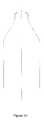
- the new product is a consumer package for beverages and liquid food products, especially for carbonated beverages, characterized particularly through a deep drawing method, preferred, with a cylinder formed side wall panel, which body is made of one and same material sheet, preferably of aluminum film or sheet steel connected with a conical package shoulder which same sheet material wall exceeds into a package forehead/pouring area.
- a circular separate end bottom lid is flanged onto the cylindrical package body's panel wall circle edge, forming a tight package bottom, before filling the packages.
- a pull-tab version with a complete package body, bottom up filling is required, before the bottom end is flanged on.
- the traditional cylinder formed can consisting of one entire and complete cylinder body, forming the package cylindrical wall panel which exceeds into one end of the package, made from the same sheet material, forming the package bottom.
- Know deep drawing technology for drawing the traditional can is not feasible for drawing a slim package, a wall, a shoulder, a neck with a forehead as required for the new package.
- a spray cans top consist of a separate forehead flanged onto a cylinder wall panel.
- the forehead/end is definitively not manufactured in a deep drawing process.
- the difference is more exposed in the spray cans cylindrical complete panel walls body, which has an overlap/end seem parallel to the length axis.
- an overlap/end seam is a weak area of a package wall, which produces fractions of the package inside coating lacquer during the different manufacturing processes, resulting in a rich environment for microorganisms to develop.
- the objective with the new segmented deep drawing methodology is to be able to manufacture a package containing a cylindrical side panel wall, a shoulder, a neck and a forehead, as well as other slim containers in a practical, economical and commercial way with a deep drawing method for deep drawing one sheet metal or sheet steel, particularly aluminum film or sheet steel with low area weight with traditional drawing quality.
- a further objective for proposing a new deep drawing methodology, with a particular, high production speed, simple technology, is that the new proposed methodology produces the option for commercial preferences.
- the proposed new methodology according to Claim 1 produces the option for industrialized production of the new consumer liquid packaging.
- the new deep drawing method eliminates the spray cans body's panel overlap seam. Particularly for food packaging, including beverages this has substantial practical and commercial value as, these seam areas generally collect microorganisms, which germs over time in contact with some food types can have hazardous consequences for the consumers.
- the conical neck part of the package can be manufactured without braeakage of the film material.
- Aluminum film or sheet steel cannot be punched out to a cone with an angle required for a bottle shape the traditional way without material breakage.
- the traditional deep drawing method is only feasible in a vertical package axis direction with same drawing shape along the entire drawing axis. Deep drawing into a cone is impossible.
- Claim 1 proposed contour forming a sheet steel or a plane aluminum film, preferabl according to tests, for extending the material area in the package shoulder area to prevent material breakage during deep drawing in a next second tool station.
- Claim 1 proposed methodologies, deep drawing from a prior formed contour disk with at least two segment deep drawing tool with a separate final coning process of the cylindrical formed shoulder with steps, eliminates these problems and produces an option for a feasible solution.
- the drawing form is a positive form in which the film is deep drawn over by the deep drawing tool.
- Claim 1 Preferable in Claim 1 is that the different deep drawing strokes are worked out over one and the same deep drawing form which eliminates high costs and technical problems with multiple deep drawing tool stations.
- the new invention is based on to take advantage of the new segmented deep drawing tools which separate concentric segments are overlapping the prior segment as well as moving along the same axis as separate drawing tools. It is also preferable that at least one of the segmented drawing tools have a ring formed square view.
- the rings cylindrical form is characteristic for the package wall square view.
- the new deep drawing tool have advantages, according to following description, incorporated in the new proposed methodology.
- the new method can also generally be used in deep drawing.
- the different deep drawing segments are gradually moved one after each other in the drawing direction, until all drawing tools have reached their end position.
- the drawing tools foreheads does not produce an even level in their end positions, and the body with the drawing tools in their end position exposes at least one shoulder section.
- a contour disk with a concentric formed ring-structure are stamped out from a plane circular aluminum film or particularly a sheet steel disk between a female and a male contour form, alternatively for material i.e. aluminum film with low degree of ductility, a second version, a circular twin head drawing process are preferred which gradually and more gently forms the material to the proposed contour with extended area. The purpose is to extend the material area of the disk.
- At least one section of the stepped formed cylinder shoulder are compressed between a male and female cone in at least one station, or in a spin necker, with a rotating wheel, to a smooth shoulder cone.
- the package forehead is formed out of one piece material sheet including a neck, a shoulder, and a panel wall.
- a circle can alternatively be locked out in the center of the forehead for later to pour the liquid out of the package.
- the new in one piece version package body makes the traditional two piece version with a separate package top mounted to a cylindrical package wall with an end seem redundant.
- the package panel wall and the neck are cylindrical formed, and that the shoulder has a cone form.
- This development produces a number of advantages: First, compared with i.e. a square view rectangular package walls, the traditional can, for the new invention, have a substantial lower material consumption, for several reasons. Second, a cylindrical deep drawn wall has a considerably lower degree of a contamination than a package with an end seam. Third, this version has the same practicality and hygiene in use as traditional glass bottle, preferable for consumer acceptance.
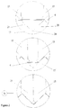
- FIG. 1 explaining a circular drawing process in vertical and horizontal view.
- This method is particular actual for sheet materials with low ductility properties, i.e. aluminum.
- Figure 2 exposes a vertical view of the drawing section, operating in three different situations during the circular drawing.
- the drawing process is finalized as the two drawing tools 15 have reached its final drawing position (24) with and extended film 6 material area of about 40%.
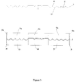
- Figure 3 is explaining the contour stamping process in a vertical view.
- a forming tool consisting of six separate tools 58, 58a, 59, 59a, 60, 60a, all tools are moving after the same axis.
- Tool 58 is a center tool overlapped by middle tool 59 which again is overlapped by outer tool 60. All tools have an over tool, a.
- a plane circular material disk sheet 6 is placed between tools 58, 59, 60 and 58a, 59a, 60a.
- Tools 58 and 58a are stamping together simultaneously with tool 60 and 60a in a first stroke which continues in holding position until second stamping stroke with tools 59 and 59a have been worked out.
- the Objective with this two stroke punching method is to prevent the center disk area 58 to stretch and firmly holding the disk circle edge in area 60 in a second stroke during stretching the material in area 59 to a contour structure. Different other structures can be stretched in the tool 59 area.
- This method is actual for sheet material with medium ductility properties, particularly sheet steel.
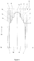
- Figure 4 is explaining a schematic development of the prior formed film disk 6 in the different drawing tools; 45, 46, 47, 48, 49. According to fig. 6a-6f, the film disk 6 is moving with each drawing segment until the drawing process is finalized with drawing tool 44.
- FIG. 5 is an example of the deep drawing process according to Claim 1.
- the deep drawing form 40 is a cylindrical positive form, over which the deep drawing tool 44 is drawing the film 6.
- the segments 45, 46, 47, 48, are moved in drawing direction 270, in a first stroke until the center tool 48 reaches its final stroke, simultaneously the forehead of the drawing segments 50, 51, 52, 53, are leveled and forehead 53 reaches the center tool 48.
- the drawing tools 45, 46, 47, reaches their respective corresponding foreheads 50, 51, 52 in continuing strokes.
- the mandrel 40 forehead has a form 43, imprinting the package forehead 9 and tool 48 center has incorporated a circle imprinting scoring tool, with the result that not only the neck 5 and a part of the shoulder 4 of the package 2 will be drawn in the first stroke, but also a form 9 with an outside score are stamped out in the first stroke.
- the drawing tools 45, 46, 47 are moved in operation direction 270 until its final position 52a were the forehead of drawing tool 47 is forming a second segment of the package body.
- the foreheads 50, 51, 52, of the three drawing tools 45, 46, 47 is again leveled.
- Figure 6 is another variation of the method explained under figure 5.
- a so called 0 stroke is punching out a circle area in the forehead 43 for pouring the liquid out of the final package, a screw cap version.
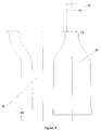
- Figure 8 is a principle drawing of a coning process to shrink a segment formed package body.
- a package body 6 is compressed between a coning tool 54 and coning mandrel 55 along the same axis to cone the prior formed steps produced in the segmented deep drawing process.
- the coning process may bee fulfilled after the same principle with different cone grades in different tool stations, alternatively compressed air can replace the mandrel 55.
- Figure 9 is a principle drawing of a circular spin neck and flanging operation.
- the segment formed package body 6 are pushed onto a mandrel 80 which starts rotating after the package body 6 have entered onto the mandrel and are rotating around its own axis on a carousel.
- a spin neck wheel 81 with an imprint contour negative corresponding with the final package body and a circumference 4, 6, 8 or 10 times larger the package neck 5 in the corresponding neck (5) area are moving gradually from point 180 to point 0 and producing the final shoulder (4) and neck (5), and an end neck flanger 82 are gradually moving from point 90 to 270 to flange the top and the bottom of the package.
Landscapes
- Engineering & Computer Science (AREA)
- Mechanical Engineering (AREA)
- Ceramic Engineering (AREA)
- Containers Having Bodies Formed In One Piece (AREA)
Applications Claiming Priority (4)
| Application Number | Priority Date | Filing Date | Title |
|---|---|---|---|
| DE19944411337 DE4411337A1 (de) | 1994-03-30 | 1994-03-30 | Verfahren zum Formen eines schlanken Behälters, Behälter und Tiefziehwerkzeug |
| DE4411337 | 1994-03-30 | ||
| DE4423864 | 1994-07-06 | ||
| DE4423864 | 1994-07-06 |
Publications (2)
| Publication Number | Publication Date |
|---|---|
| EP0684183A2 true EP0684183A2 (fr) | 1995-11-29 |
| EP0684183A3 EP0684183A3 (fr) | 1996-11-20 |
Family
ID=25935287
Family Applications (1)
| Application Number | Title | Priority Date | Filing Date |
|---|---|---|---|
| EP95104649A Withdrawn EP0684183A3 (fr) | 1994-03-30 | 1995-03-29 | Procédé de fabrication de boîtes à parois mince. |
Country Status (1)
| Country | Link |
|---|---|
| EP (1) | EP0684183A3 (fr) |
Cited By (7)
| Publication number | Priority date | Publication date | Assignee | Title |
|---|---|---|---|---|
| WO2015004908A1 (fr) * | 2013-07-09 | 2015-01-15 | Jfeスチール株式会社 | Procédé de moulage de plaque et procédé de définition de forme moulée préliminaire |
| USD742251S1 (en) | 2014-07-16 | 2015-11-03 | Ball Corporation | Two-piece contoured metallic container |
| USD758207S1 (en) | 2014-08-08 | 2016-06-07 | Ball Corporation | Two-piece contoured metallic container |
| US10239648B2 (en) | 2014-10-28 | 2019-03-26 | Ball Metalpack, Llc | Apparatus and method for forming a cup with a reformed bottom |
| US10315242B2 (en) | 2014-10-15 | 2019-06-11 | Ball Metalpack, Llc | Apparatus and method for simultaneously forming a contoured shoulder and neck portion in a closed end of a metallic container |
| USD1043246S1 (en) | 2022-08-05 | 2024-09-24 | Ball Corporation | Bottle |
| USD1047693S1 (en) | 2020-06-09 | 2024-10-22 | Ball Corporation | Metal bottle |
Families Citing this family (1)
| Publication number | Priority date | Publication date | Assignee | Title |
|---|---|---|---|---|
| USD804309S1 (en) | 2016-02-17 | 2017-12-05 | Ball Corporation | Metal bottle |
Family Cites Families (7)
| Publication number | Priority date | Publication date | Assignee | Title |
|---|---|---|---|---|
| FR785453A (fr) * | 1934-02-10 | 1935-08-10 | Steyr Werke A G | Procédé et dispositif pour la fabrication de récipients ouverts d'un côté |
| US2359775A (en) * | 1940-03-26 | 1944-10-10 | Crown Cork & Seal Co | Method of making containers |
| FR93556E (fr) * | 1966-04-21 | 1969-04-18 | Outil De Bondy & Sopem Reunis | Procédé d'emboutissage notamment pour la réalisation de récipients profonds a partir de feuilles métalliques minces ainsi que les articles conformes a ceux obtenus ou procédé similaire. |
| BE790570A (fr) * | 1971-10-27 | 1973-02-15 | Alusuisse | Boite aerosol |
| DE2451511C3 (de) * | 1974-10-30 | 1981-03-26 | Friedrich Wilhelm Ing.(grad.) 5880 Lüdenscheid Bracht | Verfahren und Vorrichtung zum Tiefziehen von Behältern aus Metall- oder Verbundfolie |
| US4111032A (en) * | 1974-11-06 | 1978-09-05 | Societe Lorraine De Laminage Continu | Process for producing a metal sheet to be deep drawn or extra-deep drawn for the fabrication of shaped metal parts |
| JPH02179325A (ja) * | 1988-12-29 | 1990-07-12 | Enami Seiki:Kk | 絞り成形機 |
-
1995
- 1995-03-29 EP EP95104649A patent/EP0684183A3/fr not_active Withdrawn
Cited By (8)
| Publication number | Priority date | Publication date | Assignee | Title |
|---|---|---|---|---|
| WO2015004908A1 (fr) * | 2013-07-09 | 2015-01-15 | Jfeスチール株式会社 | Procédé de moulage de plaque et procédé de définition de forme moulée préliminaire |
| US10730090B2 (en) | 2013-07-09 | 2020-08-04 | Jfe Steel Corporation | Method for forming blank and method for determining preforming shape |
| USD742251S1 (en) | 2014-07-16 | 2015-11-03 | Ball Corporation | Two-piece contoured metallic container |
| USD758207S1 (en) | 2014-08-08 | 2016-06-07 | Ball Corporation | Two-piece contoured metallic container |
| US10315242B2 (en) | 2014-10-15 | 2019-06-11 | Ball Metalpack, Llc | Apparatus and method for simultaneously forming a contoured shoulder and neck portion in a closed end of a metallic container |
| US10239648B2 (en) | 2014-10-28 | 2019-03-26 | Ball Metalpack, Llc | Apparatus and method for forming a cup with a reformed bottom |
| USD1047693S1 (en) | 2020-06-09 | 2024-10-22 | Ball Corporation | Metal bottle |
| USD1043246S1 (en) | 2022-08-05 | 2024-09-24 | Ball Corporation | Bottle |
Also Published As
| Publication number | Publication date |
|---|---|
| EP0684183A3 (fr) | 1996-11-20 |
Similar Documents
| Publication | Publication Date | Title |
|---|---|---|
| US6082944A (en) | Resealable beverage container and top therefor | |
| US5704240A (en) | Method and apparatus for forming threads in metal containers | |
| US5014536A (en) | Method and apparatus for drawing sheet metal can stock | |
| US5622070A (en) | Method of forming a contoured container | |
| EP2119515B1 (fr) | Procédé de fabrication d'une boîte aérosol en aluminium | |
| US6386013B1 (en) | Container end with thin lip | |
| JP3754076B2 (ja) | ねじ付きアルミニウム缶およびその製造方法 | |
| MX2007001125A (es) | Metodo y aparato para formar un cierre metalico del extremo de un contenedor. | |
| WO2002087800A1 (fr) | Procedes de formage par giration de contenants initialement cylindriques et analogues | |
| US7185525B2 (en) | Method and container having reinforcing rib structures | |
| GB2213082A (en) | Method and apparatus for forming tall tapered containers | |
| US4646930A (en) | Bottom profile for a seamless container body | |
| US4184444A (en) | Tapered plastic container with seamed metal end and method for making it | |
| US3362563A (en) | Frangible closure cap | |
| US20030132188A1 (en) | Threading method of a metallic bottle | |
| EP0512984B1 (fr) | Procede et appareil de traitement de conteneurs | |
| BG107409A (bg) | Капсули за затваряне с листова пола | |
| RU2164887C1 (ru) | Банка для продуктов и способ ее изготовления | |
| US5820326A (en) | Method and apparatus for making a tamper-evident crown | |
| EP1007426B1 (fr) | Recipient a boisson refermable et son couvercle | |
| US5263354A (en) | Drawn can body methods, apparatus and products | |
| JP4208511B2 (ja) | 缶体の胴部成形方法 | |
| US5199596A (en) | Drawn can body methods, apparatus and products | |
| WO2022070577A1 (fr) | Procédé de fabrication de récipient et dispositif de fabrication de récipient | |
| WO2005061149A2 (fr) | Procede et installation pour former un contenant metallique, et contenant metallique pour le stockage de produits alimentaires |
Legal Events
| Date | Code | Title | Description |
|---|---|---|---|
| PUAI | Public reference made under article 153(3) epc to a published international application that has entered the european phase |
Free format text: ORIGINAL CODE: 0009012 |
|
| AK | Designated contracting states |
Kind code of ref document: A2 Designated state(s): AT BE CH DK ES FR GB GR IT LI NL PT SE |
|
| RBV | Designated contracting states (corrected) |
Designated state(s): AT BE CH DK ES FR GB GR IT LI NL PT SE |
|
| REG | Reference to a national code |
Ref country code: DE Ref legal event code: 8566 |
|
| PUAL | Search report despatched |
Free format text: ORIGINAL CODE: 0009013 |
|
| AK | Designated contracting states |
Kind code of ref document: A3 Designated state(s): AT BE CH DK ES FR GB GR IT LI NL PT SE |
|
| 17P | Request for examination filed |
Effective date: 19970818 |
|
| STAA | Information on the status of an ep patent application or granted ep patent |
Free format text: STATUS: THE APPLICATION IS DEEMED TO BE WITHDRAWN |
|
| 18D | Application deemed to be withdrawn |
Effective date: 19971001 |