EP0684325A1 - Monocristal d'un grenat du type de fer-terre rare substitué par le bismuth à faible saturation de champ magnétique et son application - Google Patents
Monocristal d'un grenat du type de fer-terre rare substitué par le bismuth à faible saturation de champ magnétique et son application Download PDFInfo
- Publication number
- EP0684325A1 EP0684325A1 EP95107701A EP95107701A EP0684325A1 EP 0684325 A1 EP0684325 A1 EP 0684325A1 EP 95107701 A EP95107701 A EP 95107701A EP 95107701 A EP95107701 A EP 95107701A EP 0684325 A1 EP0684325 A1 EP 0684325A1
- Authority
- EP
- European Patent Office
- Prior art keywords
- single crystal
- bismuth
- rare earth
- magnetic field
- garnet single
- Prior art date
- Legal status (The legal status is an assumption and is not a legal conclusion. Google has not performed a legal analysis and makes no representation as to the accuracy of the status listed.)
- Withdrawn
Links
- XEEYBQQBJWHFJM-UHFFFAOYSA-N Iron Chemical compound [Fe] XEEYBQQBJWHFJM-UHFFFAOYSA-N 0.000 title claims abstract description 237
- 239000013078 crystal Substances 0.000 title claims abstract description 130
- 239000002223 garnet Substances 0.000 title claims abstract description 117
- 229910052742 iron Inorganic materials 0.000 title claims abstract description 96
- 229910052761 rare earth metal Inorganic materials 0.000 title claims description 98
- 150000002910 rare earth metals Chemical class 0.000 title claims description 92
- 229920006395 saturated elastomer Polymers 0.000 title abstract description 50
- 230000003287 optical effect Effects 0.000 claims abstract description 61
- 239000000758 substrate Substances 0.000 claims abstract description 44
- 238000000034 method Methods 0.000 claims abstract description 30
- 239000007791 liquid phase Substances 0.000 claims abstract description 8
- 229910052727 yttrium Inorganic materials 0.000 claims abstract description 8
- VWQVUPCCIRVNHF-UHFFFAOYSA-N yttrium atom Chemical compound [Y] VWQVUPCCIRVNHF-UHFFFAOYSA-N 0.000 claims abstract description 8
- 229910052765 Lutetium Inorganic materials 0.000 claims abstract description 7
- 229910052769 Ytterbium Inorganic materials 0.000 claims abstract description 7
- OHSVLFRHMCKCQY-UHFFFAOYSA-N lutetium atom Chemical compound [Lu] OHSVLFRHMCKCQY-UHFFFAOYSA-N 0.000 claims abstract description 7
- NAWDYIZEMPQZHO-UHFFFAOYSA-N ytterbium Chemical compound [Yb] NAWDYIZEMPQZHO-UHFFFAOYSA-N 0.000 claims abstract description 7
- 239000000126 substance Substances 0.000 claims description 15
- -1 4N) of 1660g Chemical compound 0.000 description 64
- 239000000155 melt Substances 0.000 description 41
- WMWLMWRWZQELOS-UHFFFAOYSA-N bismuth(iii) oxide Chemical compound O=[Bi]O[Bi]=O WMWLMWRWZQELOS-UHFFFAOYSA-N 0.000 description 26
- JKWMSGQKBLHBQQ-UHFFFAOYSA-N diboron trioxide Chemical compound O=BOB=O JKWMSGQKBLHBQQ-UHFFFAOYSA-N 0.000 description 26
- HTUMBQDCCIXGCV-UHFFFAOYSA-N lead oxide Chemical compound [O-2].[Pb+2] HTUMBQDCCIXGCV-UHFFFAOYSA-N 0.000 description 26
- BASFCYQUMIYNBI-UHFFFAOYSA-N platinum Chemical compound [Pt] BASFCYQUMIYNBI-UHFFFAOYSA-N 0.000 description 26
- CMIHHWBVHJVIGI-UHFFFAOYSA-N gadolinium(iii) oxide Chemical compound [O-2].[O-2].[O-2].[Gd+3].[Gd+3] CMIHHWBVHJVIGI-UHFFFAOYSA-N 0.000 description 25
- 239000013307 optical fiber Substances 0.000 description 15
- 229910000416 bismuth oxide Inorganic materials 0.000 description 13
- 229910052810 boron oxide Inorganic materials 0.000 description 13
- 150000001875 compounds Chemical class 0.000 description 13
- TYIXMATWDRGMPF-UHFFFAOYSA-N dibismuth;oxygen(2-) Chemical compound [O-2].[O-2].[O-2].[Bi+3].[Bi+3] TYIXMATWDRGMPF-UHFFFAOYSA-N 0.000 description 13
- AJNVQOSZGJRYEI-UHFFFAOYSA-N digallium;oxygen(2-) Chemical compound [O-2].[O-2].[O-2].[Ga+3].[Ga+3] AJNVQOSZGJRYEI-UHFFFAOYSA-N 0.000 description 13
- 229910001195 gallium oxide Inorganic materials 0.000 description 13
- QZQVBEXLDFYHSR-UHFFFAOYSA-N gallium(III) oxide Inorganic materials O=[Ga]O[Ga]=O QZQVBEXLDFYHSR-UHFFFAOYSA-N 0.000 description 13
- UQSXHKLRYXJYBZ-UHFFFAOYSA-N iron oxide Inorganic materials [Fe]=O UQSXHKLRYXJYBZ-UHFFFAOYSA-N 0.000 description 13
- JEIPFZHSYJVQDO-UHFFFAOYSA-N iron(III) oxide Inorganic materials O=[Fe]O[Fe]=O JEIPFZHSYJVQDO-UHFFFAOYSA-N 0.000 description 13
- 229910000464 lead oxide Inorganic materials 0.000 description 13
- NDLPOXTZKUMGOV-UHFFFAOYSA-N oxo(oxoferriooxy)iron hydrate Chemical compound O.O=[Fe]O[Fe]=O NDLPOXTZKUMGOV-UHFFFAOYSA-N 0.000 description 13
- 229910052697 platinum Inorganic materials 0.000 description 13
- 230000000694 effects Effects 0.000 description 12
- 229910001938 gadolinium oxide Inorganic materials 0.000 description 12
- 229940075613 gadolinium oxide Drugs 0.000 description 12
- SIWVEOZUMHYXCS-UHFFFAOYSA-N oxo(oxoyttriooxy)yttrium Chemical compound O=[Y]O[Y]=O SIWVEOZUMHYXCS-UHFFFAOYSA-N 0.000 description 11
- 229910052782 aluminium Inorganic materials 0.000 description 9
- 230000005415 magnetization Effects 0.000 description 9
- XAGFODPZIPBFFR-UHFFFAOYSA-N aluminium Chemical class [Al] XAGFODPZIPBFFR-UHFFFAOYSA-N 0.000 description 8
- 229910052733 gallium Inorganic materials 0.000 description 8
- GYHNNYVSQQEPJS-UHFFFAOYSA-N Gallium Chemical compound [Ga] GYHNNYVSQQEPJS-UHFFFAOYSA-N 0.000 description 7
- 230000000052 comparative effect Effects 0.000 description 6
- 238000002474 experimental method Methods 0.000 description 6
- 229910052797 bismuth Inorganic materials 0.000 description 5
- 230000003247 decreasing effect Effects 0.000 description 5
- 239000010408 film Substances 0.000 description 5
- 229910052688 Gadolinium Inorganic materials 0.000 description 4
- VEXZGXHMUGYJMC-UHFFFAOYSA-N Hydrochloric acid Chemical compound Cl VEXZGXHMUGYJMC-UHFFFAOYSA-N 0.000 description 4
- JCXGWMGPZLAOME-UHFFFAOYSA-N bismuth atom Chemical compound [Bi] JCXGWMGPZLAOME-UHFFFAOYSA-N 0.000 description 4
- 230000001747 exhibiting effect Effects 0.000 description 4
- UIWYJDYFSGRHKR-UHFFFAOYSA-N gadolinium atom Chemical compound [Gd] UIWYJDYFSGRHKR-UHFFFAOYSA-N 0.000 description 4
- 239000000463 material Substances 0.000 description 4
- 230000010287 polarization Effects 0.000 description 4
- 238000001816 cooling Methods 0.000 description 3
- 238000010586 diagram Methods 0.000 description 3
- 238000010438 heat treatment Methods 0.000 description 3
- PNEYBMLMFCGWSK-UHFFFAOYSA-N aluminium oxide Inorganic materials [O-2].[O-2].[O-2].[Al+3].[Al+3] PNEYBMLMFCGWSK-UHFFFAOYSA-N 0.000 description 2
- 238000004891 communication Methods 0.000 description 2
- 229910052593 corundum Inorganic materials 0.000 description 2
- JYTUFVYWTIKZGR-UHFFFAOYSA-N holmium oxide Inorganic materials [O][Ho]O[Ho][O] JYTUFVYWTIKZGR-UHFFFAOYSA-N 0.000 description 2
- 229910003443 lutetium oxide Inorganic materials 0.000 description 2
- TWNQGVIAIRXVLR-UHFFFAOYSA-N oxo(oxoalumanyloxy)alumane Chemical compound O=[Al]O[Al]=O TWNQGVIAIRXVLR-UHFFFAOYSA-N 0.000 description 2
- UZLYXNNZYFBAQO-UHFFFAOYSA-N oxygen(2-);ytterbium(3+) Chemical compound [O-2].[O-2].[O-2].[Yb+3].[Yb+3] UZLYXNNZYFBAQO-UHFFFAOYSA-N 0.000 description 2
- 239000004065 semiconductor Substances 0.000 description 2
- 230000008054 signal transmission Effects 0.000 description 2
- GWEVSGVZZGPLCZ-UHFFFAOYSA-N titanium dioxide Inorganic materials O=[Ti]=O GWEVSGVZZGPLCZ-UHFFFAOYSA-N 0.000 description 2
- 229910001845 yogo sapphire Inorganic materials 0.000 description 2
- 229910003454 ytterbium oxide Inorganic materials 0.000 description 2
- 229940075624 ytterbium oxide Drugs 0.000 description 2
- FIXNOXLJNSSSLJ-UHFFFAOYSA-N ytterbium(III) oxide Inorganic materials O=[Yb]O[Yb]=O FIXNOXLJNSSSLJ-UHFFFAOYSA-N 0.000 description 2
- 229910052771 Terbium Inorganic materials 0.000 description 1
- 238000004458 analytical method Methods 0.000 description 1
- 238000013459 approach Methods 0.000 description 1
- 239000000470 constituent Substances 0.000 description 1
- 230000007423 decrease Effects 0.000 description 1
- 230000007547 defect Effects 0.000 description 1
- 230000008021 deposition Effects 0.000 description 1
- 238000011161 development Methods 0.000 description 1
- 230000018109 developmental process Effects 0.000 description 1
- 230000020169 heat generation Effects 0.000 description 1
- OWCYYNSBGXMRQN-UHFFFAOYSA-N holmium(3+);oxygen(2-) Chemical compound [O-2].[O-2].[O-2].[Ho+3].[Ho+3] OWCYYNSBGXMRQN-UHFFFAOYSA-N 0.000 description 1
- 229910052738 indium Inorganic materials 0.000 description 1
- MPARYNQUYZOBJM-UHFFFAOYSA-N oxo(oxolutetiooxy)lutetium Chemical compound O=[Lu]O[Lu]=O MPARYNQUYZOBJM-UHFFFAOYSA-N 0.000 description 1
- 230000003252 repetitive effect Effects 0.000 description 1
- 229910052706 scandium Inorganic materials 0.000 description 1
- 238000000926 separation method Methods 0.000 description 1
- 229910052710 silicon Inorganic materials 0.000 description 1
- 238000004611 spectroscopical analysis Methods 0.000 description 1
- 238000006467 substitution reaction Methods 0.000 description 1
- GZCRRIHWUXGPOV-UHFFFAOYSA-N terbium atom Chemical compound [Tb] GZCRRIHWUXGPOV-UHFFFAOYSA-N 0.000 description 1
- 239000010409 thin film Substances 0.000 description 1
Images


Classifications
-
- H—ELECTRICITY
- H01—ELECTRIC ELEMENTS
- H01F—MAGNETS; INDUCTANCES; TRANSFORMERS; SELECTION OF MATERIALS FOR THEIR MAGNETIC PROPERTIES
- H01F10/00—Thin magnetic films, e.g. of one-domain structure
- H01F10/08—Thin magnetic films, e.g. of one-domain structure characterised by magnetic layers
- H01F10/10—Thin magnetic films, e.g. of one-domain structure characterised by magnetic layers characterised by the composition
- H01F10/18—Thin magnetic films, e.g. of one-domain structure characterised by magnetic layers characterised by the composition being compounds
- H01F10/20—Ferrites
- H01F10/24—Garnets
- H01F10/245—Modifications for enhancing interaction with electromagnetic wave energy
-
- C—CHEMISTRY; METALLURGY
- C30—CRYSTAL GROWTH
- C30B—SINGLE-CRYSTAL GROWTH; UNIDIRECTIONAL SOLIDIFICATION OF EUTECTIC MATERIAL OR UNIDIRECTIONAL DEMIXING OF EUTECTOID MATERIAL; REFINING BY ZONE-MELTING OF MATERIAL; PRODUCTION OF A HOMOGENEOUS POLYCRYSTALLINE MATERIAL WITH DEFINED STRUCTURE; SINGLE CRYSTALS OR HOMOGENEOUS POLYCRYSTALLINE MATERIAL WITH DEFINED STRUCTURE; AFTER-TREATMENT OF SINGLE CRYSTALS OR A HOMOGENEOUS POLYCRYSTALLINE MATERIAL WITH DEFINED STRUCTURE; APPARATUS THEREFOR
- C30B19/00—Liquid-phase epitaxial-layer growth
- C30B19/02—Liquid-phase epitaxial-layer growth using molten solvents, e.g. flux
-
- C—CHEMISTRY; METALLURGY
- C30—CRYSTAL GROWTH
- C30B—SINGLE-CRYSTAL GROWTH; UNIDIRECTIONAL SOLIDIFICATION OF EUTECTIC MATERIAL OR UNIDIRECTIONAL DEMIXING OF EUTECTOID MATERIAL; REFINING BY ZONE-MELTING OF MATERIAL; PRODUCTION OF A HOMOGENEOUS POLYCRYSTALLINE MATERIAL WITH DEFINED STRUCTURE; SINGLE CRYSTALS OR HOMOGENEOUS POLYCRYSTALLINE MATERIAL WITH DEFINED STRUCTURE; AFTER-TREATMENT OF SINGLE CRYSTALS OR A HOMOGENEOUS POLYCRYSTALLINE MATERIAL WITH DEFINED STRUCTURE; APPARATUS THEREFOR
- C30B29/00—Single crystals or homogeneous polycrystalline material with defined structure characterised by the material or by their shape
- C30B29/10—Inorganic compounds or compositions
- C30B29/16—Oxides
- C30B29/22—Complex oxides
- C30B29/28—Complex oxides with formula A3Me5O12 wherein A is a rare earth metal and Me is Fe, Ga, Sc, Cr, Co or Al, e.g. garnets
Definitions
- the present invention relates to a bismuth-substituted rare earth iron garnet single crystal used for a Faraday rotator. More particularly, the present invention relates to a low magnetic field bismuth-substituted rare earth iron garnet single crystal suited to a Faraday rotator for an optical switch using a magnet-optic effect, and to a magneto-optical type optical switch formed of the bismuth-substituted rare earth iron garnet single crystal.
- optical switch having a function of exchanging an optical signal or turning on/off the optical signal.
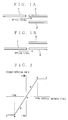
- optical switch which has been put into practice until now is an mechanical type optical switch as disclosed in Japanese Preliminary Publication No. 63-301918 (1988). Its schematic is shown in Figs. 1A and 1B.
- FIGs. 1A and 1B reference numerals 1, 2 and 3 denote optical fibers, respectively.
- an optical signal is being transferred from the optical fiber 1 to the optical fiber 2 (Fig. 1A).
- the optical fiber 1 is mechanically moved to a position opposite to the optical fiber 3 (Fig. 1B).
- the optical signal which has been transferred from the optical fiber 1 to the optical fiber 2 is now transferred to the optical fiber 3.
- This is a principle of the mechanical type optical switch.
- the structure of the mechanical type optical switch is very simple.
- the path (path A) from the optical fiber 1 to the optical fiber 3 is substantially completely separated from the path (path A) from the optical fiber 1 to the optical fiber 3. Therefore, the mechanical type optical switch has a manifest advantage of less crosstalk.
- the movable portion of the mechanical optical switch has a possibility of a slight change in its position owing to the repetitive operation for a long time. For this reason, where a single-mode optical fiber having a core diameter of about 10 ⁇ m, which is generally used as an optical fiber is used, a slight change in position leads to great signal transmission loss. Thus, the mechanical optical switch has a noticeable problem and defect in reliability.
- optical switch which requires no mechanical movable portion has been investigated.
- the optical switch which requires no mechanical movable portion, is excellent in reliability for a long time.
- the Faraday effect is a kind of the magneto-optic effect.
- the Faraday effect means a phenomenon that the polarized plane of light having permeated through a material exhibiting the Faraday effect, i.e., Faraday element (or Faraday rotator) rotates.
- the rotating angle of the polarized plane is proportional to the strength of magnetization in the Faraday element. Such a phenomenon is shown in Fig. 2.
- the Faraday rotating angle of the Faraday rotator with no external magnetic field (strength) applied is located at zero [0] or an origin o .
- the absolute value of the Faraday rotating angle ( ⁇ F or - ⁇ F , generally, plus in a clockwise rotation and minus in a counterclockwise rotation) increases gradually through path a or path d (path o ⁇ a ⁇ b or path o ⁇ d ⁇ e ).
- the Faraday rotating angle becomes a saturated value (saturated magnetic field: b or e point). Even when the external magnetic field strength further increases, since the Faraday rotating angle has already been saturated, it only shifts from b to c or from e to f with no change in the absolute value.
- the rotating angle follows a reverse path, i.e., c ⁇ b ⁇ a ⁇ o or f ⁇ e ⁇ d ⁇ o and returns to the origin o ).
- the basic operation of the magneto-optic type optical switch is to generate the magnetic field larger than the saturated points b and e in Fig. 2 in a magnetic field generating device so that the magnetic characteristic status of the Faraday rotator is changed or the direction of magnetization is reversed.
- FIG. 3 The basic structure of the optical switch using the Faraday rotator formed of e.g., bismuth-substituted rare earth iron garnet single crystal is such as shown in Fig. 3.
- reference numeral 4 designates a polarizer made of e.g., rutile; 5 a Faraday rotator; 6 a polarization separation element of e.g., rutile; and 7 a magnetic field generating device (made of an electromagnet) for generating a magnetic field enough to saturate the Faraday rotator magnetically, i.e., the magnetic field larger than saturated magnetic field.
- a polarizer made of e.g., rutile
- 5 a Faraday rotator
- 6 a polarization separation element of e.g., rutile
- 7 a magnetic field generating device (made of an electromagnet) for generating a magnetic field enough to saturate the Faraday rotator magnetically, i.e
- the light having permeated through the polarizer 4 becomes a linear polarized light which is incident on the Faraday rotator.
- the polarization plane of the light incident on the Faraday rotator rotates there.
- whether the rotating direction of the polarization plane is clockwise (plus) or counterclockwise (minus) depends on the direction of the magnetic field applied to the Faraday rotator.
- the optical path of the light which has permeated through the polarized light separating element 7 is also changed.
- the optical signal transmission path can be switched.
- the chemical composition of the bismuth-substituted rare earth iron garnet single crystal can be expressed by (LBi)3(FeM)5O12 (where L denotes yttrium (Y) or rare earth element, and M denotes an element such as Al, Ga, In, Si or Sc).
- L denotes yttrium (Y) or rare earth element
- M denotes an element such as Al, Ga, In, Si or Sc.
- the saturated magnetic field of the bismuth-substituted rare earth iron garnet single crystal depends on the kinds and concentrations of the constituent elements.
- terbium Tb and gadolinium Gd selected as a rare earth element and substitution of aluminum Al or gadolinium Gd substituted for part of iron can reduce the saturated magnetic field (Japanese Preliminary Publication No. 61-20926).
- the inventors of this application were interested in the magneto-optic effect of the bismuth-substituted rare earth iron garnet single crystal represented by a chemical equation (TbBi)3(FeGaAl)5O12 or (GdBi)3(FeGaAl)5O12 now presented, and first made detailed fundamental experiments in order to develop an optical switch using the Faraday effect.
- the result of the fundamental experiment thus obtained was contrary to expectations of the inventors.
- the bismuth-substituted rare earth iron garnet single crystal having a low saturated magnetic field involved two critical technical difficulties or problems.
- the first is a problems relative to inversion of the bismuth-substituted rare earth iron garnet single crystal having a low saturated magnetic field
- the second is a problem due to the temperature characteristic of this crystal.
- the bismuth-substituted rare earth iron garnet single crystal having a low saturated magnetic field exhibits a phenomenon that the magnetisation will not be inverted even when the magnetic field approximately equal to the saturated magnetic field is applied.
- the magnetization characteristic for an external magnetic field of the common bismuth-substituted rare earth iron garnet single crystal having a relatively large saturated magnetic field i.e., the relation between the external magnetic field strength and the Faraday rotating angle is such as shown in Fig. 2.
- the relation between the external magnetic field strength and the Faraday rotating angle draws a hysteresis loop such as a path o ⁇ a ⁇ b ⁇ c ⁇ b ⁇ b' ⁇ a ⁇ o as shown in Fig. 4.
- the path (o ⁇ a ⁇ b ⁇ c) when the strength of the external magnetic field is increased is different from that (c ⁇ b ⁇ b' ⁇ a ⁇ o) when it is decreased.
- the saturated magnetic field Hs at point b is represented by Hs1; the nucleus creation magnetic field at point b' is represented by Hn1; the saturated magnetic field at point e is represented by Hs2; and the nucleus creation magnetic field at point e' is represented by Hn2.
- nucleus creation magnetic field Hn1 becomes larger than the saturated magnetic field Hs2 (in comparison in their absolute values) or inversely the nucleus creation magnetic field Hn2 becomes larger than the saturated magnetic field Hs1 to draw a square hysteresis curve (Fig. 6). Namely, once saturated, such a square loop will be only drawn.
- the strength (hereinafter referred to as "inverted magnetic field”) of the external magnetic field necessary to invert the magnetization of the bismuth-substituted rare earth iron garnet single crystal is determined by the saturated magnetic field when the saturated magnetic field is stronger than the nucleus creation magnetic field, or the nucleus creation magnetic field when the nucleus creation magnetic field is stronger than the saturated magnetic field.
- Japanese Patent Application No. Hei 5-249523 proposes to bring a permanent magnet into contact with a part of the bismuth-substituted rare earth iron garnet single crystal.
- addition of the permanent magnet necessarily requires the Faraday rotator having a large size and hence a large-sized magnetic field application device. This makes it difficult to reduce the size of the optical switch. Such a disadvantage will be explained.
- the area through which light actually passes must be apart by several millimeters from the area with which the permanent magnet is kept into contact. If the area through which light actually passes is near to the permanent magnet, the magnetic field generated by the permanent magnet makes it impossible to switch the direction of magnetization, i.e. effect the switching function.
- the inverted magnetic field of the bismuth-substituted rare earth iron garnet single crystal used for a magneto-optic switch is desired to have a smaller hysteresis and lower saturated magnetic field.
- the inverted magnetic field is desired to be 160 (Oe) or lower.
- Another problem when the bismuth-substituted rare earth iron garnet single crystal is applied to the Faraday rotator for the magneto-optic optical switch is a magnetic compensation temperature.
- Tn the sign of the Faraday rotating angle which is added to recognize the direction (right or left) of the polarized plane of signal light is inverted.
- This temperature Tn is referred to as the magnetic compensation temperature.
- Application of the bismuth-substituted rare earth iron garnet single crystal having the magnetic compensation temperature to the Faraday rotator for the magneto-optic optical switch makes the operation of the optical switch unstable in the neighborhood of the magnetic compensation temperature.
- the environment where the optical switch is installed may be changed in accordance with its using manner.
- the optical switch must stably operate in a temperature range from -20 °C to 60 °C.
- the magnetic compensation temperature of the bismuth-substituted rare earth iron garnet single crystal used for the magneto-optic type optical switch must be absolutely - 20 °C or lower.
- the magnetic compensation temperature of the bismuth-substituted rare earth iron garnet single crystal must be set for - 30 °C or lower which is further lower than the lower-limit operation temperature of the optical switch.
- the bismuth-substituted rare earth iron garnet single crystal represented by chemical equations (TbBi)3(FeGaAl)5O12 and (GdBi)3(FeGaAl)5O12, which has been proposed in Japanese Patent Preliminary Publication No. Sho 61-20926 as a material for the high performance Faraday rotator saturated magnetically by a relatively weak magnetic field and having a great magneto-optic effect, is applied to the indispensable requirements for the Faraday rotator for the magneto-optic type optical switch described above, i.e., (1) the inverted magnetic field is low and (2) the magnetic temperature is - 30 °C or lower.
- the result is as follows.
- the bismuth-substituted rare earth iron garnet single crystal represented by the chemical equation (TbBi)3(FeGaAl)5O12 has a magnetic compensation temperature of - 50 °C or lower which satisfies the requirement of - 30 °C or lower, but has large hysteresis and hence a very strong inverted magnetic field of 300 (Oe) or higher.
- the above crystal cannot satisfy the performance required for the Faraday rotator for the magneto-optic type optical switch.
- the inverted magnetic field of the bismuth-substituted rare earth iron garnet single crystal represented by the chemical equation (GdBi)3(FeGaAl)5O12 having the composition providing a magnetic compensation temperature of - 30 °C or lower, e.g., a chemical composition (Gd 1.83 Bi 1.17 )(Fe 4.31 Ga 0.07 Al 0.62 )O12 is 180 (Oe) within a temperature range of - 20 to 60 °C which does not satisfy the performance of the inverted magnetic field of 160 (Oe) required for the magneto-optic type optical switch.
- the magneto-optic switch is excellent in reliability because it has no mechanical movable portion, but a large-scale magnetic field generating device is required. Its miniaturization is an important technical problem.
- the bismuth-substituted rare earth iron garnet single crystal having a magnetic compensation temperature of - 30 °C or lower but providing an inverted magnetic field of 160 (Oe) or lower must be developed.
- the well-known bismuth-substituted rare earth iron garnet single crystal with a low saturated magnetic field involves important technical problems in the magnetic compensation temperature and inverted magnetic field.
- This single crystal is not a material suitable for the Faraday rotator for the optical switch.
- An object of the present invention is to provide a magneto-optic type optical switch which is small in size and light in weight and can operate within a temperature range of - 20 °C to 60 °C.
- the inventors of the present invention have made various fundamental and developmental experiments in order to develop a higher performance bismuth-substituted rare earth iron garnet single crystal for a magneto-optic type optical switch.
- the inventors of the present invention have acquired the knowledge that the bismuth-substituted rare earth iron garnet single crystal grown on a non-magnetic substrate having a lattice constant of 12.490 ⁇ - 12.510 ⁇ by the liquid phase epitaxial method, and represented by a general equation: Gd x R y Bi 3-x-y Fe 5-z-w Ga z Al w O12 where R denotes at least one element selected from the group consisting of yttrium (Y), ytterbium (Yb) and lutetium (Lu), and x, y, z and w are numerical values in the ranges 0. 50 ⁇ y/x ⁇ 1.35, 1.40 ⁇ x + y ⁇ 1.90,
- the bismuth-substituted rare earth iron garnet single crystal represented by a general equation (GdRBi)3(FeGaAl)5O12 according to the present invention is easy to handle and can be grown on a non-magnetic garnet substrate such as e.g., a Gd3Ga5O12 substrate having a lattice constant of 12.383 ⁇ [GGG substrate], a Sm3Ga5O12 substrate having a lattice constant of 12.405 ⁇ [SGG substrate], Nd3Ga5O12 substrate [NGG substrate], or a (CaGd)3(ZrMgGa)5O12 substrate [SGGG substrate] by the known liquid phase epitaxial (LPE) method with excellent mass productivity.
- LPE liquid phase epitaxial
- the Gd3Ga5O12 substrate having a lattice constant of 12.383 ⁇ [GGG substrate] or the Sm3Ga5O12 substrate having a lattice constant of 12.405 ⁇ [SGG substrate] is selected as the non-magnetic garnet substrate, because of the small lattice constant, a limitation or boundary occurs in the replacement amount of bismuth having a large lattice constant. With a small amount of bismuth replacement, the Faraday rotating coefficient of the bismuth-substituted rare earth iron garnet single crystal represented by the general equation (GdRBi)3(FeGaAl)5O12 decreases so that the film thickness necessary for the Faraday rotator increases.
- the bismuth-substituted rare earth iron garnet single crystal suitable to attain the object of the present invention of miniaturizing the magneto-optic type optical magnetic switch and represented by a general equation: Gd x R y Bi 3-x-y Fe 5-z-w Ga z Al w O12 where R denotes at least one element selected from the group consisting of yttrium (Y), ytterbium (Yb) and lutetium (Lu), and x, y, z and w are numerical values in the ranges 0. 50 ⁇ y/x ⁇ 1.35, 1.40 ⁇ x + y ⁇ 1.90, 0.0 ⁇ w/z ⁇ 0.3, 0.0 ⁇ z + w ⁇ 1.25 cannot be obtained.
- the non-magnetic garnet substrate As the non-magnetic garnet substrate, the (CaGd)3(ZrMgGa)5O12 substrate having a lattice constant of 12.490 ⁇ to 12.510 ⁇ [SGGG substrate] or the Nd3Ga5O12 substrate having a lattice constant of 12.509 ⁇ [NGG substrate] must be selected.
- the epitaxial growth temperature when the present invention is put into practice is not particularly limited, but may be suitably selected in accordance with the composition of a melt within a range of 730 °C to 850 °C which has been generally adopted in the growth of the bismuth-substituted rare earth iron garnet single crystal.
- the non-magnetic garnet substrate for creating the GdRBiFeGaAl garnet thin film is not required to be removed; rather, if the GdRBiFeGaAl garnet single crystal film is as thin as several tens ⁇ m, the substrate is desired to be left as a support in view of the strength. On the other hand, if the GdRBiFeGaAl garnet film is as thick as several hundreds ⁇ m, the substrate is not required as the support in view of the strength. From the viewpoint of miniaturization, the substrate is desired to be removed by grinding.
- the rare earth element should be a combination of gadolinium Gd and R (R is at least one element selected from the group consisting of yttrium Y, ytterbium Yb and lutetium Lu.
- R is at least one element selected from the group consisting of yttrium Y, ytterbium Yb and lutetium Lu.
- the rare earth elements other than yttrium Y, ytterbium Yb and lutetium Lu, are not preferable as a rare earth element to be combined with gadolinium Gd since the maximum value of the inverted magnetic field in the temperature range of - 20 °C to 60 °C exceeds the target value 160 (Oe).
- the value of y/x in the chemical composition of the GdRBiFeGaAl garnet single crystal i.e., a general equation: Gd x R y Bi 3-x-y Fe 5-z-w Ga z Al w O12 where R denotes at least one element selected from the group consisting of yttrium (Y), ytterbium (Yb) and lutetium (Lu), should be selected in a range of 0.50 to 1.35, more preferably, 0.85 to 1.15.
- the value of y/x not larger than 0.50 which leads to a magnetic compensation temperature higher than - 30 °C, is not preferable.
- the value of y/x not smaller than 1.35 which leads to the maximum value of the inverted magnetic field within a temperature range of - 20 to 60 °C exceeding 160 (Oe), is not preferable.
- the value of x + y should be selected within a range of 1.40 to 1.90, more preferably 1.50 to 1.80.
- the value of x + y not larger than 1.40, i.e., bismuth replacement amount 3 - x - y not larger than 1.60 leads to deposition of minute crystal in a melt during the growth of single crystal, thereby making it impossible to grow the single crystal.
- the value of x + y not larger than 1.90, i.e., bismuth replacement amount 3 - x - y not larger than 1.10 leads to impossibleness of lattice alignment with the substrate, thereby making it difficult to grow the single crystal.
- aluminum Al and gallium Ga are preferable as an element for replacement of a part of an iron element.
- Aluminum Al and gallium Ga serve to reduce the saturated magnetic field. If anything, gallium Ga is more efficient than aluminum Al in reducing the saturated magnetic field. Therefore, in putting the present invention into practice, only gallium Ga is used alone or in combination with aluminum Al so that the ratio w/z of gallium Ga to aluminum Al is within a range of 0 to 0.30, more preferably 0 to 0.20.
- the ratio w/z of aluminum Al to gallium Ga not smaller than 0.30, which provides the maximum value of the inverted magnetic field within a temperature range of - 20 ° to 60 °C exceeding 160 (Oe), is not preferable.
- the replacement amount of an iron element i.e., sum z + w of aluminum Al and gallium Ga should be selected in a range of 0.70 to 1.25, more preferably 0.85 to 1.1.
- FIG. 7 The schematic of the measuring method is shown in Fig. 7.
- reference numeral 8 denotes a semiconductor laser (wavelength 0.786 ⁇ m) available from NIHON KAGAKU ENGINEERING Co. Ltd.;9 a polarizer formed of a Glan-Thompson prism; 10 a Helmholz coil for magnetic field application available from NIHON KAGAKU ENGINEERING Co. Ltd.; 11 a sample heating/cooling device available from SURUGASEIKI Co.
- the lowest temperature which can attained by the sample heating/cooling device is - 40 °C.
- the bismuth-substituted rare earth iron garnet single crystal inserted in the heating/cooling device 11 is set in the Helmholz coil 10.
- the semiconductor laser light having a wavelength of 0.786 ⁇ m is projected onto the bismuth rare earth garnet single crystal through the polarizer 9.
- the laser light having a wavelength of 0.786 ⁇ m having permeated through the bismuth-substituted rare earth iron garnet single crystal is detected by the power meter 13 through the analyzer 12.
- the analyzer 12 when the analyzer 12 is rotated, the optical power strength to be detected by the power meter 13 varies. From the relation between the optical power strength and the rotating angle of the analyzer 12, the rotating angle of the laser light with a wavelength of 0.786 ⁇ m having permeated through the bismuth-substituted rare earth iron garnet single crystal can be obtained.
- the relation between the Helmholz coil and the Faraday rotating angle is as shown in Figs. 2 to 5. Therefore, the saturated magnetic field and nucleus creation magnetic field of the bismuth-substituted rare earth iron garnet single crystal are measured.
- the maximum value of the saturated magnetic field was 134 (Oe) within a temperature range of - 20 °C to 60 °
- the maximum value of the nucleus creation magnetic field was 108 (Oe).
- the maximum value of the saturated magnetic field in the inverted magnetic field was 134 (Oe) in the temperature range of - 20 °C to 60 °C.
- the magnetic compensation temperature was - 40 °C or lower.
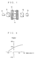
- the temperature dependency of the saturated magnetic field is shown in Fig. 8.
- Embodiment 1 The dependency of the Faraday rotating angle on the external magnetic field was measured by the procedure in Embodiment 1. With the Gd 0.65 Y 0.85 Bi 1.50 Fe 3.85 Ga 1.15 O12 single crystal obtained in this embodiment, the maximum value of the inverted magnetic field was 127 (Oe) within a temperature range of - 20 °C to 60 °. The magnetic compensation temperature was - 32 °C.
- Embodiment 1 The dependency of the Faraday rotating angle on the external magnetic field was measured by the procedure in Embodiment 1. With the Gd 1.17 Y 0.67 Bi 1.16 Fe 4.24 Ga 0.76 O12 single crystal obtained in this embodiment, the maximum value of the saturated magnetic field was 146 (Oe) in a temperature range of - 20 °C to 60 °C. The magnetic compensation temperature was - 40 °C.
- a platinum crucible having a capacity of 1000 ml lead oxide (PbO, 4N) of 1660g, bismuth oxide (Bi2O3, 4N) of 1160g, ferric oxide (Fe2O3, 4N) of 175g, boron oxide (B2O3, 5N) of 74.0g, gadolinium oxide (Gd2O3, 3N) of 10.3g , yttrium oxide (Y2O3, 3N) of 6.4g, gallium oxide (Ga2O3, 3N) of 35.0g and aluminum oxide (Al2O3, 3N) of 4.0g have been prepared. It was set at a predetermined position of a precise longitudinal tubular electric furnace. These compounds were heated and molten at 1000 °C, and sufficiently stirred to be mixed uniformly. Then, the melt thus obtained was cooled to 773 °C to grow a bismuth-substituted rare earth iron garnet single crystal.
- Embodiment 1 The dependency of the Faraday rotating angle on the external magnetic field was measured by the procedure in Embodiment 1. With the Gd 0.85 Y 0.86 Bi 1.29 Fe 4.00 Ga 0.76 Al 0.24 O12 single crystal obtained in this embodiment, the maximum value of the saturated magnetic field was 135 (Oe) in a temperature range of - 20 °C to 60 °C. The magnetic compensation temperature was - 36 °C.
- a platinum crucible having a capacity of 1000 ml lead oxide (PbO, 4N) of 1660g, bismuth oxide (Bi2O3, 4N) of 1160g, ferric oxide (Fe2O3, 4N) of 175g, boron oxide (B2O3, 5N) of 74.0g, gadolinium oxide (Gd2O3, 3N) of 10.3g , ytterbium oxide (Yb2O3, 3N) of 10.9g and gallium oxide (Ga2O3, 3N) of 28.0g have been prepared. It was set at a predetermined position of a precise longitudinal tubular electric furnace. These compounds were heated and molten at 1000 °C, and sufficiently stirred to be mixed uniformly. Then, the melt thus obtained was cooled to 755 °C to grow a bismuth-substituted rare earth iron garnet single crystal.
- Embodiment 1 The dependency of the Faraday rotating angle on the external magnetic field was measured by the procedure in Embodiment 1. With the Gd 0.76 Yb 0.71 Bi 1.53 Fe 4.20 Ga 0.80 O12 single crystal obtained in this embodiment, the maximum value of the saturated magnetic field was 142 (Oe) in a temperature range of - 20 °C to 60 °C. The magnetic compensation temperature was - 40 °C or lower.
- Embodiment 1 The dependency of the Faraday rotating angle on the external magnetic field was measured by the procedure in Embodiment 1. With the Gd 0.74 Lu 0.71 Bi 1.55 Fe 4.22 Ga 0.78 O12 single crystal obtained in this embodiment, the maximum value of the saturated magnetic field was 153 (Oe) in a temperature range of - 20 °C to 60 °C. The magnetic compensation temperature was - 40 °C or lower.
- a platinum crucible having a capacity of 1000 ml lead oxide (PbO, 4N) of 1660g, bismuth oxide (Bi2O3, 4N) of 1160g, ferric oxide (Fe2O3, 4N) of 175g, boron oxide (B2O3, 5N) of 74g, gadolinium oxide (Gd2O3, 3N) of 10.3g , yttrium oxide (Y2O3, 3N) of 3.2g, ytterbium oxide (Yb2O3, 3N) of 5.4g and gallium oxide (Ga2O3, 3N) of 39.0g have been prepared. It was set at a predetermined position of a precise longitudinal tubular electric furnace. These compounds were heated and molten at 1000 °C, and sufficiently stirred to be mixed uniformly. Then, the melt thus obtained was cooled to 766 °C to grow a bismuth-substituted rare earth iron garnet single crystal.
- Embodiment 1 The dependency of the Faraday rotating angle on the external magnetic field was measured by the procedure in Embodiment 1. With the Gd 0.72 Y 0.44 Yb 0.39 Bi 1.45 Fe 3.98 Ga 1.02 O12 single crystal obtained in this embodiment, the maximum value of the saturated magnetic field was 131 (Oe) in a temperature range of - 20 °C to 60 °C. The magnetic compensation was - 40 °C.
- a platinum crucible having a capacity of 1000 ml lead oxide (PbO, 4N) of 1660g, bismuth oxide (Bi2O3, 4N) of 1160g, ferric oxide (Fe2O3, 4N) of 175g, boron oxide (B2O3, 5N) of 74.0g, gadolinium oxide (Gd2O3, 3N) of 15.0g , yttrium oxide (Y2O3, 3N) of 4.3g, and gallium oxide (Ga2O3, 3N) of 39.0g have been prepared. It was set at a predetermined position of a precise longitudinal tubular electric furnace. These compounds were heated and molten at 1000 °C, and sufficiently stirred to be mixed uniformly. Then, the melt thus obtained was cooled to 770 °C to grow a bismuth-substituted rare earth iron garnet single crystal.
- the magnetic compensation temperature of the Gd 1.22 Y 0.58 Bi 1.20 Fe 3.99 Ga 1.01 O12 single crystal thus obtained was - 24 °C.
- a platinum crucible having a capacity of 1000 ml lead oxide (PbO, 4N) of 1660g, bismuth oxide (Bi2O3, 4N) of 1160g, ferric oxide (Fe2O3, 4N) of 175g, boron oxide (B2O3, 5N) of 74.0g, gadolinium oxide (Gd2O3, 3N) of 10.3g , yttrium oxide (Y2O3, 3N) of 8.3g, and gallium oxide (Ga2O3, 3N) of 39.0g have been prepared. It was set at a predetermined position of a precise longitudinal tubular electric furnace. These compounds were heated and molten at 1000 °C, and sufficiently stirred to be mixed uniformly. Then, the melt thus obtained was cooled to 768 °C to grow a bismuth-substituted rare earth iron garnet single crystal.
- the Gd 0.64 Y 0.93 Bi 1.43 Fe 3.95 Ga 1.05 O12 single crystal thus obtained has the maximum value of the inverted magnetic field of 172 (Oe) in the temperature range of - 20 °C to 60 °C.
- a platinum crucible having a capacity of 1000 ml lead oxide (PbO, 4N) of 1660g, bismuth oxide (Bi2O3, 4N) of 1160g, ferric oxide (Fe2O3, 4N) of 175g, boron oxide (B2O3, 5N) of 74.0g, gadolinium oxide (Gd2O3, 3N) of 10.3g , yttrium oxide (Y2O3, 3N) of 6.4g, and gallium oxide (Ga2O3, 3N) of 23.0g have been prepared. It was set at a predetermined position of a precise longitudinal tubular electric furnace. These compounds were heated and molten at 1000 °C, and sufficiently stirred to be mixed uniformly. Then, the melt thus obtained was cooled to 773 °C to grow a bismuth-substituted rare earth iron garnet single crystal.
- the Gd 0.85 Y 0.89 Bi 1.26 Fe 4.34 Ga 0.66 O12 single crystal thus obtained has the maximum value of the inverted magnetic field of 179 (Oe) in the temperature range of - 20 °C to 60 °C.
- a platinum crucible having a capacity of 1000 ml lead oxide (PbO, 4N) of 1660g, bismuth oxide (Bi2O3, 4N) of 1160g, ferric oxide (Fe2O3, 4N) of 175g, boron oxide (B2O3, 5N) of 74.0g, gadolinium oxide (Gd2O3, 3N) of 10.3g , yttrium oxide (Y2O3, 3N) of 6.4g, and gallium oxide (Ga2O3, 3N) of 50.0g have been prepared. It was set at a predetermined position of a precise longitudinal tubular electric furnace. These compounds were heated and molten at 1000 °C, and sufficiently stirred to be mixed uniformly. Then, the melt thus obtained was cooled to 759 °C to grow a bismuth-substituted rare earth iron garnet single crystal.
- the Gd 0.79 Y 0.78 Bi 1.43 Fe 3.71 Ga 1.29 O12 single crystal thus obtained has the maximum value of the inverted magnetic field of 185 (Oe) in the temperature range of - 20 °C to 60 °C.
- the Gd 0.85 Y 0.88 Bi 1.27 Fe 4.11 Ga 0.64 Al 0.24 O12 single crystal thus obtained has the maximum value of the inverted magnetic field of 177 (Oe) in the temperature range of - 20 °C to 60 °C.
- a platinum crucible having a capacity of 1000 ml lead oxide (PbO, 4N) of 1660g, bismuth oxide (Bi2O3, 4N) of 1160g, ferric oxide (Fe2O3, 4N) of 175g, boron oxide (B2O3, 5N) of 74.0g, gadolinium oxide (Gd2O3, 3N) of 10.3g , yttrium oxide (Y2O3, 3N) of 10.3g, holmium oxide (Ho2O3, 3N) of 8.4g and gallium oxide (Ga2O3, 3N) of 39g have been prepared. It was set at a predetermined position of a precise longitudinal tubular electric furnace. These compounds were heated and molten at 1000 °C, and sufficiently stirred to be mixed uniformly. Then, the melt thus obtained was cooled to 756 °C to grow a bismuth-substituted rare earth iron garnet single crystal.
- the Gd 0.97 H 0.75 Bi 1.28 Fe 3.98 Ga 1,02 O12 single crystal thus obtained has the maximum value of the inverted magnetic field of 183 (Oe) in the temperature range of - 20 °C to 60 °C.
Landscapes
- Chemical & Material Sciences (AREA)
- Engineering & Computer Science (AREA)
- Materials Engineering (AREA)
- Crystallography & Structural Chemistry (AREA)
- Metallurgy (AREA)
- Organic Chemistry (AREA)
- Inorganic Chemistry (AREA)
- Physics & Mathematics (AREA)
- Electromagnetism (AREA)
- Power Engineering (AREA)
- Crystals, And After-Treatments Of Crystals (AREA)
Applications Claiming Priority (2)
| Application Number | Priority Date | Filing Date | Title |
|---|---|---|---|
| JP108420/94 | 1994-05-23 | ||
| JP10842094A JP3458865B2 (ja) | 1994-05-23 | 1994-05-23 | 低飽和磁界ビスマス置換希土類鉄ガーネット単結晶、および、その用途 |
Publications (1)
| Publication Number | Publication Date |
|---|---|
| EP0684325A1 true EP0684325A1 (fr) | 1995-11-29 |
Family
ID=14484320
Family Applications (1)
| Application Number | Title | Priority Date | Filing Date |
|---|---|---|---|
| EP95107701A Withdrawn EP0684325A1 (fr) | 1994-05-23 | 1995-05-19 | Monocristal d'un grenat du type de fer-terre rare substitué par le bismuth à faible saturation de champ magnétique et son application |
Country Status (3)
| Country | Link |
|---|---|
| US (1) | US5512193A (fr) |
| EP (1) | EP0684325A1 (fr) |
| JP (1) | JP3458865B2 (fr) |
Families Citing this family (9)
| Publication number | Priority date | Publication date | Assignee | Title |
|---|---|---|---|---|
| US5566017A (en) * | 1994-08-04 | 1996-10-15 | Fdk Corporation | Material for magneto-optical element and faraday rotator using the same |
| JP3193945B2 (ja) * | 1995-03-17 | 2001-07-30 | 松下電器産業株式会社 | 磁気光学素子及び光磁界センサ |
| JP3624918B2 (ja) * | 1995-06-16 | 2005-03-02 | 三菱瓦斯化学株式会社 | 短波長用ビスマス置換希土類鉄ガーネット単結晶の製造法 |
| US5627924A (en) * | 1996-01-18 | 1997-05-06 | Lucent Technologies Inc. | Article comprising a non-mechanical optical fiber switch |
| EP1125333A4 (fr) * | 1998-10-01 | 2002-01-02 | Univ Arizona State | Commutation magnetique des durees de vie de separation de charges dans des centres de reaction photosynthetique artificielle |
| JP2002528707A (ja) | 1998-10-21 | 2002-09-03 | ジー. ダンカン,ポール | 希土類鉄ガーネットを用いて光の波面の偏光回転を光学的に測定するための装置および方法 |
| JP3649935B2 (ja) * | 1999-03-15 | 2005-05-18 | Tdk株式会社 | 磁性ガーネット材料およびそれを用いたファラデー回転子 |
| US20090053558A1 (en) * | 2004-11-15 | 2009-02-26 | Integrated Phototonics, Inc. | Article comprising a thick garnet film with negative growth-induced anisotropy |
| JP5528827B2 (ja) * | 2010-01-25 | 2014-06-25 | 信越化学工業株式会社 | 光アイソレータ |
Citations (6)
| Publication number | Priority date | Publication date | Assignee | Title |
|---|---|---|---|---|
| JPS61468A (ja) * | 1984-06-14 | 1986-01-06 | Fuji Electric Co Ltd | 電気集塵器の間欠荷電制御方式 |
| JPS6120926A (ja) | 1984-07-09 | 1986-01-29 | Nec Corp | 磁気光学素子材料 |
| JPS63301918A (ja) | 1987-06-01 | 1988-12-08 | Nippon Telegr & Teleph Corp <Ntt> | ファイバ可動型光スイッチ |
| EP0368483A2 (fr) * | 1988-11-11 | 1990-05-16 | Fuji Electrochemical Co.Ltd. | Matériau magnéto-optique |
| EP0510621A2 (fr) * | 1991-04-25 | 1992-10-28 | Matsushita Electric Industrial Co., Ltd. | Elément magnéto-optique et dispositif de mesure des champs magnétiques |
| JPH05249523A (ja) | 1991-12-20 | 1993-09-28 | Akzo Nv | 光学的に非線形な媒体中に周波数倍加構造を作る方法 |
-
1994
- 1994-05-23 JP JP10842094A patent/JP3458865B2/ja not_active Expired - Fee Related
-
1995
- 1995-05-19 EP EP95107701A patent/EP0684325A1/fr not_active Withdrawn
- 1995-05-23 US US08/447,592 patent/US5512193A/en not_active Expired - Fee Related
Patent Citations (6)
| Publication number | Priority date | Publication date | Assignee | Title |
|---|---|---|---|---|
| JPS61468A (ja) * | 1984-06-14 | 1986-01-06 | Fuji Electric Co Ltd | 電気集塵器の間欠荷電制御方式 |
| JPS6120926A (ja) | 1984-07-09 | 1986-01-29 | Nec Corp | 磁気光学素子材料 |
| JPS63301918A (ja) | 1987-06-01 | 1988-12-08 | Nippon Telegr & Teleph Corp <Ntt> | ファイバ可動型光スイッチ |
| EP0368483A2 (fr) * | 1988-11-11 | 1990-05-16 | Fuji Electrochemical Co.Ltd. | Matériau magnéto-optique |
| EP0510621A2 (fr) * | 1991-04-25 | 1992-10-28 | Matsushita Electric Industrial Co., Ltd. | Elément magnéto-optique et dispositif de mesure des champs magnétiques |
| JPH05249523A (ja) | 1991-12-20 | 1993-09-28 | Akzo Nv | 光学的に非線形な媒体中に周波数倍加構造を作る方法 |
Non-Patent Citations (2)
| Title |
|---|
| HIBIYA ET AL: "Growth and Magneto-optic properties of liquid phase epitaxial Bi-substituted garnet films for optical isolator", NEC RESEARCH AND DEVELOPMENT, no. 1, January 1986 (1986-01-01), pages 1 - 8 * |
| PATENT ABSTRACTS OF JAPAN vol. 10, no. 169 (P - 468) 14 June 1986 (1986-06-14) * |
Also Published As
| Publication number | Publication date |
|---|---|
| JP3458865B2 (ja) | 2003-10-20 |
| US5512193A (en) | 1996-04-30 |
| JPH07315995A (ja) | 1995-12-05 |
Similar Documents
| Publication | Publication Date | Title |
|---|---|---|
| US5408565A (en) | Thin-film magneto-optic polarization rotator | |
| US7517406B2 (en) | Magnetic garnet material, faraday rotator, optical device, bismuth-substituted rare earth-iron-garnet single-crystal film and method for producing the same and crucible for producing the same | |
| EP0208476A2 (fr) | Capteur de champ magnétique ayant un élément magnéto-optique | |
| Bahuguna et al. | Magneto-optic-based fiber switch for optical communications | |
| US5512193A (en) | Low saturated magnetic field bismuth-substituted rare earth iron garnet single crystal and its use | |
| EP0811851B1 (fr) | Rotateur de Faraday avec hystérésis rectangulaire | |
| US5521741A (en) | Polarization plane switch and optical switching device using the same | |
| US5535046A (en) | Faraday rotator | |
| JP3198053B2 (ja) | 低磁気モーメントを有する磁気光学材からなる製品 | |
| US5608570A (en) | Article comprising a magneto-optic material having low magnetic moment | |
| JPH07206593A (ja) | 光アイソレータ用ファラデー回転子 | |
| JP3237031B2 (ja) | ビスマス置換希土類鉄ガーネット単結晶膜,光アイソレータ及び磁気光学スイッチ | |
| Tsushima et al. | Research activities on magneto-optical devices in Japan | |
| US6673146B2 (en) | Method of manufacturing a magnet-free faraday rotator | |
| Levy et al. | Permanent magnet film magneto‐optic waveguide isolator | |
| EP0785454A1 (fr) | Rotateur de Faraday pour rapteurs magnéto-optiques | |
| US6770223B1 (en) | Article comprising a faraday rotator that does not require a bias magnet | |
| Nakano et al. | Magneto-optical properties of YIG single crystal by TSFZ method | |
| Fratello et al. | Growth and characterization of magnetooptic garnet films with planar uniaxial anisotropy | |
| JPH1031112A (ja) | 角型ヒステリシスを示すファラデー回転子 | |
| JP3917859B2 (ja) | ファラデー回転子 | |
| Koshizuka et al. | Growth-induced birefringence in LPE-grown iron garnet films | |
| JPH07104224A (ja) | 非相反光デバイス | |
| JPH04118623A (ja) | 磁気光学材料、その製造法およびそれを用いた光素子 | |
| JPH0826900A (ja) | 希土類鉄ガーネット単結晶膜の処理方法 |
Legal Events
| Date | Code | Title | Description |
|---|---|---|---|
| PUAI | Public reference made under article 153(3) epc to a published international application that has entered the european phase |
Free format text: ORIGINAL CODE: 0009012 |
|
| AK | Designated contracting states |
Kind code of ref document: A1 Designated state(s): DE FR GB |
|
| 17P | Request for examination filed |
Effective date: 19960506 |
|
| STAA | Information on the status of an ep patent application or granted ep patent |
Free format text: STATUS: THE APPLICATION HAS BEEN WITHDRAWN |
|
| 18W | Application withdrawn |
Withdrawal date: 19980318 |