EP0684340A1 - Herstellungsverfahren für aus einer zusammengesetzten Platte ausgeschnittene Belagselemente und Belagselement - Google Patents
Herstellungsverfahren für aus einer zusammengesetzten Platte ausgeschnittene Belagselemente und Belagselement Download PDFInfo
- Publication number
- EP0684340A1 EP0684340A1 EP95201377A EP95201377A EP0684340A1 EP 0684340 A1 EP0684340 A1 EP 0684340A1 EP 95201377 A EP95201377 A EP 95201377A EP 95201377 A EP95201377 A EP 95201377A EP 0684340 A1 EP0684340 A1 EP 0684340A1
- Authority
- EP
- European Patent Office
- Prior art keywords
- facing
- cutting
- layer
- composite
- underlayment
- Prior art date
- Legal status (The legal status is an assumption and is not a legal conclusion. Google has not performed a legal analysis and makes no representation as to the accuracy of the status listed.)
- Granted
Links
- 238000000034 method Methods 0.000 title claims abstract description 27
- 238000005520 cutting process Methods 0.000 title claims description 58
- 238000004519 manufacturing process Methods 0.000 title claims description 43
- 239000002131 composite material Substances 0.000 claims abstract description 70
- 239000000463 material Substances 0.000 claims abstract description 26
- 238000000465 moulding Methods 0.000 claims abstract description 11
- 239000011248 coating agent Substances 0.000 claims description 21
- 238000000576 coating method Methods 0.000 claims description 21
- 238000009434 installation Methods 0.000 claims description 17
- 238000009415 formwork Methods 0.000 claims description 14
- 239000007787 solid Substances 0.000 claims description 13
- XLYOFNOQVPJJNP-UHFFFAOYSA-N water Substances O XLYOFNOQVPJJNP-UHFFFAOYSA-N 0.000 claims description 12
- 238000004873 anchoring Methods 0.000 claims description 10
- 230000002093 peripheral effect Effects 0.000 claims description 5
- 239000000853 adhesive Substances 0.000 claims description 4
- 230000001070 adhesive effect Effects 0.000 claims description 4
- 238000001035 drying Methods 0.000 claims description 4
- 239000011230 binding agent Substances 0.000 claims description 3
- 239000010438 granite Substances 0.000 abstract description 4
- 238000010276 construction Methods 0.000 abstract 1
- 239000010410 layer Substances 0.000 description 49
- 239000004575 stone Substances 0.000 description 6
- 229910003460 diamond Inorganic materials 0.000 description 3
- 239000010432 diamond Substances 0.000 description 3
- 239000011343 solid material Substances 0.000 description 3
- 239000012790 adhesive layer Substances 0.000 description 2
- 230000001788 irregular Effects 0.000 description 2
- 239000004579 marble Substances 0.000 description 2
- 239000002184 metal Substances 0.000 description 2
- 239000004570 mortar (masonry) Substances 0.000 description 2
- 229920002994 synthetic fiber Polymers 0.000 description 2
- 239000002023 wood Substances 0.000 description 2
- 239000004819 Drying adhesive Substances 0.000 description 1
- 241000272186 Falco columbarius Species 0.000 description 1
- GJAARPKBDFKHFS-UHFFFAOYSA-N Gerin Natural products COC(=O)C(=C)C1CC2C(=C)C(=O)C=CC2(C)CC1OC(=O)C GJAARPKBDFKHFS-UHFFFAOYSA-N 0.000 description 1
- 239000000654 additive Substances 0.000 description 1
- 239000012237 artificial material Substances 0.000 description 1
- 230000005540 biological transmission Effects 0.000 description 1
- 210000004027 cell Anatomy 0.000 description 1
- 239000000919 ceramic Substances 0.000 description 1
- 238000005253 cladding Methods 0.000 description 1
- 230000006835 compression Effects 0.000 description 1
- 238000007906 compression Methods 0.000 description 1
- 230000003750 conditioning effect Effects 0.000 description 1
- 210000003298 dental enamel Anatomy 0.000 description 1
- 238000006073 displacement reaction Methods 0.000 description 1
- 239000000835 fiber Substances 0.000 description 1
- 230000006870 function Effects 0.000 description 1
- 238000003698 laser cutting Methods 0.000 description 1
- 239000005445 natural material Substances 0.000 description 1
- 230000003287 optical effect Effects 0.000 description 1
- 238000004806 packaging method and process Methods 0.000 description 1
- 238000009417 prefabrication Methods 0.000 description 1
- 230000003014 reinforcing effect Effects 0.000 description 1
- 238000005096 rolling process Methods 0.000 description 1
- 238000009416 shuttering Methods 0.000 description 1
- 238000010025 steaming Methods 0.000 description 1
Images



Classifications
-
- B—PERFORMING OPERATIONS; TRANSPORTING
- B28—WORKING CEMENT, CLAY, OR STONE
- B28B—SHAPING CLAY OR OTHER CERAMIC COMPOSITIONS; SHAPING SLAG; SHAPING MIXTURES CONTAINING CEMENTITIOUS MATERIAL, e.g. PLASTER
- B28B19/00—Machines or methods for applying the material to surfaces to form a permanent layer thereon
- B28B19/0053—Machines or methods for applying the material to surfaces to form a permanent layer thereon to tiles, bricks or the like
-
- B—PERFORMING OPERATIONS; TRANSPORTING
- B23—MACHINE TOOLS; METAL-WORKING NOT OTHERWISE PROVIDED FOR
- B23D—PLANING; SLOTTING; SHEARING; BROACHING; SAWING; FILING; SCRAPING; LIKE OPERATIONS FOR WORKING METAL BY REMOVING MATERIAL, NOT OTHERWISE PROVIDED FOR
- B23D59/00—Accessories specially designed for sawing machines or sawing devices
- B23D59/008—Accessories specially designed for sawing machines or sawing devices comprising computers
-
- B—PERFORMING OPERATIONS; TRANSPORTING
- B28—WORKING CEMENT, CLAY, OR STONE
- B28B—SHAPING CLAY OR OTHER CERAMIC COMPOSITIONS; SHAPING SLAG; SHAPING MIXTURES CONTAINING CEMENTITIOUS MATERIAL, e.g. PLASTER
- B28B11/00—Apparatus or processes for treating or working the shaped or preshaped articles
- B28B11/14—Apparatus or processes for treating or working the shaped or preshaped articles for dividing shaped articles by cutting
-
- B—PERFORMING OPERATIONS; TRANSPORTING
- B28—WORKING CEMENT, CLAY, OR STONE
- B28D—WORKING STONE OR STONE-LIKE MATERIALS
- B28D1/00—Working stone or stone-like materials, e.g. brick, concrete or glass, not provided for elsewhere; Machines, devices, tools therefor
- B28D1/02—Working stone or stone-like materials, e.g. brick, concrete or glass, not provided for elsewhere; Machines, devices, tools therefor by sawing
- B28D1/04—Working stone or stone-like materials, e.g. brick, concrete or glass, not provided for elsewhere; Machines, devices, tools therefor by sawing with circular or cylindrical saw-blades or saw-discs
- B28D1/043—Gantry type sawing machines
-
- E—FIXED CONSTRUCTIONS
- E01—CONSTRUCTION OF ROADS, RAILWAYS, OR BRIDGES
- E01C—CONSTRUCTION OF, OR SURFACES FOR, ROADS, SPORTS GROUNDS, OR THE LIKE; MACHINES OR AUXILIARY TOOLS FOR CONSTRUCTION OR REPAIR
- E01C5/00—Pavings made of prefabricated single units
- E01C5/22—Pavings made of prefabricated single units made of units composed of a mixture of materials covered by two or more of groups E01C5/008, E01C5/02 - E01C5/20 except embedded reinforcing materials
-
- E—FIXED CONSTRUCTIONS
- E01—CONSTRUCTION OF ROADS, RAILWAYS, OR BRIDGES
- E01C—CONSTRUCTION OF, OR SURFACES FOR, ROADS, SPORTS GROUNDS, OR THE LIKE; MACHINES OR AUXILIARY TOOLS FOR CONSTRUCTION OR REPAIR
- E01C2201/00—Paving elements
- E01C2201/04—Paving elements consisting of natural stones and a binder
Definitions
- the invention relates to a method of manufacturing composite covering elements comprising a facing layer made of rigid solid noble material associated with an underlayment of composite material suitable for being applied by molding and hardening after its use. , as well as a coating element thus obtained.
- Covering elements such as pavers or tiles are for example used for coating road surfaces such as sidewalks or streets, or the walls or floors of buildings. These elements can have various contours which can be square or rectangular or more complex. However, they must be particularly aesthetic, with mechanical characteristics suitable for their use, and inexpensive to manufacture and install.
- covering elements such as pavers made of solid material, for example granite.
- These coating elements have the disadvantage of a very high price linked to the price of the material used.
- the solid pavers generally produced by splitting have irregular shapes, which affects the aesthetics of the coating and increases the laying costs given the need to call in specialized labor.
- European patent application EP-A-0.176.471 describes a composite covering element formed by an outer layer of solid material such as stone bonded by a mortar on a concrete support layer.
- the concrete support is applied to the outer layer by hand or by an appropriate machine on the site before use.
- the saving made by the material is offset by the cost of labor and by the low productivity of the manufacturing process. Indeed, it is unrealistic to think that it is possible to mold on site each concrete support layer of each paver, then to individually paste the concrete support layer obtained on each external layer of stone previously cut to the appropriate dimensions .
- the invention therefore aims to remedy all of the above-mentioned drawbacks of the prior art.
- the invention aims to propose a method of manufacturing composite coating elements having the aesthetic appearance of a solid noble material, but the overall cost of manufacture and installation is of the same order as or slightly higher than that covering elements made entirely of concrete.
- the invention also aims to propose a manufacturing process by which the appearance and finish of the coating elements is of very good quality without however increasing the manufacturing cost.
- the invention also aims to propose a manufacturing process allowing the manufacture of composite coating elements whose nature and shape may vary, and whose price is at least substantially independent of the shape given to the coating elements.
- the invention aims to propose a manufacturing process allowing the prefabrication of the composite coating elements according to an industrial process in large quantities, but which nevertheless makes it possible to give the coating elements any shape which can be defined on demand and tailor-made according to each site.
- the invention also aims to propose a process for manufacturing composite coating elements with improved mechanical strength in compression and in shear economically.
- the invention also aims to provide a composite covering element having a good aesthetic appearance and whose cost and installation cost is low, that is to say of the same order of magnitude or slightly higher than that of elements made up entirely of concrete.
- the invention also aims to provide a such a composite coating element whose mechanical characteristics are improved, and in particular a coating element more particularly intended for the coating of road surfaces (sidewalks, streets ).
- the composite slab is cut in at least two distinct steps including a precut step during which a network of notches is produced from the free external face of the molded underlayment underlayment. pre-cutting of predetermined height in at least part of the thickness of the underlayment, so as to pre-cut the covering elements.
- the underlayment is associated with the facing plate by means of a bonding layer, the drying time of which is less than the curing time of the underlayment. And the pre-cutting step is carried out after the adhesive layer has dried.
- a bonding layer is used consisting of an adhesive comprising a hydraulic binder and water.
- the underlayment is associated with the facing plate by means of mechanical fixing means uniformly distributed on the surface between the facing plate and the facing underlayment, in particular in the form of anchor snaps rigidly associated - notably riveted - to the anchor plate before molding and the association of the underlayment.
- the invention also relates to a composite coating element obtained by a manufacturing process according to the invention.
- a composite covering element such as a paver, a tile, etc., comprising a facing layer made of rigid solid noble material associated with a facing under layer of material suitable for being molded. and hardening after its implementation, characterized in that its lateral faces and the sharp edges of the facing layer have the surface state and the appearance left by a cutting tool such as a saw, a jet of pressurized water or a laser.
- the invention further relates to a manufacturing method and a composite coating element comprising in combination all or part of the characteristics mentioned above or below.
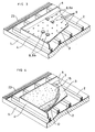
- FIG. 1 represents a rigid work table 1 on which battens 2 have been arranged parallel to one another.
- battens 2 On the battens 2, one or more facing plates 3 are placed, the dimensions of which in width and in length are greater than those of the composite covering elements to be manufactured.
- peripheral walls 4 of formwork extending all around each of the plates 3.
- the height of the formwork walls 4 around the periphery of each facing plate 3 is constant and is defined as a function of the desired height for the underlayment layer 12 subsequently molded in the mold formed by the facing plate 3 which acts as the formwork bottom, and the peripheral formwork 4.
- the table 1, the battens 2, the facing plate 3 and the formwork walls 4 are only partially shown for clarity.
- the working table 1 used can be a very long table, for example with a length of the order of 100 meters, and with a width of the order of 1 to 5 meters.
- a series of facing plates 3 made of solid noble material, precut, having a width of the order of 1 to 5 meters and a length of the order of 2 to 10 meters are then laid along this work table 1 on the battens 2.
- a formwork is produced using walls 4 around each plate 3.
- the facing plates 3 used can be made of a natural material such as natural stone, granite, marble, wood, etc. artificial material such as synthetic material, ceramic, enamel, etc.
- the thickness of the facing plate 3 used can vary, for example between 5 and 45 mm.
- facing plates 3 are used which come directly from a sawing step of a solid block of the material concerned. Indeed, it has been found that the surface condition resulting from sawing is sufficiently aesthetic in the majority of cases from the point of view of the appearance imparted to the external face 6 of the facing plate 3, but also allows '' Significantly improve the adhesion of the underlayment 12 and / or a bonding layer 7 applied to the internal face 5 of the facing plate 3. Alternatively, however, scarification by bush hammering may be carried out or flame the inner face 5 of the facing plate 3 intended to receive the underlayment 12 and / or the bonding layer.
- each facing plate 3 is arranged at least substantially horizontally on the work table 1 with its external face 6 free facing facing down.
- FIG 2 there is shown the subsequent step during which a bonding layer 7 is extended on the inner face 5 of the facing plate 3.
- This bonding layer 7 is made of a binder-forming material and / or adhesive whose drying time is less than the curing time of the subsequently applied underlayment.
- This bonding layer 7 can consist of an adhesive comprising a hydraulic binder and water, for example a slip layer.
- a slip layer 7 is used when the backing underlayment 12 applied subsequently consists of concrete.
- FIG. 3 an alternative embodiment is shown in which the underlay is associated facing 12 to the facing plate 3 by means of mechanical fixing means 8 uniformly distributed on the surface between the facing plate 3 and the underlayment facing 12 applied later.
- These fixing means 8 are formed by anchoring snaps 8a, 8b rigidly associated with the plate 3 before molding and the association of the underlayment 12 and so as to extend within the underlayment counter 12 when it is mounted on the plate 3.
- the anchoring snaps 8a, 8b are riveted in holes 9 formed in the facing plate 3 beforehand.
- Each anchoring snap 8a, 8b comprises a rivet 10, which can be a rivet to be struck or a rivet by deformation, and which is engaged in a bore 9 of the facing plate 3.
- This rivet 10 carries an anchoring plate 11 which projects from the facing plate 3 inside the subsequently applied underlayment layer 12.
- the plate 11a is for example a profile portion with a cross section in the form of a U and thus defines two parallel wings which extend perpendicular to the facing plate 3 to the inside the underlayment underlay 12.
- the plate 11b of the anchoring snap 8b can be formed of a hemispherical dome 11b riveted by its bottom, and which has at its portion furthest from the facing plate 3, a flange 13 which extends at least substantially parallel to the inner face 5 of this facing plate 3.
- a bonding layer 7 and mechanical fixing means 8 can be used in combination.
- This under-layer of facing 12 is for example formed from fresh concrete, poured directly inside the mold formed by the facing plate 3 and the walls 4 of formwork. According to the invention, this underlayment 12 is poured before the bonding layer 7 is hardened.
- the underlayment 12 is advantageously made of a concrete, for example a class B60 concrete or any other material - in particular a composite material - able to be used by molding and hardening after its use. This concrete is then vibrated and leveled.
- the outer upper face 15 of the underlayment layer 12 is then grooved, so as to have grooves 16 facilitating the subsequent installation of the composite elements ( Figures 11 and 13).
- the thickness of the backing sublayer 12 is greater than that of the facing plate 3 which is as small as possible taking into account the mechanical constraints and the imperatives of manufacturing and handling.
- the underlayment 12 can be made of reinforced, prestressed material, fiber concrete or incorporating various additives, material based on composite or non-composite synthetic material, loaded or not ... The material is chosen according to the properties mechanical sought and its cost.
- Each composite slab 14 thus produced is then cut perpendicular to its main plane, into a plurality of composite covering elements 17 ready to install.
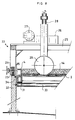
- FIG. 5 schematically represents the installation used to cut the composite slab 14 into elements 17. It is possible, for example, to use an installation and a method described in document EP-A-0.197.844 by replacing the tracing nozzle of this document with a cutting tool.
- a computer 18 the dimensions, shapes and arrangement of the composite elements 17, for example from a plane 19. From this computer 18 programmed in an appropriate manner and known per se by computer-aided drawing software or software package (for example AUTOCAD (registered trademark) and / or computer-aided production management type, a layout of the elements to be produced is established, and a removable mass memory is prepared such as a floppy disk 20 on which the data making it possible to trace are stored. and to carry out the cutting of each large composite slab 14 into elements 17.
- This floppy disk 20 is directly used by an automaton 21 equipped with a computer system and also programmed in a manner known per se to control the operation of a robot. cutting 22.
- the data stored on the removable memory 20 include in particular the manufacturing sheets of each coating element to manufacture, and the number of elements of the same shapes and dimensions. These data are formatted by the computer 18 on the memory 20 to be directly usable by the software of the automaton 21.
- the automaton 21 and its software are for example of the type of those marketed by the company MERLIN GERIN (Meylan, France ).
- the software of the automaton 21 makes it possible to optimize the operations and displacements of the cutting tool while minimizing the falls.
- This cutting robot 22 is for example formed of a carriage which rolls longitudinally on longitudinal racks 23 extending on each side of the table 1. The carriage then carries 24 toothed wheels motorized by a motorization device carried by the carriage , known per se and not shown.
- the robot 22 can move under the control of the automaton 21 along the work table 1.
- the robot 22 can also be located by an optical tracking device known per se.
- the robot carriage 22 comprises a transverse beam 25 on which a tool holder 26 can move in transverse translation under the control of the automaton 21.
- the transverse beam 25 carries for example a rack rail on which toothed wheels of the tool holder 26 come to roll. These toothed wheels are motorized by a motor 27 controlled by the automaton 21.
- the tool holder 26 comprises an arm 28 extending vertically downwards and carrying the cutting tool which is, in the example shown, a saw circular diamond rotary 29 driven in rotation by a suitable transmission through the arm 28 by a motor.
- the arm 28 also has its relative position relative to the tool holder 26 which can be adjusted under the control of the automaton 21 or manually.
- the arm 28 can at least be rotated, in particular by 90 ° around its vertical axis so as to be able to place the saw 29 either in the longitudinal direction of the table 1 parallel to the racks 23 on which the carriage rolls, or perpendicular to this direction, that is to say transversely to the table 1, that is to say in any intermediate position.
- the composite slab 14 is shown, and the formwork walls 4 have been removed before cutting.
- the cutting tool used is a pressurized water jet or a laser
- the shuttering walls 4 can be left in place during the cutting step, in particular during the pre-cutting step described below.
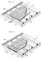
- the composite slab 14 is cut in at least two distinct steps, including a precut step which is shown in FIG. 6.
- a precut step which is shown in FIG. 6.
- the free external face 15 of the sub is produced molded backing layer 12, a network of continuous pre-cut notches 30 of predetermined height in at least part of the thickness of the backing underlay 12, so as to pre-cut the covering elements 17.
- the network of precut notches 30 is in the form of a grid.
- This pre-cutting step is carried out before the end of the hardening of the underlayment layer 12, but preferably after the hardening of the bonding layer 7.
- Pre-cut notches 30 are made whose height is less than the thickness of the underlayment 12 so as not to start the bonding layer 7, but greater than half of this thickness. For example, a thickness of 0.3 to 2 cm is left between the bottom of the notches 30 and the bonding layer 7.
- the curing of the backing underlay 12 is completed, then performs a final cutting step during which the covering elements 17 are cut and separated by cutting the residual thickness of the composite slab 14 left between the bottom of the pre-cut notches 30 and the free external face 6 of the facing plate 3. In the final cutting step shown in FIG. 7 and carried out on the same installation (FIG.
- a cutting tool 29 is engaged in the pre-cutting notches 30 which serve as a guide for the tool 29 during the final cutting step.
- the pre-cutting stage is carried out with the same tools and the same installation as the final cutting stage. However, between these two stages, it is possible to handle the composite slabs 14, for example to accelerate the hardening of the underlayment underlay 12 by steaming or the like.
- the composite slabs 14 are rigidly fixed to the work table 12 on which the cutting robot 22 moves, both before the pre-cutting step and before the final cutting step. And each composite slab 14 is fixed to the table 1 in a precise and identified predetermined position.
- FIG. 9 represents an exemplary embodiment of the precut notches 30, that is to say a detail of the section of the composite slab 14 represented in FIG. 6.
- the precut in the not yet hardened underlayment 12 is an easy step to perform with a standard tool, such as a diamond saw.
- the pre-cutting step and the final cutting step can also be carried out by cutting with a pressurized water jet.
- a low power water jet can be used (for example under a pressure of less than 100 bars).
- a cutting laser can also be used.
- the precut step can be carried out quickly if a fast-drying adhesive layer 7 and / or mechanical fixing means 8 are used.
- the same work table 1 was used to manufacture the composite slabs 14, then to cut them into elements 17.
- the work table 1 on which the slab is manufactured composite 14 of large dimensions forms the support for a cutting installation, so that at least one cutting step can be carried out without handling the composite slab 14 after its manufacture. It is thus possible to manufacture a large number of elements 17 without specific handling of the slabs 14 during the process.
- each composite slab 14 is prepared on a metal frame 31 carrying composite wood panels or battens 2 and a removable metal peripheral formwork 4.
- These frames 31 are removably mounted on a frame 32 of the cutting installation, thanks to transverse rollers 33 mounted on the frame 32.
- the frame 32 also carries the longitudinal racks 23 on which the cutting robot 22 rolls.
- the frame 32 also defines longitudinal support shoulders 34 receiving a longitudinal angle 35 of the chassis 31 carrying the slab 14.
- Each frame 31 can therefore be placed on the frame 32 by rolling it on the rollers 33, and is then rigidly fixed relative to the frame 32 by any suitable means (bolts, flanges, etc.).
- bolts, flanges, etc. any suitable means
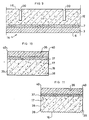
- Figures 10 to 13 show examples of composite elements 17 according to the invention obtained by a method according to the invention.
- These composite elements 17 can be used as vertical or horizontal covering elements, load-bearing or not. It is thus possible to manufacture paving stones, road slabs, cladding slabs, tiles, etc.
- These composite elements 17 are planar.
- the method and the invention are also applicable for manufacturing non-planar elements such as curbs, stair nosings, elements of urban furniture, load-bearing elements such as rubble stones ... '' use one or more appropriately shaped facing plates 3.
- each composite slab 14 can be cut into elements 17 of any geometric shape, in particular if a water jet or laser cutting is used. The most complex forms can be considered. And it is not necessary to make a formwork or a mold for each covering element 17 to be manufactured.
- the element 17 therefore comprises a facing layer 36 formed of a portion of the facing plate 3 initially used to prepare a slab 14.
- This facing layer 36 is made of rigid solid noble material and therefore has a decorative aesthetic external face.
- the facing layer 36 is rigidly associated with a facing underlay 38 which is a portion of the facing underlay 12 formed on the facing plate 3 by the method according to the invention.
- the underlayment 38 is therefore made of a composite material capable of being processed by molding and hardening after it has been used.
- the facing layer 36 is rigidly associated with the facing sublayer 38 by means of a bonding layer 37 which is a portion of the bonding layer 7 or by means of the mechanical fixing means 8.
- the composite element 17 has its lateral faces 39 and the sharp edges 40 of the facing layer 36 at the junction of these lateral faces 39 which have a surface state and an appearance left by a cutting tool such as a saw, a pressurized water jet or a laser. These lateral faces 39 and these edges 40 are therefore perfectly regular and smooth and therefore have an improved appearance.
- FIGS. 10 and 11 show the variant in which the composite element comprises a bonding layer 37 which is therefore a portion of the bonding layer 7 of a slab 14.
- the inner face of the facing layer 36 is grooved or scarified to facilitate the connection between this facing layer 36 and the adhesive layer 37.
- FIGS. 12 and 13 there is shown the variant in which anchor snaps 8a, 8b are used, fixed anchored - notably riveted - in the facing layer 36 and extending within the facing underlay 38.
- FIGS. 11 and 13 also shown grooves 16 formed on the lower external surface of the underlayment 38 and which facilitate the installation of the element 17.
- the invention can be the subject of numerous variants, and in particular it is possible to combine the various variants described above.
Landscapes
- Engineering & Computer Science (AREA)
- Mechanical Engineering (AREA)
- Structural Engineering (AREA)
- Chemical & Material Sciences (AREA)
- Ceramic Engineering (AREA)
- Civil Engineering (AREA)
- Architecture (AREA)
- Mining & Mineral Resources (AREA)
- Processing Of Stones Or Stones Resemblance Materials (AREA)
- Devices For Post-Treatments, Processing, Supply, Discharge, And Other Processes (AREA)
- Finishing Walls (AREA)
- Laminated Bodies (AREA)
- Shearing Machines (AREA)
- Fixed Capacitors And Capacitor Manufacturing Machines (AREA)
- Manufacture Of Switches (AREA)
Applications Claiming Priority (2)
| Application Number | Priority Date | Filing Date | Title |
|---|---|---|---|
| FR9406718 | 1994-05-27 | ||
| FR9406718A FR2720416B1 (fr) | 1994-05-27 | 1994-05-27 | Procédé de fabrication d'éléments de revêtement découpés dans une dalle composite et élément de revêtement obtenu. |
Publications (2)
| Publication Number | Publication Date |
|---|---|
| EP0684340A1 true EP0684340A1 (de) | 1995-11-29 |
| EP0684340B1 EP0684340B1 (de) | 2000-01-26 |
Family
ID=9463777
Family Applications (1)
| Application Number | Title | Priority Date | Filing Date |
|---|---|---|---|
| EP95201377A Expired - Lifetime EP0684340B1 (de) | 1994-05-27 | 1995-05-24 | Herstellungsverfahren für aus einer zusammengesetzten Platte ausgeschnittene Belagselemente und Belagselement |
Country Status (4)
| Country | Link |
|---|---|
| EP (1) | EP0684340B1 (de) |
| AT (1) | ATE189283T1 (de) |
| DE (1) | DE69514713D1 (de) |
| FR (1) | FR2720416B1 (de) |
Cited By (10)
| Publication number | Priority date | Publication date | Assignee | Title |
|---|---|---|---|---|
| WO1998024976A1 (fr) * | 1995-05-11 | 1998-06-11 | Jean Brignoli | Materiau composite - pierre naturelle, granit ou marbre et beton |
| EP1136215A3 (de) * | 1999-05-10 | 2003-01-02 | SACMI COOPERATIVA MECCANICI IMOLA S.c.r.l. | Anpassungsfähiges Verfahren zum Herstellen keramischer Fliesen verschiedener Grösse, Vorrichtung zum Durchführen des Verfahrens und so hergestellte Fliesen |
| EP1354680A1 (de) * | 2002-04-18 | 2003-10-22 | Viki Ceramiche Artistiche -S.R.L. | Verfahren und Gerät zum Schneiden von plattenförmigem Gegenständen |
| WO2006043294A1 (en) * | 2004-10-20 | 2006-04-27 | Dario Toncelli | Combined apparatus for machining of articles, in particular in form of slabs |
| WO2007036845A1 (en) * | 2005-09-27 | 2007-04-05 | Maema S.R.L. | Machine tool for surface processing of products of stone material or the like |
| US7240415B2 (en) | 2004-06-23 | 2007-07-10 | Dario Toncelli | Machine for processing material in the form of slabs, in particular natural stone material, ceramic material and conglomerate |
| US7771249B2 (en) | 2007-03-30 | 2010-08-10 | Park Industries, Inc. | Corner saw |
| CN105935807A (zh) * | 2016-06-24 | 2016-09-14 | 无锡欧诺锁业有限公司 | 一种使用方便的五金件切割机 |
| US9886019B2 (en) | 2013-04-10 | 2018-02-06 | Dario Toncelli | Apparatus for cutting slab material |
| DE102020134667A1 (de) | 2020-12-22 | 2022-06-23 | Godelmann Gmbh & Co. Kg | Verfahren und Vorrichtung zur Herstellung von Bodenbelagselementen aus Beton sowie Bodenbelagselement aus Beton |
Families Citing this family (3)
| Publication number | Priority date | Publication date | Assignee | Title |
|---|---|---|---|---|
| FR2751004B1 (fr) * | 1996-07-12 | 1998-11-06 | Communaute Urbaine De Lyon | Procede d'assemblage de dalles pour constituer un revetement de sol et dalles pour la mise en oeure du procede |
| US10201914B2 (en) | 2015-01-20 | 2019-02-12 | Park Industries, Inc. | Material loading apparatus |
| CN120307442B (zh) * | 2025-05-21 | 2025-12-02 | 济南四建(集团)有限责任公司 | 应用于节能建筑砌块制造生产的去底皮设备及其方法 |
Citations (11)
| Publication number | Priority date | Publication date | Assignee | Title |
|---|---|---|---|---|
| US1925460A (en) * | 1930-09-13 | 1933-09-05 | William O Luly | Surfacing material and method of forming same |
| DE1890769U (de) * | 1964-02-13 | 1964-04-09 | Erwin Wrede | Fussbodenplatte. |
| FR1524275A (fr) * | 1967-03-29 | 1968-05-10 | Nouveau matériau de construction | |
| EP0053092A1 (de) * | 1980-11-24 | 1982-06-02 | Steiner Silidur AG | Verfahren zur Herstellung selbsttragender Platten und Bodenplatte |
| EP0176471A2 (de) | 1984-09-26 | 1986-04-02 | Granit-Shop Maurino | Vorgefertigter Bodenbelag und tragende Pflastersteinen für Oberflächen, Plätze, Strassen und Gebäude |
| EP0197844A1 (de) | 1985-04-01 | 1986-10-15 | Societe Anonyme De Recherche Et D'etudes Techniques S.A.R.E.T | Anlage und Verfahren zum Herstellen von Eisenbetonelementen, insbesondere Platten oder Rohplatten aus Spannbeton |
| WO1991000402A1 (en) * | 1989-07-05 | 1991-01-10 | Owens Charles R | Laminated tile product, method for producing the same and method for installing the same |
| WO1991005929A1 (en) * | 1989-10-19 | 1991-05-02 | Owens Charles R | Laminated tile and method for producing same |
| FR2670223A1 (fr) * | 1990-12-06 | 1992-06-12 | Maynadier Christian | Element de construction pret a etre pose en revetement par pavage, son procede de fabrication et son procede de pose. |
| EP0510486A1 (de) * | 1991-04-26 | 1992-10-28 | FIEGE & BERTOLI GmbH & Co. KG. | Verbundstein bzw. Verbundplatte |
| DE4134373A1 (de) * | 1991-10-17 | 1993-04-22 | Ch Heinrich Gueltig Gmbh & Co | Verfahren zur herstellung selbsttragender natursteinverbundplatten |
-
1994
- 1994-05-27 FR FR9406718A patent/FR2720416B1/fr not_active Expired - Lifetime
-
1995
- 1995-05-24 AT AT95201377T patent/ATE189283T1/de not_active IP Right Cessation
- 1995-05-24 EP EP95201377A patent/EP0684340B1/de not_active Expired - Lifetime
- 1995-05-24 DE DE69514713T patent/DE69514713D1/de not_active Expired - Lifetime
Patent Citations (11)
| Publication number | Priority date | Publication date | Assignee | Title |
|---|---|---|---|---|
| US1925460A (en) * | 1930-09-13 | 1933-09-05 | William O Luly | Surfacing material and method of forming same |
| DE1890769U (de) * | 1964-02-13 | 1964-04-09 | Erwin Wrede | Fussbodenplatte. |
| FR1524275A (fr) * | 1967-03-29 | 1968-05-10 | Nouveau matériau de construction | |
| EP0053092A1 (de) * | 1980-11-24 | 1982-06-02 | Steiner Silidur AG | Verfahren zur Herstellung selbsttragender Platten und Bodenplatte |
| EP0176471A2 (de) | 1984-09-26 | 1986-04-02 | Granit-Shop Maurino | Vorgefertigter Bodenbelag und tragende Pflastersteinen für Oberflächen, Plätze, Strassen und Gebäude |
| EP0197844A1 (de) | 1985-04-01 | 1986-10-15 | Societe Anonyme De Recherche Et D'etudes Techniques S.A.R.E.T | Anlage und Verfahren zum Herstellen von Eisenbetonelementen, insbesondere Platten oder Rohplatten aus Spannbeton |
| WO1991000402A1 (en) * | 1989-07-05 | 1991-01-10 | Owens Charles R | Laminated tile product, method for producing the same and method for installing the same |
| WO1991005929A1 (en) * | 1989-10-19 | 1991-05-02 | Owens Charles R | Laminated tile and method for producing same |
| FR2670223A1 (fr) * | 1990-12-06 | 1992-06-12 | Maynadier Christian | Element de construction pret a etre pose en revetement par pavage, son procede de fabrication et son procede de pose. |
| EP0510486A1 (de) * | 1991-04-26 | 1992-10-28 | FIEGE & BERTOLI GmbH & Co. KG. | Verbundstein bzw. Verbundplatte |
| DE4134373A1 (de) * | 1991-10-17 | 1993-04-22 | Ch Heinrich Gueltig Gmbh & Co | Verfahren zur herstellung selbsttragender natursteinverbundplatten |
Cited By (19)
| Publication number | Priority date | Publication date | Assignee | Title |
|---|---|---|---|---|
| WO1998024976A1 (fr) * | 1995-05-11 | 1998-06-11 | Jean Brignoli | Materiau composite - pierre naturelle, granit ou marbre et beton |
| EP1136215A3 (de) * | 1999-05-10 | 2003-01-02 | SACMI COOPERATIVA MECCANICI IMOLA S.c.r.l. | Anpassungsfähiges Verfahren zum Herstellen keramischer Fliesen verschiedener Grösse, Vorrichtung zum Durchführen des Verfahrens und so hergestellte Fliesen |
| US6607691B1 (en) | 1999-05-10 | 2003-08-19 | Sacmi-Cooperativa Meccanici Imola-Soc. Coop. A R.L. | Versatile method for manufacturing ceramic tiles of different formats |
| EP1354680A1 (de) * | 2002-04-18 | 2003-10-22 | Viki Ceramiche Artistiche -S.R.L. | Verfahren und Gerät zum Schneiden von plattenförmigem Gegenständen |
| US7240415B2 (en) | 2004-06-23 | 2007-07-10 | Dario Toncelli | Machine for processing material in the form of slabs, in particular natural stone material, ceramic material and conglomerate |
| DE202005022115U1 (de) | 2004-10-20 | 2014-03-21 | Dario Toncelli | Kombinierte Vorrichtung zur Bearbeitung von Artikeln, insbesondere in der Form von Platten |
| US8365715B2 (en) | 2004-10-20 | 2013-02-05 | Dario Toncelli | Combined apparatus for machining of articles in particular in form of slabs |
| US7748373B2 (en) | 2004-10-20 | 2010-07-06 | Dario Toncelli | Combined apparatus for machining of articles, in particular in form of slabs |
| WO2006043294A1 (en) * | 2004-10-20 | 2006-04-27 | Dario Toncelli | Combined apparatus for machining of articles, in particular in form of slabs |
| WO2007036845A1 (en) * | 2005-09-27 | 2007-04-05 | Maema S.R.L. | Machine tool for surface processing of products of stone material or the like |
| US8100740B2 (en) | 2007-03-30 | 2012-01-24 | Park Industries, Inc. | Corner saw |
| US8506353B2 (en) | 2007-03-30 | 2013-08-13 | Park Industries, Inc. | Method of cutting a corner out of a workpiece |
| US7771249B2 (en) | 2007-03-30 | 2010-08-10 | Park Industries, Inc. | Corner saw |
| US9186815B2 (en) | 2007-03-30 | 2015-11-17 | Park Industries, Inc. | Corner saw |
| US9886019B2 (en) | 2013-04-10 | 2018-02-06 | Dario Toncelli | Apparatus for cutting slab material |
| US10739747B2 (en) | 2013-04-10 | 2020-08-11 | Dario Toncelli | Apparatus for cutting slab material |
| CN105935807A (zh) * | 2016-06-24 | 2016-09-14 | 无锡欧诺锁业有限公司 | 一种使用方便的五金件切割机 |
| DE102020134667A1 (de) | 2020-12-22 | 2022-06-23 | Godelmann Gmbh & Co. Kg | Verfahren und Vorrichtung zur Herstellung von Bodenbelagselementen aus Beton sowie Bodenbelagselement aus Beton |
| DE102020134667B4 (de) | 2020-12-22 | 2025-02-06 | Godelmann Gmbh & Co. Kg | Verfahren und Vorrichtung zur Herstellung von Beton-Pflastersteinen sowie Beton-Pflasterstein |
Also Published As
| Publication number | Publication date |
|---|---|
| FR2720416A1 (fr) | 1995-12-01 |
| ATE189283T1 (de) | 2000-02-15 |
| EP0684340B1 (de) | 2000-01-26 |
| FR2720416B1 (fr) | 1996-08-02 |
| DE69514713D1 (de) | 2000-03-02 |
Similar Documents
| Publication | Publication Date | Title |
|---|---|---|
| EP0684340B1 (de) | Herstellungsverfahren für aus einer zusammengesetzten Platte ausgeschnittene Belagselemente und Belagselement | |
| WO2005084900A1 (en) | Dividable paving slabs | |
| EP0089861B1 (de) | Verfahren zum Verstärken von Gewölben oder ähnlichen Konstruktionen | |
| CA2152738C (fr) | Procede de fabrication d'elements de revetement decoupes dans une dalle composite et element de revetement obtenu | |
| CA2685438A1 (fr) | Superstructure de voie fixe sans ballast et procede de construction | |
| FR3005081A1 (fr) | Panneaux isolants en laine de roche et paroi en beton munie de tels panneaux | |
| EP0803609B1 (de) | Verfahren zum lagegenauen Hinsetzen einer Einlage in Beton, Einrichtung zur Durchführung dieses Verfahrens, und durch das Verfahren erhaltenes Gleis | |
| EP1082504B1 (de) | Verfahren zur herstellung eines verzierten verputzes, mineralischer verputz und werkzeuge zur herstellung des verzierten verputzes | |
| EP1045089A1 (de) | Mauerwerkstruktur und Verfahren zu deren Verstärkung | |
| EP0110780B1 (de) | Verfahren zum Herstellen von dünnen geformten Platten mit Netzwerkbewehrung und Vorrichtung zu dessen Durchführung | |
| EP0514300A2 (de) | Verfahren und Vorrichtung zum Verlegen von Bodenbelägen mittels Platten | |
| FR2909400A1 (fr) | Dispositif pour araser une surface de beton apres la coulee | |
| EP0609629B1 (de) | Verfahren zum Herstellen von rutschfesten Bodenplatten und nach dem Verfahren hergestellte Bodenplatten | |
| KR20030072274A (ko) | 건축 내, 외장재용 석재 타일 및 이의 제조방법 | |
| US6244262B1 (en) | Method for cutting concrete into predetermined shapes | |
| FR3005076A1 (fr) | Panneaux isolants en laine de roche et paroi en beton munie de tels panneaux | |
| FR2932500A1 (fr) | Regle de lissage automatisee pour structure en materiau de construction de type beton | |
| BE1012099A7 (fr) | Bloc de construction et procede de fabrication. | |
| EP3509871B1 (de) | Matrize zum prägen einer reliefmusters auf einer beschichtung | |
| CH302234A (fr) | Procédé de fabrication d'un panneau en bois aggloméré, machine pour la mise en oeuvre de ce procédé et panneau obtenu par ce procédé. | |
| FR2645565A1 (fr) | Elements de parement prefabriques, moule et gabarit pour leur fabrication | |
| EP1424458A1 (de) | Schalungselement sowie sein Herstellungsverfahren | |
| FR2836405A1 (fr) | Procede de preparation d'un modele pour fonderie | |
| FR2607529A1 (fr) | Dispositif pour la realisation de pavage et son procede de mise en oeuvre | |
| WO1998024976A1 (fr) | Materiau composite - pierre naturelle, granit ou marbre et beton |
Legal Events
| Date | Code | Title | Description |
|---|---|---|---|
| PUAI | Public reference made under article 153(3) epc to a published international application that has entered the european phase |
Free format text: ORIGINAL CODE: 0009012 |
|
| AK | Designated contracting states |
Kind code of ref document: A1 Designated state(s): AT BE CH DE ES FR GB IE IT LI LU NL SE |
|
| 17P | Request for examination filed |
Effective date: 19960513 |
|
| GRAG | Despatch of communication of intention to grant |
Free format text: ORIGINAL CODE: EPIDOS AGRA |
|
| 17Q | First examination report despatched |
Effective date: 19990316 |
|
| GRAG | Despatch of communication of intention to grant |
Free format text: ORIGINAL CODE: EPIDOS AGRA |
|
| GRAH | Despatch of communication of intention to grant a patent |
Free format text: ORIGINAL CODE: EPIDOS IGRA |
|
| GRAH | Despatch of communication of intention to grant a patent |
Free format text: ORIGINAL CODE: EPIDOS IGRA |
|
| GRAA | (expected) grant |
Free format text: ORIGINAL CODE: 0009210 |
|
| AK | Designated contracting states |
Kind code of ref document: B1 Designated state(s): AT BE CH DE ES FR GB IE IT LI LU NL SE |
|
| PG25 | Lapsed in a contracting state [announced via postgrant information from national office to epo] |
Ref country code: SE Free format text: THE PATENT HAS BEEN ANNULLED BY A DECISION OF A NATIONAL AUTHORITY Effective date: 20000126 Ref country code: NL Free format text: LAPSE BECAUSE OF FAILURE TO SUBMIT A TRANSLATION OF THE DESCRIPTION OR TO PAY THE FEE WITHIN THE PRESCRIBED TIME-LIMIT Effective date: 20000126 Ref country code: IT Free format text: LAPSE BECAUSE OF FAILURE TO SUBMIT A TRANSLATION OF THE DESCRIPTION OR TO PAY THE FEE WITHIN THE PRESCRIBED TIME-LIMIT;WARNING: LAPSES OF ITALIAN PATENTS WITH EFFECTIVE DATE BEFORE 2007 MAY HAVE OCCURRED AT ANY TIME BEFORE 2007. THE CORRECT EFFECTIVE DATE MAY BE DIFFERENT FROM THE ONE RECORDED. Effective date: 20000126 Ref country code: GB Free format text: LAPSE BECAUSE OF FAILURE TO SUBMIT A TRANSLATION OF THE DESCRIPTION OR TO PAY THE FEE WITHIN THE PRESCRIBED TIME-LIMIT Effective date: 20000126 Ref country code: ES Free format text: THE PATENT HAS BEEN ANNULLED BY A DECISION OF A NATIONAL AUTHORITY Effective date: 20000126 Ref country code: AT Free format text: LAPSE BECAUSE OF FAILURE TO SUBMIT A TRANSLATION OF THE DESCRIPTION OR TO PAY THE FEE WITHIN THE PRESCRIBED TIME-LIMIT Effective date: 20000126 |
|
| REF | Corresponds to: |
Ref document number: 189283 Country of ref document: AT Date of ref document: 20000215 Kind code of ref document: T |
|
| REG | Reference to a national code |
Ref country code: CH Ref legal event code: EP |
|
| REF | Corresponds to: |
Ref document number: 69514713 Country of ref document: DE Date of ref document: 20000302 |
|
| REG | Reference to a national code |
Ref country code: IE Ref legal event code: FG4D Free format text: FRENCH |
|
| PG25 | Lapsed in a contracting state [announced via postgrant information from national office to epo] |
Ref country code: DE Free format text: LAPSE BECAUSE OF FAILURE TO SUBMIT A TRANSLATION OF THE DESCRIPTION OR TO PAY THE FEE WITHIN THE PRESCRIBED TIME-LIMIT Effective date: 20000427 |
|
| NLV1 | Nl: lapsed or annulled due to failure to fulfill the requirements of art. 29p and 29m of the patents act | ||
| GBV | Gb: ep patent (uk) treated as always having been void in accordance with gb section 77(7)/1977 [no translation filed] |
Effective date: 20000126 |
|
| RAP2 | Party data changed (patent owner data changed or rights of a patent transferred) |
Owner name: VILLEROC SA |
|
| REG | Reference to a national code |
Ref country code: FR Ref legal event code: TP |
|
| REG | Reference to a national code |
Ref country code: CH Ref legal event code: PUE Owner name: COMPOSANTS TARNAIS BETON S.A., SOCIETE ANONYME -DA Ref country code: CH Ref legal event code: NV Representative=s name: BOVARD AG PATENTANWAELTE |
|
| PLBE | No opposition filed within time limit |
Free format text: ORIGINAL CODE: 0009261 |
|
| STAA | Information on the status of an ep patent application or granted ep patent |
Free format text: STATUS: NO OPPOSITION FILED WITHIN TIME LIMIT |
|
| 26N | No opposition filed | ||
| PGFP | Annual fee paid to national office [announced via postgrant information from national office to epo] |
Ref country code: CH Payment date: 20010517 Year of fee payment: 7 |
|
| PGFP | Annual fee paid to national office [announced via postgrant information from national office to epo] |
Ref country code: LU Payment date: 20010521 Year of fee payment: 7 |
|
| PGFP | Annual fee paid to national office [announced via postgrant information from national office to epo] |
Ref country code: FR Payment date: 20010523 Year of fee payment: 7 |
|
| PGFP | Annual fee paid to national office [announced via postgrant information from national office to epo] |
Ref country code: BE Payment date: 20010606 Year of fee payment: 7 |
|
| PG25 | Lapsed in a contracting state [announced via postgrant information from national office to epo] |
Ref country code: LU Free format text: LAPSE BECAUSE OF NON-PAYMENT OF DUE FEES Effective date: 20020524 |
|
| PG25 | Lapsed in a contracting state [announced via postgrant information from national office to epo] |
Ref country code: LI Free format text: LAPSE BECAUSE OF NON-PAYMENT OF DUE FEES Effective date: 20020531 Ref country code: CH Free format text: LAPSE BECAUSE OF NON-PAYMENT OF DUE FEES Effective date: 20020531 Ref country code: BE Free format text: LAPSE BECAUSE OF NON-PAYMENT OF DUE FEES Effective date: 20020531 |
|
| REG | Reference to a national code |
Ref country code: CH Ref legal event code: PL |
|
| PG25 | Lapsed in a contracting state [announced via postgrant information from national office to epo] |
Ref country code: FR Free format text: LAPSE BECAUSE OF NON-PAYMENT OF DUE FEES Effective date: 20030131 |
|
| REG | Reference to a national code |
Ref country code: FR Ref legal event code: ST |