EP0684350B1 - Dispositif de fixation d'un élément de remplissage d'un mur de façade - Google Patents
Dispositif de fixation d'un élément de remplissage d'un mur de façade Download PDFInfo
- Publication number
- EP0684350B1 EP0684350B1 EP95107766A EP95107766A EP0684350B1 EP 0684350 B1 EP0684350 B1 EP 0684350B1 EP 95107766 A EP95107766 A EP 95107766A EP 95107766 A EP95107766 A EP 95107766A EP 0684350 B1 EP0684350 B1 EP 0684350B1
- Authority
- EP
- European Patent Office
- Prior art keywords
- profile
- web
- flange
- retaining
- holding
- Prior art date
- Legal status (The legal status is an assumption and is not a legal conclusion. Google has not performed a legal analysis and makes no representation as to the accuracy of the status listed.)
- Expired - Lifetime
Links
- 239000000945 filler Substances 0.000 title claims description 6
- 238000007789 sealing Methods 0.000 description 8
- 238000003780 insertion Methods 0.000 description 7
- 230000037431 insertion Effects 0.000 description 7
- 239000011521 glass Substances 0.000 description 6
- XAGFODPZIPBFFR-UHFFFAOYSA-N aluminium Chemical compound [Al] XAGFODPZIPBFFR-UHFFFAOYSA-N 0.000 description 3
- 229910052782 aluminium Inorganic materials 0.000 description 3
- 238000004519 manufacturing process Methods 0.000 description 2
- 239000000463 material Substances 0.000 description 2
- 229910001220 stainless steel Inorganic materials 0.000 description 2
- 239000010935 stainless steel Substances 0.000 description 2
- NPRYCHLHHVWLQZ-TURQNECASA-N 2-amino-9-[(2R,3S,4S,5R)-4-fluoro-3-hydroxy-5-(hydroxymethyl)oxolan-2-yl]-7-prop-2-ynylpurin-8-one Chemical compound NC1=NC=C2N(C(N(C2=N1)[C@@H]1O[C@@H]([C@H]([C@H]1O)F)CO)=O)CC#C NPRYCHLHHVWLQZ-TURQNECASA-N 0.000 description 1
- 238000010276 construction Methods 0.000 description 1
- 238000011161 development Methods 0.000 description 1
- 230000018109 developmental process Effects 0.000 description 1
- 238000009751 slip forming Methods 0.000 description 1
Images

Classifications
-
- E—FIXED CONSTRUCTIONS
- E04—BUILDING
- E04B—GENERAL BUILDING CONSTRUCTIONS; WALLS, e.g. PARTITIONS; ROOFS; FLOORS; CEILINGS; INSULATION OR OTHER PROTECTION OF BUILDINGS
- E04B2/00—Walls, e.g. partitions, for buildings; Wall construction with regard to insulation; Connections specially adapted to walls
- E04B2/88—Curtain walls
- E04B2/96—Curtain walls comprising panels attached to the structure through mullions or transoms
- E04B2/967—Details of the cross-section of the mullions or transoms
Definitions
- the invention relates to a holding device according to the preamble of claim 1.
- a known holding device has a first holding profile which is screwed onto a profile of the facade wall is, as well as a second holding profile, which on the first Retaining profile is attached to cover the screws. Consequently be two across the full width of the fixture Profiles needed. This is expensive and results in a large construction depth from the filling element to the front of the holding device. In addition, the attached second holding profile easily damaged when dismantling. Furthermore, one such holding device very sensitive to tolerance.
- Another known holding device has a holding profile on which is invisible locally on the profiles of the facade wall attached clamp buttons is clamped. Since that clamped holding profile the wind suction forces from the facade wall such a firm clamping is necessary, that when disassembling the retaining profile, the clamping buttons or the support profile must be destroyed.
- a holding device which a holding profile with a cover flange with both sides Edge bars and on the back of the cover flange in Grooves inserted spring parts.
- the holding profile is while plugged onto a holding element that in turn the facade wall is connected.
- the holding profile by the clamping forces of the spring parts on the holding element held. Since the holding element only by means of the spring parts is attached, but does not click into place, it fulfills the Requirement of easy assembly and disassembly, but is unable to extract wind suction from the Record window panes. It is therefore only around a decorative or cover strip without actual Holding function for the window panes.
- the invention has for its object a generic To create a holding device which is easy to assemble and is removable, has no visible screw connection, has a shallow depth and at which a safe hold the filling elements is guaranteed.
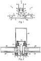
- FIG. 1 shows a holding device according to the invention in Cross-section reproduced.
- the cut surface is vertical to the longitudinal direction of the holding device.
- This includes a holding profile 1 with a cover flange 2 for covering the respective profile of the facade wall and for pressing the Edges of the adjacent filling elements (see Figure 2).
- On the The rear of the cover flange 2 is a first edge web 3 and a second edge web 4 is provided. Furthermore there is in In the area of the first edge web 3, a support web 5 is provided with a parallel to the surface of the cover flange 2 Support flange 6, which in the assembled state Filler holds (see Figure 2).
- the holding profile 1 according to the invention can be in different Shapes and sizes are made. Both different Lengths (in the direction perpendicular to the cross-sectional area shown) as well as different widths of the cover flange 2 and different heights of the webs 3, 4, 5, 7 and 9 are possible.
- the holding profile 1 is, for example extruded aluminum profile.
- the front of the cover flange 2 can be designed as desired.
- a first clamping profile 11 (in not fully assembled Reproduced state) includes one in the assembled state parallel to the surface of the cover flange 2 support flange 12, which has a groove-shaped in a first edge region Receiving web 13 for receiving one end of the central flange 8 of the holding profile 1 and in a second Edge area an insertion web 14 for inserting the holding profile 1 on the second edge web 4.
- the receiving web 13 has a perpendicular to the surface of the support flange 12 Fastening web 15 with an undercut end part 16 on.
- the support flange 12 is with a clamping web 16a Mistake.
- the length of the first clamping profile 11 correspond to the length of the holding profile 1.
- Several first clamping profiles can also be used for a holding profile 1 11 can be provided, for example in the longitudinal direction in Spaced one behind the other.
- the clamping profile 11 is for example an extruded aluminum profile.
- a holding element 17 is in a manner not shown with a Profile of the facade wall can be connected (see Figure 2) and includes one in the assembled state perpendicular to the surface of the cover flange 2 running fastening ends with a first Page 18 and one opposite the first page 18 second side 19, which sides 18, 19 each have an undercut 20 and 21 have for hooking the fastening webs 9, 15 of the holding profile 1 and the first clamping profile 11.
- the length of the holding element 17 (perpendicular to the cross-sectional area) correspond to the length of the holding profile 1.
- a plurality of holding elements 17 can also be used be provided, for example in the longitudinal direction at intervals attached in a row.
- the holding element 17 is for example designed as a stainless steel profile.
- the fastening web 9 on the back of the cover flange 2 of the holding profile 1 is used for lateral hooking of the holding profile 1 in the first side 18 of the facade wall with a profile connectable holding element 17.
- the fastening web 15 on the support flange 12 of the first clamping profile 11 is used for lateral hooking of the first clamping profile 11 into that of the first Page 18 opposite second side 19 of the holding element 17.
- the holding element 17 presses against the End parts 10 and 16 of the fastening webs 9 and 15. This the insertion web 14 at the second edge web 4 against the Back of the cover flange 2 of the holding profile 1 pressed.
- the clamping web 16a improves the clamping bracket further.
- the holding element 17 and / or at least one the mounting webs 9, 15 slightly springy. So the insertion of the first clamping profile 11 on the second edge web 4 of the holding profile 1 and thus the assembly and disassembly the holding device relieved.
- the insertion web 14 of the first clamping profile 11 is small Distance to the edge of the support flange 12 arranged and higher than the second edge web 4 of the holding profile 1. In this way the inserted first clamping profile 11 can be easily released again from the holding profile 1.
- a pointed object for example a screwdriver between the introduced second edge web 4 and the support flange 12.
- the support flange 12 rises relatively to the second edge web 4, and the first clamping profile 11 jumps by the resilient properties of the holding device its inserted position.
- the holding profile 1 In the case of the holding profile 1, the first edge web 3 and the second Edge web 4, the support web 5 with the support flange 6, the Middle web 7 with the middle flange 8 and the fastening web 9 continuously formed on the cover flange 2 over the entire length his.
- the first clamping profile 11 can with the entire length of the Support flange 12 through webs 13, 14, 15 provided his. Thus, the first clamping profile 11 is easy to manufacture.
- the holding device can be several, at intervals with profiles of the facade wall have connectable holding elements 17. Due to the non-continuous design of the holding element 17 material is saved without the safety of the holding device would be affected.
- FIG. 2 shows a section through a facade wall reproduced a holding device according to the invention.
- Facade profile 22 has pairs of longitudinal grooves on its side flanges for receiving filler element seals 23, 24 (pressed rubber profiles) as well as from one to the filler element seals 23, 24 subsequent profile seal 25 on which behind the two pairs of longitudinal grooves in each Is guided.
- the holding element 17 is a resilient Stainless steel profile, which in the the profile seal 25 leading guide grooves is clamped.
- the filling elements consist of insulating glass: a first glass pane 26, 27 and a second glass pane 28, 29, separately by a holding piece 30, 31 and at the edge with a sealing compound 32, 33 provided.
- the cover flange 2 of the holding device is by means of preformed sealing elements 34, 35 (elastic rubber profiles) to the glass panes 26, 27 sealed.
- the holding profile is hooked into the holding element 17.
- the first Clamping profile is hooked into the holding element 17 and on the rear of the holding profile by means of the insertion web 14 inserted at the second edge web 4.
- the first edge web 3 and the Support flange 6 press against the sealing element 34 the edge of the glass sheet 26.
- the support flange 12 presses via the sealing element 35 against the edge of the glass pane 27.
- the sealing element 35 taken away, by means of a screwdriver or the like, as already described, the first clamping profile by overcoming the spring force from its inserted position is pushed out. Even without removing the sealing element 35, the holding device can be released.
- To the screwdriver deforms the sealing element 35 between the second edge web 4 and the support flange 12 introduced and then rotated or pivoted. In In this case, not only must the spring force be overcome, but also the sealing element 35 are deformed.
- FIG. 3 shows a cross section of a further embodiment the holding device according to the invention.
- the holding profile 1 no fastening web.
- a first clamping profile 11 is provided with a support flange 12, which has a fastening web 15 for hooking the first clamping profile to the side 11 into the second side opposite the first side 18 19 of the holding element 17, but also a second, with the first clamping profile 11 mirror-symmetrical clamping profile 36 with a support flange 12 ', which has a fastening web 15 'for hooking the second clamping profile to the side 36 in the first side 18 of the holding element 17.
Landscapes
- Engineering & Computer Science (AREA)
- Architecture (AREA)
- Physics & Mathematics (AREA)
- Electromagnetism (AREA)
- Civil Engineering (AREA)
- Structural Engineering (AREA)
- Finishing Walls (AREA)
- Connection Of Plates (AREA)
Claims (9)
- Dispositif d'arrêt pour des éléments de remplissage dans un mur de façade, comprenant un profilé d'arrêt (1) muni d'une bride de recouvrement (2) et au moins un profilé de serrage (11, 36) apte à venir s'insérer sur le côté dorsal de la bride de recouvrement (2), dans lequel le profilé d'arrêt (1) peut être fixé et à nouveau détaché, à l'aide du ou desdits profilés de serrage (11, 36), à et d'un élément d'arrêt (17) apte à être relié avec un profilé du mur de façade, dans lequel la bride de recouvrement (2) présente des nervures marginales (3, 4), caractérisé en ce que le profilé de serrage (11, 36) présente une bride d'appui (12, 12') s'étendant parallèlement à la surface de la bride de recouvrement (2), qui s'étend jusqu'à la zone marginale externe de la nervure marginale respective (3, 4), la bride d'appui (12, 12') présente une nervure d'insertion (14) et la nervure d'insertion (14) du profilé de serrage (11, 36) est disposée à courte distance du bord de la bride d'appui (12, 12') et est plus haute que la seconde nervure marginale (4) du profilé d'arrêt (1).
- Dispositif d'arrêt selon la revendication 1, caractérisé en ce que la bride d'appui (12, 12') du profilé de serrage (11, 36) présente une nervure de fixation (15, 15') munie d'une contre-dépouille, s'étendant essentiellement perpendiculairement à la surface de la bride de recouvrement (2), pour l'ancrage latéral sur un côté (18, 19) de l'élément d'arrêt (17), dans lequel la nervure de fixation (15, 15') peut être réalisée pour être légèrement élastique.
- Dispositif d'arrêt selon la revendication 1, caractérisé en ce que la bride d'appui (12, 12') du profilé de serrage (11, 36) présente une nervure de serrage (16a).
- Dispositif d'arrêt selon la revendication 1, caractérisé en ce que la bride de recouvrement (2) présente une nervure médiane (7) comprenant une bride médiane (8) s'étendant parallèlement à la surface de la bride de recouvrement (2), dans lequel la bride médiane (8) est réalisée pour venir se loger dans une nervure de réception (13) du profilé de serrage (11, 36), en forme de rainure.
- Dispositif d'arrêt selon l'une quelconque des revendications 1 à 4, caractérisé en ce que la bride de recouvrement (2) présente une nervure de fixation (9) munie d'une contre-dépouille s'étendant essentiellement perpendiculairement à la surface de la bride de recouvrement (2), pour l'ancrage latéral sur un côté (18, 19) de l'élément d'arrêt (17), ainsi qu'une bride d'appui (6) comprenant une nervure d'appui (5), s'étendant parallèlement à la surface de la bride de recouvrement (2), le dispositif d'arrêt pouvant être fixé à l'élément d'arrêt (17) avec un premier profilé de serrage (11).
- Dispositif d'arrêt selon l'une quelconque des revendications 1 à 4, caractérisé en ce qu'un premier profilé de serrage (11) est présent, dans lequel le premier profilé de serrage (11) comprenant la nervure de fixation (15) est prévu pour l'ancrage latéral sur un deuxième côté (19) de l'élément d'arrêt (17) et en ce qu'un second profilé de serrage (36) est présent, dans lequel le second profilé de serrage (36) comprenant la nervure de fixation (15') est prévu pour l'ancrage latéral sur un premier côté (18) de l'élément d'arrêt (17) opposé au second côté (19).
- Dispositif d'arrêt selon la revendication 4, caractérisé en ce que, dans le cas du profilé d'arrêt (1), la première nervure marginale (3) et la deuxième nervure marginale (4), ainsi que la nervure médiane (7) comprenant la bride médiane (7) sont réalisées en continu sur la bride de recouvrement (2).
- Dispositif d'arrêt selon la revendication 5, caractérisé en ce que, dans le cas du profilé d'arrêt (1), la nervure d'appui (5) comprenant la bride d'appui (6), ainsi que la nervure de fixation (9) sont réalisées en continu sur la bride de recouvrement (2).
- Dispositif d'arrêt selon l'une quelconque des revendications 1 à 8, caractérisé en ce que le dispositif d'arrêt est prévu pour la fixation à plusieurs éléments d'arrêt (17) qui peuvent se relier par intervalles avec des profilés du mur de façade.
Applications Claiming Priority (3)
| Application Number | Priority Date | Filing Date | Title |
|---|---|---|---|
| CH163594 | 1994-05-26 | ||
| CH1635/94 | 1994-05-26 | ||
| CH163594 | 1994-05-26 |
Publications (2)
| Publication Number | Publication Date |
|---|---|
| EP0684350A1 EP0684350A1 (fr) | 1995-11-29 |
| EP0684350B1 true EP0684350B1 (fr) | 2000-03-22 |
Family
ID=4215068
Family Applications (1)
| Application Number | Title | Priority Date | Filing Date |
|---|---|---|---|
| EP95107766A Expired - Lifetime EP0684350B1 (fr) | 1994-05-26 | 1995-05-22 | Dispositif de fixation d'un élément de remplissage d'un mur de façade |
Country Status (3)
| Country | Link |
|---|---|
| EP (1) | EP0684350B1 (fr) |
| AT (1) | ATE191041T1 (fr) |
| DE (1) | DE59508023D1 (fr) |
Families Citing this family (2)
| Publication number | Priority date | Publication date | Assignee | Title |
|---|---|---|---|---|
| DE19804925B4 (de) * | 1998-02-07 | 2004-12-02 | Bernhard Steinert | Haltevorrichtung für Füllelemente in einer Wandkonstruktion |
| CH708933A1 (de) * | 2013-12-09 | 2015-06-15 | Berger Metallbau Ag | Haltevorrichtung für Platten. |
Family Cites Families (4)
| Publication number | Priority date | Publication date | Assignee | Title |
|---|---|---|---|---|
| FR1208335A (fr) * | 1958-06-05 | 1960-02-23 | Mur-rideau destiné à être posé sur ou dans une ossature de bâtiment | |
| FR1317750A (fr) * | 1961-03-17 | 1963-05-08 | ||
| NL8801408A (nl) * | 1988-06-01 | 1990-01-02 | Antonius Matheus Franciscus He | Inrichting voor het monteren van glaspanelen. |
| DE4007247A1 (de) * | 1990-03-08 | 1991-09-12 | Peter M Dipl Ing Dinter | Trocken-druck-verglasungsanordnung fuer fassaden- und dach-konstruktionen in pfosten-riegel-bauweise |
-
1995
- 1995-05-22 EP EP95107766A patent/EP0684350B1/fr not_active Expired - Lifetime
- 1995-05-22 AT AT95107766T patent/ATE191041T1/de not_active IP Right Cessation
- 1995-05-22 DE DE59508023T patent/DE59508023D1/de not_active Expired - Fee Related
Also Published As
| Publication number | Publication date |
|---|---|
| ATE191041T1 (de) | 2000-04-15 |
| EP0684350A1 (fr) | 1995-11-29 |
| DE59508023D1 (de) | 2000-04-27 |
Similar Documents
| Publication | Publication Date | Title |
|---|---|---|
| EP0683287B1 (fr) | Rail profilé de fixation d'objets plats | |
| EP0392341B1 (fr) | Fenêtre vitrée, métallique ou en bois | |
| DE20100747U1 (de) | Riegel/Pfosten-Konstruktion | |
| DE202012104033U1 (de) | Haltevorrichtung für eine Brüstungs- oder Geländerplatte sowie Geländer oder Brüstung mit Scheibe | |
| DE29708956U1 (de) | Klemmträger | |
| EP0806575B1 (fr) | Dispositif de fixation | |
| CH650555A5 (de) | Isolierende verbindungsvorrichtung fuer bauplatten tragende zweiteilige metallrahmen. | |
| DE4406913C2 (de) | Klemme | |
| DE4000969C2 (de) | Anordnung zur Befestigung von Gebäudeplatten an Gebäudewänden | |
| EP0067970B1 (fr) | Dispositif de fixation pour éléments de façade | |
| AT516721B1 (de) | Geländer und Verfahren zur Herstellung eines Geländers | |
| EP0684350A1 (fr) | Dispositif de fixation d'un élément de remplissage d'un mur de façade | |
| DE2841204A1 (de) | Haltevorrichtung fuer wand-bekleidungsplatten | |
| EP0330086A1 (fr) | Dispositif d'accouplement d'au moins deux bords longitudinaux de structures en forme de pellicules ou de tissus | |
| DE2119184B2 (de) | Scheibenhalterung eines Fensters o.dgl | |
| EP0674058A1 (fr) | Support de panneaux pour façade, toit, fenêtre ou porte | |
| DE102017000924A1 (de) | Plattenhalter | |
| DE69815904T2 (de) | Klemmverbindungselement zum Verbinden zweier Wandprofile miteinander | |
| DE69002041T2 (de) | Montagesystem und montageelemente für trennwände in bürogebäuden und dergleichen. | |
| EP3244001B1 (fr) | Porte comprenant une piece de serrage commandee par ressort et son procede de montage | |
| DE20100751U1 (de) | Klemmhalter für plattenförmige Bauteile | |
| BE1031648B1 (de) | Befestigungselement für eine Fassadenplatte und Anordnung mit einer Fassadenplatte und dem Befestigungselement | |
| DE20309516U1 (de) | Halteelement für Hohlkammerscheiben | |
| DE10036478A1 (de) | Schnellbefestigungselement | |
| DE102007051058A1 (de) | Befestigungsklammer und System zum Erstellen von Aufbauten |
Legal Events
| Date | Code | Title | Description |
|---|---|---|---|
| PUAI | Public reference made under article 153(3) epc to a published international application that has entered the european phase |
Free format text: ORIGINAL CODE: 0009012 |
|
| AK | Designated contracting states |
Kind code of ref document: A1 Designated state(s): AT BE CH DE FR GB LI LU NL |
|
| 17P | Request for examination filed |
Effective date: 19960510 |
|
| 17Q | First examination report despatched |
Effective date: 19980324 |
|
| GRAG | Despatch of communication of intention to grant |
Free format text: ORIGINAL CODE: EPIDOS AGRA |
|
| GRAG | Despatch of communication of intention to grant |
Free format text: ORIGINAL CODE: EPIDOS AGRA |
|
| GRAH | Despatch of communication of intention to grant a patent |
Free format text: ORIGINAL CODE: EPIDOS IGRA |
|
| GRAH | Despatch of communication of intention to grant a patent |
Free format text: ORIGINAL CODE: EPIDOS IGRA |
|
| GRAA | (expected) grant |
Free format text: ORIGINAL CODE: 0009210 |
|
| AK | Designated contracting states |
Kind code of ref document: B1 Designated state(s): AT BE CH DE FR GB LI LU NL |
|
| PG25 | Lapsed in a contracting state [announced via postgrant information from national office to epo] |
Ref country code: NL Free format text: LAPSE BECAUSE OF FAILURE TO SUBMIT A TRANSLATION OF THE DESCRIPTION OR TO PAY THE FEE WITHIN THE PRESCRIBED TIME-LIMIT Effective date: 20000322 Ref country code: GB Free format text: LAPSE BECAUSE OF FAILURE TO SUBMIT A TRANSLATION OF THE DESCRIPTION OR TO PAY THE FEE WITHIN THE PRESCRIBED TIME-LIMIT Effective date: 20000322 Ref country code: FR Free format text: LAPSE BECAUSE OF FAILURE TO SUBMIT A TRANSLATION OF THE DESCRIPTION OR TO PAY THE FEE WITHIN THE PRESCRIBED TIME-LIMIT Effective date: 20000322 |
|
| REF | Corresponds to: |
Ref document number: 191041 Country of ref document: AT Date of ref document: 20000415 Kind code of ref document: T |
|
| REG | Reference to a national code |
Ref country code: CH Ref legal event code: EP |
|
| REF | Corresponds to: |
Ref document number: 59508023 Country of ref document: DE Date of ref document: 20000427 |
|
| PG25 | Lapsed in a contracting state [announced via postgrant information from national office to epo] |
Ref country code: LU Free format text: LAPSE BECAUSE OF NON-PAYMENT OF DUE FEES Effective date: 20000522 Ref country code: AT Free format text: LAPSE BECAUSE OF NON-PAYMENT OF DUE FEES Effective date: 20000522 |
|
| PG25 | Lapsed in a contracting state [announced via postgrant information from national office to epo] |
Ref country code: LI Free format text: LAPSE BECAUSE OF NON-PAYMENT OF DUE FEES Effective date: 20000531 Ref country code: CH Free format text: LAPSE BECAUSE OF NON-PAYMENT OF DUE FEES Effective date: 20000531 Ref country code: BE Free format text: LAPSE BECAUSE OF NON-PAYMENT OF DUE FEES Effective date: 20000531 |
|
| EN | Fr: translation not filed | ||
| NLV1 | Nl: lapsed or annulled due to failure to fulfill the requirements of art. 29p and 29m of the patents act | ||
| GBV | Gb: ep patent (uk) treated as always having been void in accordance with gb section 77(7)/1977 [no translation filed] |
Effective date: 20000322 |
|
| BERE | Be: lapsed |
Owner name: ALU MENZIKEN INDUSTRIE A.G. Effective date: 20000531 |
|
| REG | Reference to a national code |
Ref country code: CH Ref legal event code: PL |
|
| PLBE | No opposition filed within time limit |
Free format text: ORIGINAL CODE: 0009261 |
|
| STAA | Information on the status of an ep patent application or granted ep patent |
Free format text: STATUS: NO OPPOSITION FILED WITHIN TIME LIMIT |
|
| 26N | No opposition filed | ||
| PG25 | Lapsed in a contracting state [announced via postgrant information from national office to epo] |
Ref country code: DE Free format text: LAPSE BECAUSE OF NON-PAYMENT OF DUE FEES Effective date: 20010403 |