EP0684880B1 - Ein- und ausrückbare bremse am tragarm einer absaugeinrichtung - Google Patents
Ein- und ausrückbare bremse am tragarm einer absaugeinrichtung Download PDFInfo
- Publication number
- EP0684880B1 EP0684880B1 EP92905458A EP92905458A EP0684880B1 EP 0684880 B1 EP0684880 B1 EP 0684880B1 EP 92905458 A EP92905458 A EP 92905458A EP 92905458 A EP92905458 A EP 92905458A EP 0684880 B1 EP0684880 B1 EP 0684880B1
- Authority
- EP
- European Patent Office
- Prior art keywords
- arm
- actuator
- rod
- extractor
- arrangement
- Prior art date
- Legal status (The legal status is an assumption and is not a legal conclusion. Google has not performed a legal analysis and makes no representation as to the accuracy of the status listed.)
- Expired - Lifetime
Links
- 238000000605 extraction Methods 0.000 claims abstract description 5
- 238000006073 displacement reaction Methods 0.000 claims 1
- 230000000694 effects Effects 0.000 description 3
- 238000003466 welding Methods 0.000 description 3
- 230000005611 electricity Effects 0.000 description 2
- 239000012530 fluid Substances 0.000 description 2
- 239000002184 metal Substances 0.000 description 2
- 229910000831 Steel Inorganic materials 0.000 description 1
- 230000006835 compression Effects 0.000 description 1
- 238000007906 compression Methods 0.000 description 1
- 239000003517 fume Substances 0.000 description 1
- 239000000463 material Substances 0.000 description 1
- 230000002787 reinforcement Effects 0.000 description 1
- 239000010959 steel Substances 0.000 description 1
- 239000000126 substance Substances 0.000 description 1
- 239000000725 suspension Substances 0.000 description 1
- 239000003496 welding fume Substances 0.000 description 1
Images

Classifications
-
- B—PERFORMING OPERATIONS; TRANSPORTING
- B08—CLEANING
- B08B—CLEANING IN GENERAL; PREVENTION OF FOULING IN GENERAL
- B08B15/00—Preventing escape of dirt or fumes from the area where they are produced; Collecting or removing dirt or fumes from that area
- B08B15/002—Preventing escape of dirt or fumes from the area where they are produced; Collecting or removing dirt or fumes from that area using a central suction system, e.g. for collecting exhaust gases in workshops
Definitions
- the subject invention concerns an arrangement in extractor cranes comprising an arm arranged to mount an extractor and/or some other equipment, said arm being articulated by means of one of its arms to a support with the intermediary of a mounting bracket, so as to be allowed to pivot or swing essentially in the horizontal plane, a retaining device acting between the arm and the bracket or the support for the purpose of maintaining the arm in the set position of pivot thereof.
- a device of the kind referred to is generally known from SE, C, 7706374-1, corresponding to SE, B, 423 059.
- the subject invention proposes to fit the retaining device with a retaining element which is actuated by means of a power actuator arranged, by overriding the retaining force, to allow the desired pivotal movement of the arm, and to provide for remote control of the actuator from a place spaced from said one end of the arm.
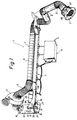
- the extractor crane illustrated in the drawing figures and generally designated by reference 1 is fitted with an essentially horizontally directed arm 2 of a suitable material, preferably a tubular steel section.
- the arm 2 may be a one-piece section, as illustrated, or consist of two or several mutually articulated sections, depending on the desired range of the extractor crane 1.
- the arm 2 is arranged to serve as a support or a suspension means for a fume extractor 3 of a prior-art design including a fan 4, hoses 5, tubes 6, and a hood 7 for extraction of the air-polluting substances (welding fumes) that are generated for instance during welding operations, and/or optionally for other equipment, such as welding-wire feeders 8, cables, hand tools and the like.
- a fume extractor 3 of a prior-art design including a fan 4, hoses 5, tubes 6, and a hood 7 for extraction of the air-polluting substances (welding fumes) that are generated for instance during welding operations, and/or optionally for other equipment, such as welding-wire feeders 8, cables, hand tools and the like.
- the arm 2 is fitted with a vertically directed bearing tube 10, preferably secured to the arm through welding, which bearing tube 10 encloses and by means of suitable bearings 11 is mounted on a vertically directed spindle 12, thus allowing pivotal movements of the arm 2 essentially in the horizontal plane.
- Nuts 13 or similar means secure the spindle 12 non-rotationally between two vertically spaced and horizontally projecting lugs 15 which are secured, preferably through welding, to a mounting bracket 14.
- the mounting bracket 14 consists of a flat plate which by means of bolts 16 or similar fasteners extending through holes made in the plate, may be mounted on a support 17, preferably a wall, a stanchion or the like.
- a retaining device is arranged so as to act between said one end 9 of the arm 2 and, in the embodiment illustrated, the bracket 14.
- the retaining device 18 comprises a retaining element 19 which is arranged to be actuated by a power actuator 20 for the purpose of overriding the retaining force, thus allowing the arm 2 to be pivoted as desired.
- the power actuator 20 is remote-controlled from a point to be described in closer detail in the following, spaced from the said one end 9 of the arm 2.
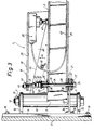
- the retaining element 19 is equipped with a friction element 21 which is arranged to be displaced inside the arm 2 at the said one end 9 thereof and which is arranged to be actuated by the acctuator 20 into and out of frictional engagement with a back-up or counter element 22 connected with the bracket 14.
- the friction element 21 consists of two circular friction washers 23 disposed at one, the lower, end of a rod 24 so as to sandwich the back-up element 22 between them.
- the upper friction washer 23 is situated between the lower face 25 of the arm 2 and the upper face of the back-up element 22 whereas the lower friction washer 23 is situated between the lower face of the back-up element 22 and a support washer 27 mounted in abutment against a head 26 of the rod 24.
- the rod 24 is made from metal and forms part of the retaining element 19. In the manner illustrated, the rod 24 extends in an essentially vertical direction and is displaceable lengthwise, through the arm 2, through holes 28 formed in the latter, the said lower end of the rod 24 which supports the friction washers 23 and the support washer 27, projecting below the lower face 25 of the arm 2.
- the rod 24 supports a spring means 33 which is inserted on the rod 24 between an abutment 29 on the arm 2, in the subject case formed by the upper face 30 of the arm 20, and a set nut 31 and its associated tightening nut 32.
- the spring means 33 is designed as a helical compression spring but it could equally well be in the form of two or more cup springs, a rubber spring or the like.
- the back-up element 22 in accordance with the embodiment illustrated is designed as a crescent-shaped plate 34 which is positioned below the arm and which is attached at its free ends to the bracket 14 by means of bolts 35 or similar fastening means so as to project essentially horizontally away from the bracket 14.
- the plate 34 could be given another configuration than the crescent-shape but irrespective of its configuration it is formed with an arcuate slot 36 having a radius the centre of which essentially coincides with the pivot centre of the arm 2 about the spindle 12.
- the spring means 33 urges the friction washers 23 into engagement with the upper and lower faces of the plate 34 in order to provide the retaining effect, whereby the retaining force, i.e. the friction force between the friction washers 23 and the plate 34, may be set by adjusting the spring force by setting the set nut 31.
- the upper free end 37 of the rod 24 may be actuated by the actuator 20 in order to effect disengagement of the friction washers 23 from the upper and lower faces of the plate 34 against the action of the spring means 33 in order to override the retaining force.
- the actuator 20 is mounted at one end of a double-arm yoke 38, which is made of sheet metal and which has a cross-sectional configuration essentially in the form of an inverted U comprising an upper web 39 and two downwardly directed lateral flanges 40.
- the yoke 38 At the opposite end of the yoke 38, in alignment with the previously mentioned second, upper end 37 of the rod 24, the yoke is fitted with an actuating means 41 which is mounted in the yoke web 39.
- the actuating means is in the form of a bolt 43 with a locking nut 42 and is screwed into the yoke web, and the bolt head 44 may be displaced into engagement with the upper end 37 of the rod 24 for actuation thereof, as will be described in closer detail in the following.
- a pivot through-pin 46 intermediate the yoke ends pivotally mounts the yoke 38 via the lateral flanges of the latter, to reinforcement flanges 45 formed on the arm 2 of the extractor crane 1 to allow pivotal instruments of the yoke about an essentially horizontal axis.
- the actuator 20 is fitted with an actuating element 47 on its side facing the arm 2, which actuating element is arranged to move lengthwise or outwards and inwards and which upon remote control of the actuator 20 moves outwards and into engagement with the upper face 30 of the arm 2 in order to turn the yoke 38 counter-clockwise A about the pivot 46, thus displacing, via the actuating means 41, the rod 24 of the retaining element 19 downwards against the action of the spring means 33 with consequential disengagement of the friction washers 23 from the plate 34.
- control unit 48 which in accordance with the embodiment illustrated is positioned at the free end of the extractor crane 1, so as to be easily accessible to the crane operator.
- control unit 48 preferably is positioned on or adjacent the extraction hood 7 of the extractor 3.
- control unit 48 may be positioned elsewhere, remote from the retaining device 18 and may for instance be carried by the operator and be connected to the retaining device in a wireless mode or by means of cables.
- the actuator 20 proper may be designed in a variety of different ways. In accordance with one embodiment it consists of a pneumatic cylinder and in accordance with another of a hydraulic cylinder, the cylinder piston rod preferably forming the actuating element 47. According to a third alternative, it consists of an electro-magnet with a displaceable armature, the latter in this case preferably forming the actuating element 47. Further alternative embodiments of the actuator 20 obviously are possible, the essential feature being the ability of the actuator to pivot the yoke in the manner described above.
- control unit 48 may consist of a pneumatic or hydraulic valve, a switch or a similar means connected to the actuator 20 via supply lines 49 for pressurized air, hydraulic fluid, electricity etcetera.
- the actuator 20 includes a manually operable control element 50 of a suitable type, such as a control lever, a push button or the like.
- the actuator 20 In order to supply the actuator 20 and the control unit with the required energy (pressurized air, hydraulic fluid, electricity and so on) the actuator 20 is connected in any suitable manner to an external source of energy, not shown.
- the yoke 38 may be dispensed with and the actuator 20 be arranged to act directly, by means of its actuating element 47, on the rod 24 of the retaining device 18 or even form the rod, in which case the actuator is rigidly mounted on the arm 2.
- the retaining device 18 and the actuator 20 may constitute a unit in the form of e.g. a horizontally directed piston- and cylinder unit the cylinder of which is hinged to the bracket 14 and the piston rod of which to the arm 2 or vice versa, in order to pivot and retain, respectively, the arm in the set position of pivotement, or a rotational motor the output shaft of which is connected to or forms part of the bearing tube 10 to turn and retain the latter, respectively, and thus to effect pivotal movement and retainment of the arm in the set pivotal position.
- a horizontally directed piston- and cylinder unit the cylinder of which is hinged to the bracket 14 and the piston rod of which to the arm 2 or vice versa, in order to pivot and retain, respectively, the arm in the set position of pivotement, or a rotational motor the output shaft of which is connected to or forms part of the bearing tube 10 to turn and retain the latter, respectively, and thus to effect pivotal movement and retainment of the arm in the set pivotal position.
Landscapes
- Pivots And Pivotal Connections (AREA)
- Manipulator (AREA)
- Hooks, Suction Cups, And Attachment By Adhesive Means (AREA)
- Jib Cranes (AREA)
- Sampling And Sample Adjustment (AREA)
- Quick-Acting Or Multi-Walled Pipe Joints (AREA)
- Load-Engaging Elements For Cranes (AREA)
- Ship Loading And Unloading (AREA)
- Braking Arrangements (AREA)
Claims (9)
- Anordnung in Absaug-Kranen (1) umfassend einen Arm (2), der zum Anbringen einer Absaugeinrichtung (3) und/oder einer anderen Einrichtung (8) vorgesehen ist, wobei der Arm (2) an einem (9) seiner Enden über eine Befestigungshalterung (14) an einem Tragelement (17) gelenkig angebracht ist, so daß er im wesentlichen in horizontaler Ebene verschwenkbar ist, eine zwischen dem Arm (2) und der Befestigungshalterung oder dem Tragelement (17) wirkende Festhaltevorrichtung (18), um den Arm (2) in dessen eingestellten Schwenkposition zu halten, und umfassend ein Halteelement (19), das angeordnet ist, um mittels eines Stellorgans (20) betätigt zu werden, das durch Überwindung der Haltekraft es zuläßt, daß der Arm (2) in gewünschter Weise verschwenkt werden kann, und das von einem Punkt, der von dem einen Ende des Arms (2) beabstandet ist, ferngesteuert ist, dadurch gekennzeichnet, daß das Halteelement (19) ein Reibelement (21) enthält, das an dem einen Armende (9) im Arm (2) verschieblich angeordnet ist und das desgleichen angeordnet ist, um mit einem Gegenelement (22), das mit der Befestigungshalterung (14) oder dem Tragelement (17) verbunden ist, in und aus dem Reibschluß verschoben zu werden.
- Anordnung nach Anspruch 1, dadurch gekennzeichnet, daß das Reibelement (21) in Form zumindest einer Spannscheibe (23) vorliegt und an einem Ende einer Stange (24) positioniert ist, wobei letztere einen Teil des Halteelementes (19) bildet und sich im wesentlichen vertikal erstreckt und in seiner Längsrichtung durch den Arm (2) verschieblich angeordnet ist, wobei das eine Ende, das die Spannscheibe/Spannscheiben (23) trägt, vom Arm (2) nach unten vorsteht.
- Anordnung nach Anspruch 2, dadurch gekennzeichnet, daß die Stange (24) zwischen ihren Enden ein Federmittel (33) trägt, das zwischen einem Abstützmittel (29) auf dem Arm (2) und einem Einstellmittel (31) auf der Stange (24) gehalten wird.
- Anordnung nach einem der vorhergehenden Ansprüche, dadurch gekennzeichnet, daß das Gegenelement (2) die Form einer Platte (34) hat, die unterhalb des Arms (2) positioniert ist und einen bogenförmigen, im wesentlichen horizontal gerichteten Schlitz (36) aufweist, dessen Radius seinen Mittelpunkt im wesentlichen im Drehpunkt des Arms (2) hat, wobei sich das eine Ende der Stange (24) durch den Schlitz (36) hindurch erstreckt und die Spannscheibe/Spannscheiben (23) auf der Unterseite der Platte (34) liegen oder die Platte dazwischen einschließen.
- Anordnung nach einem der vorhergehenden Ansprüche, dadurch gekennzeichnet, daß zum Festhalten das Federelement (33) die Spannscheibe/Spannscheiben (23) mit der Ober-/Unterseite der Platte in Reibschluß drückt, und daß die Stange (24) angeordnet ist, um durch das Stellorgan (20) an ihrem gegenüberliegenden Ende (37) gegen die Federkraft des Federmittels (33) bewegt zu werden, um die Spannscheibe/Spannscheiben aus dem Reibschluß mit der Platte zu lösen und die Haltekraft zu überwinden.
- Anordnung nach einem der vorhergehenden Ansprüche, dadurch gekennzeichnet, daß das Stellorgan (20) an einem Ende einer Wippe (38) angeordnet ist, deren gegenüberliegendes Ende (37) mit einem mit dem anderen Ende der Stange (24) ausgerichteten Betätigungsmittel (41) versehen ist, wobei die Wippe an dem Arm (2) zwischen dessen Enden verdrehbar angebracht ist, so daß sie um eine im wesentlichen horizontale Achse verdrehbar ist, wobei das Stellorgan (20) mit einem Betätigungselement (47) ausgebildet ist, das längs bewegbar ist und das durch Fernsteuerung des Stellorgans (20) in Anlage gegen die Oberseite (30) des Arms (2) bewegt werden kann, um die Wippe (38) zu verdrehen und somit die Stange (24) über das Betätigungsmittel (41) gegen die Federkraft des Federmittels (33) abwärts zu verschieben, wodurch der Reibschluß der Spannscheibe/Spannscheiben (23) mit der Platte (22) gelöst wird.
- Anordnung nach einem der vorhergehenden Ansprüche, dadurch gekennzeichnet, daß die Fernsteuerung des Stellorgans (20) mittels einer an dem gegenüberliegenden freien Ende des Arms (2) des Absaug-Krans (1) liegenden Steuereinheit (48) bewirkt wird, um so für den Kranführer leicht zugänglich zu sein, vorzugsweise auf oder neben einer Absaughaube (7), in den Fällen, bei denen der Absaug-Kran (1) mit einer Absaugeinrichtung (3) ausgerüstet ist, die mit solch einer Absaughaube versehen ist.
- Anordnung nach einem der vorhergehenden Ansprüche, dadurch gekennzeichnet, daß das Stellorgan (20) aus einem Pneumatik- oder Hydraulikzylinder besteht, dessen Kolbenstange ein Betätigungselement (47) bildet, oder aus einem Elektromagnet besteht, dessen bewegbarer Anker das Betätigungselement (47) bildet, und daß die Steuereinheit (48) aus einem Pneumatik- oder Hydraulikventil oder aus einem Schalter mit manuell betätigbarem Steuerelement (50) besteht, vorzugsweise ein Steuerhebel oder Druckknopf, wobei die Steuereinheit (48) über Zuleitungen (49) mit dem Stellorgan (20) verbunden ist.
- Anordnung nach einem der vorhergehenden Ansprüche, dadurch gekennzeichnet, daß das Stellorgan (20) an eine externe Energiequelle angeschlossen ist.
Applications Claiming Priority (3)
| Application Number | Priority Date | Filing Date | Title |
|---|---|---|---|
| SE9100423 | 1991-02-13 | ||
| SE9100423A SE466641C (sv) | 1991-02-13 | 1991-02-13 | Anordning vid utsugskran |
| PCT/SE1992/000051 WO1992014561A1 (en) | 1991-02-13 | 1992-01-28 | An arrangement in extractor cranes |
Publications (2)
| Publication Number | Publication Date |
|---|---|
| EP0684880A1 EP0684880A1 (de) | 1995-12-06 |
| EP0684880B1 true EP0684880B1 (de) | 1997-12-03 |
Family
ID=20381878
Family Applications (1)
| Application Number | Title | Priority Date | Filing Date |
|---|---|---|---|
| EP92905458A Expired - Lifetime EP0684880B1 (de) | 1991-02-13 | 1992-01-28 | Ein- und ausrückbare bremse am tragarm einer absaugeinrichtung |
Country Status (10)
| Country | Link |
|---|---|
| US (1) | US5560583A (de) |
| EP (1) | EP0684880B1 (de) |
| AT (1) | ATE160709T1 (de) |
| AU (1) | AU1277892A (de) |
| DE (1) | DE69223424T2 (de) |
| DK (1) | DK0684880T3 (de) |
| ES (1) | ES2111633T3 (de) |
| GR (1) | GR3026268T3 (de) |
| SE (1) | SE466641C (de) |
| WO (1) | WO1992014561A1 (de) |
Families Citing this family (20)
| Publication number | Priority date | Publication date | Assignee | Title |
|---|---|---|---|---|
| AUPN442895A0 (en) * | 1995-07-28 | 1995-08-17 | Ozone Manufacturing Pty Ltd | Flexible cantilevered hollow arm |
| IT1291164B1 (it) † | 1997-03-04 | 1998-12-29 | Coral Spa | Condotto universale di convogliamento di fumi o gas nocivi da un posto di lavorazione. |
| CA2214549A1 (en) | 1997-09-02 | 1999-03-02 | Henning Hansen | Support arm |
| DE10310205A1 (de) * | 2003-03-08 | 2004-10-07 | Daimlerchrysler Ag | Wasserstoffablassleitung |
| WO2005037166A2 (en) * | 2003-10-13 | 2005-04-28 | Hill-Rom Services, Inc. | Brake system for patient care equipment support arm |
| US7204462B2 (en) * | 2004-04-23 | 2007-04-17 | Certainteed Corporation | Expanding hose holder |
| US7770247B2 (en) * | 2005-05-02 | 2010-08-10 | Hill-Rom Services, Inc. | Brake system for wall arm |
| US7475855B2 (en) * | 2005-07-25 | 2009-01-13 | Cormark, Inc. | Sign mount with unpinned hinge |
| SE529098C2 (sv) * | 2005-09-09 | 2007-05-02 | P H Nederman & Co Ab | Utsugningshuv samt metod för hopmontering av densamma |
| KR100779966B1 (ko) * | 2007-01-08 | 2007-11-27 | 삼성전기주식회사 | 동력전달장치 |
| US20100123049A1 (en) * | 2008-11-20 | 2010-05-20 | Lehman Vincent M | Medical gas hose support system |
| CA2753531C (en) * | 2009-02-24 | 2017-09-12 | Michael Giarrizzo, Jr. | Vehicle collision repair booth |
| US7997545B2 (en) * | 2009-07-07 | 2011-08-16 | Holland Rodney W | Pivoting support structure |
| WO2011048154A1 (de) | 2009-10-23 | 2011-04-28 | Heinz Schlegel | Krananordnung mit absaugeinrichtung |
| CN201902001U (zh) * | 2010-05-18 | 2011-07-20 | 福迈克斯有限公司 | 用于排出局部区域空气的装置和系统 |
| US8657324B2 (en) * | 2012-05-29 | 2014-02-25 | James Hofer | Tractor-trailer hose support |
| JP2015047014A (ja) * | 2013-08-28 | 2015-03-12 | 河村電器産業株式会社 | 充電ケーブル支持アーム |
| US10875061B2 (en) * | 2016-08-10 | 2020-12-29 | Pat Technology Systems Inc. | Fume extraction apparatus with movable extraction aperture |
| US10647310B2 (en) | 2017-07-31 | 2020-05-12 | Ttx Company | Trainline support assembly |
| US11318509B2 (en) * | 2017-11-06 | 2022-05-03 | Air Systems Design, Inc. | Dust hood |
Citations (1)
| Publication number | Priority date | Publication date | Assignee | Title |
|---|---|---|---|---|
| GB1256231A (en) * | 1968-07-30 | 1971-12-08 | Newton Collins Ltd | Improvements relating to dust extraction apparatus |
Family Cites Families (9)
| Publication number | Priority date | Publication date | Assignee | Title |
|---|---|---|---|---|
| US3096933A (en) * | 1961-03-29 | 1963-07-09 | Bora Ion | Portable fume exhaust fan apparatus |
| US3576988A (en) * | 1968-06-06 | 1971-05-04 | Phoenix Products Co Inc | Adjustable stop for swingable floodlights |
| GB1515056A (en) * | 1975-09-08 | 1978-06-21 | Shikimi Y | Apparatus for mounting an object on an upright |
| SE423059B (sv) * | 1977-06-01 | 1982-04-13 | Plymoth Pp Ab | Bromsanordning vid upphengningsarm |
| SE435240B (sv) * | 1980-09-11 | 1984-09-17 | Tomas B Juhlin | Anordning for avlegsnande av fororeningar uppstaende i samband med svetsning |
| SE451433B (sv) * | 1982-09-10 | 1987-10-12 | Fumex Ab | Punktutsug |
| SU1516083A2 (ru) * | 1987-12-14 | 1989-10-23 | Белгородский технологический институт строительных материалов им.И.А.Гришманова | Устройство дл поддержки шланга |
| US4886237A (en) * | 1988-09-23 | 1989-12-12 | Dennis Robert R | Universal articulatable support for retaining intravenous stands in medical applications |
| CA1322318C (en) * | 1989-03-14 | 1993-09-21 | Jacob R. Wiebe | Supply hose support arrangement for car wash |
-
1991
- 1991-02-13 SE SE9100423A patent/SE466641C/sv not_active IP Right Cessation
-
1992
- 1992-01-28 AU AU12778/92A patent/AU1277892A/en not_active Abandoned
- 1992-01-28 AT AT92905458T patent/ATE160709T1/de not_active IP Right Cessation
- 1992-01-28 ES ES92905458T patent/ES2111633T3/es not_active Expired - Lifetime
- 1992-01-28 DK DK92905458T patent/DK0684880T3/da active
- 1992-01-28 WO PCT/SE1992/000051 patent/WO1992014561A1/en not_active Ceased
- 1992-01-28 US US08/104,061 patent/US5560583A/en not_active Expired - Fee Related
- 1992-01-28 EP EP92905458A patent/EP0684880B1/de not_active Expired - Lifetime
- 1992-01-28 DE DE69223424T patent/DE69223424T2/de not_active Expired - Lifetime
-
1998
- 1998-02-27 GR GR980400446T patent/GR3026268T3/el unknown
Patent Citations (1)
| Publication number | Priority date | Publication date | Assignee | Title |
|---|---|---|---|---|
| GB1256231A (en) * | 1968-07-30 | 1971-12-08 | Newton Collins Ltd | Improvements relating to dust extraction apparatus |
Also Published As
| Publication number | Publication date |
|---|---|
| GR3026268T3 (en) | 1998-05-29 |
| SE9100423D0 (sv) | 1991-02-13 |
| AU1277892A (en) | 1992-09-15 |
| DK0684880T3 (da) | 1998-08-10 |
| US5560583A (en) | 1996-10-01 |
| SE466641B (sv) | 1992-03-16 |
| ES2111633T3 (es) | 1998-03-16 |
| WO1992014561A1 (en) | 1992-09-03 |
| SE466641C (sv) | 1996-12-23 |
| DE69223424D1 (de) | 1998-01-15 |
| DE69223424T2 (de) | 1998-06-04 |
| EP0684880A1 (de) | 1995-12-06 |
| ATE160709T1 (de) | 1997-12-15 |
| SE9100423L (sv) | 1992-03-16 |
Similar Documents
| Publication | Publication Date | Title |
|---|---|---|
| US5560583A (en) | Apparatus for supporting and positioning equipment | |
| US5377913A (en) | Hydraulic robot jet lance | |
| US5361646A (en) | Locking mechanism | |
| EP1551748B1 (de) | EINEN SCHWINGUNGSDûMPFER BETREFFENDE ANORDNUNG | |
| CN115182593B (zh) | 抹平设备 | |
| US20110001102A1 (en) | Band brake | |
| CA2219794A1 (en) | Counterbalanced table mechanism | |
| US5465946A (en) | Positioning fixture for welding operations having a lockable ball joint | |
| US4449263A (en) | Powered folding support structure | |
| US3774462A (en) | Valve actuator | |
| US12133774B2 (en) | Support arm articulation apparatus and support system for a medical device | |
| CA2564336C (en) | Self-locking braking device for rotary shafts, and relevant applications | |
| US4020926A (en) | Brake apparatus including pressed or stamped components | |
| US4727691A (en) | Automatic swinging and locking apparatus and method | |
| US4273231A (en) | Chute brake for concrete mixing vehicles | |
| CA2482117A1 (en) | Electrically operated actuator provided with rocking arm | |
| DE2918010A1 (de) | Pneumatisches balanciergeraet | |
| US6393931B1 (en) | Decluthable manual override gearbox | |
| US904148A (en) | Lever and ratchet for vehicle-brakes. | |
| JP3753329B2 (ja) | ベンデングユニットの駆動装置 | |
| KR20220047326A (ko) | 야금 용기의 스토퍼 클로져용 구동 장치 | |
| US6682061B2 (en) | Actuator system for positioning a workpiece | |
| CN218647361U (zh) | 一种工程机械控制手柄 | |
| CN212832330U (zh) | 一种可方便调节平衡的吊具 | |
| CN211207961U (zh) | 一种工业噪音控制装置 |
Legal Events
| Date | Code | Title | Description |
|---|---|---|---|
| PUAI | Public reference made under article 153(3) epc to a published international application that has entered the european phase |
Free format text: ORIGINAL CODE: 0009012 |
|
| 17P | Request for examination filed |
Effective date: 19930811 |
|
| AK | Designated contracting states |
Kind code of ref document: A1 Designated state(s): AT BE CH DE DK ES FR GB GR IT LI LU NL SE |
|
| GRAG | Despatch of communication of intention to grant |
Free format text: ORIGINAL CODE: EPIDOS AGRA |
|
| 17Q | First examination report despatched |
Effective date: 19970114 |
|
| GRAH | Despatch of communication of intention to grant a patent |
Free format text: ORIGINAL CODE: EPIDOS IGRA |
|
| GRAH | Despatch of communication of intention to grant a patent |
Free format text: ORIGINAL CODE: EPIDOS IGRA |
|
| GRAA | (expected) grant |
Free format text: ORIGINAL CODE: 0009210 |
|
| AK | Designated contracting states |
Kind code of ref document: B1 Designated state(s): AT BE CH DE DK ES FR GB GR IT LI LU NL SE |
|
| REF | Corresponds to: |
Ref document number: 160709 Country of ref document: AT Date of ref document: 19971215 Kind code of ref document: T |
|
| REG | Reference to a national code |
Ref country code: CH Ref legal event code: EP |
|
| PGFP | Annual fee paid to national office [announced via postgrant information from national office to epo] |
Ref country code: SE Payment date: 19971230 Year of fee payment: 7 |
|
| PGFP | Annual fee paid to national office [announced via postgrant information from national office to epo] |
Ref country code: GR Payment date: 19980115 Year of fee payment: 7 |
|
| REF | Corresponds to: |
Ref document number: 69223424 Country of ref document: DE Date of ref document: 19980115 |
|
| PG25 | Lapsed in a contracting state [announced via postgrant information from national office to epo] |
Ref country code: LU Free format text: LAPSE BECAUSE OF NON-PAYMENT OF DUE FEES Effective date: 19980128 |
|
| PGFP | Annual fee paid to national office [announced via postgrant information from national office to epo] |
Ref country code: FR Payment date: 19980128 Year of fee payment: 7 |
|
| PGFP | Annual fee paid to national office [announced via postgrant information from national office to epo] |
Ref country code: NL Payment date: 19980130 Year of fee payment: 7 Ref country code: DE Payment date: 19980130 Year of fee payment: 7 |
|
| ITF | It: translation for a ep patent filed | ||
| PG25 | Lapsed in a contracting state [announced via postgrant information from national office to epo] |
Ref country code: SE Free format text: LAPSE BECAUSE OF FAILURE TO SUBMIT A TRANSLATION OF THE DESCRIPTION OR TO PAY THE FEE WITHIN THE PRESCRIBED TIME-LIMIT Effective date: 19980303 |
|
| REG | Reference to a national code |
Ref country code: CH Ref legal event code: NV Representative=s name: R. A. EGLI & CO. PATENTANWAELTE |
|
| REG | Reference to a national code |
Ref country code: ES Ref legal event code: FG2A Ref document number: 2111633 Country of ref document: ES Kind code of ref document: T3 |
|
| PGFP | Annual fee paid to national office [announced via postgrant information from national office to epo] |
Ref country code: BE Payment date: 19980320 Year of fee payment: 7 |
|
| ET | Fr: translation filed | ||
| PGFP | Annual fee paid to national office [announced via postgrant information from national office to epo] |
Ref country code: CH Payment date: 19980402 Year of fee payment: 7 |
|
| REG | Reference to a national code |
Ref country code: DK Ref legal event code: T3 |
|
| PLBE | No opposition filed within time limit |
Free format text: ORIGINAL CODE: 0009261 |
|
| STAA | Information on the status of an ep patent application or granted ep patent |
Free format text: STATUS: NO OPPOSITION FILED WITHIN TIME LIMIT |
|
| 26N | No opposition filed | ||
| PGFP | Annual fee paid to national office [announced via postgrant information from national office to epo] |
Ref country code: GB Payment date: 19990108 Year of fee payment: 8 |
|
| PGFP | Annual fee paid to national office [announced via postgrant information from national office to epo] |
Ref country code: ES Payment date: 19990113 Year of fee payment: 8 |
|
| PGFP | Annual fee paid to national office [announced via postgrant information from national office to epo] |
Ref country code: AT Payment date: 19990114 Year of fee payment: 8 |
|
| PGFP | Annual fee paid to national office [announced via postgrant information from national office to epo] |
Ref country code: DK Payment date: 19990120 Year of fee payment: 8 |
|
| PG25 | Lapsed in a contracting state [announced via postgrant information from national office to epo] |
Ref country code: DE Free format text: LAPSE BECAUSE OF THE APPLICANT RENOUNCES Effective date: 19990126 |
|
| PG25 | Lapsed in a contracting state [announced via postgrant information from national office to epo] |
Ref country code: LI Free format text: LAPSE BECAUSE OF NON-PAYMENT OF DUE FEES Effective date: 19990131 Ref country code: GR Free format text: LAPSE BECAUSE OF NON-PAYMENT OF DUE FEES Effective date: 19990131 Ref country code: CH Free format text: LAPSE BECAUSE OF NON-PAYMENT OF DUE FEES Effective date: 19990131 Ref country code: BE Free format text: LAPSE BECAUSE OF NON-PAYMENT OF DUE FEES Effective date: 19990131 |
|
| PG25 | Lapsed in a contracting state [announced via postgrant information from national office to epo] |
Ref country code: DK Free format text: LAPSE BECAUSE OF NON-PAYMENT OF DUE FEES Effective date: 19990202 |
|
| BERE | Be: lapsed |
Owner name: PLYMOVENT A.B. Effective date: 19990131 |
|
| PG25 | Lapsed in a contracting state [announced via postgrant information from national office to epo] |
Ref country code: NL Free format text: LAPSE BECAUSE OF NON-PAYMENT OF DUE FEES Effective date: 19990801 |
|
| REG | Reference to a national code |
Ref country code: CH Ref legal event code: PL |
|
| PG25 | Lapsed in a contracting state [announced via postgrant information from national office to epo] |
Ref country code: FR Free format text: LAPSE BECAUSE OF NON-PAYMENT OF DUE FEES Effective date: 19990930 |
|
| REG | Reference to a national code |
Ref country code: FR Ref legal event code: ST |
|
| PG25 | Lapsed in a contracting state [announced via postgrant information from national office to epo] |
Ref country code: GB Free format text: LAPSE BECAUSE OF NON-PAYMENT OF DUE FEES Effective date: 20000128 Ref country code: AT Free format text: LAPSE BECAUSE OF NON-PAYMENT OF DUE FEES Effective date: 20000128 |
|
| PG25 | Lapsed in a contracting state [announced via postgrant information from national office to epo] |
Ref country code: ES Free format text: LAPSE BECAUSE OF NON-PAYMENT OF DUE FEES Effective date: 20000129 |
|
| REG | Reference to a national code |
Ref country code: DK Ref legal event code: EBP |
|
| GBPC | Gb: european patent ceased through non-payment of renewal fee |
Effective date: 20000128 |
|
| REG | Reference to a national code |
Ref country code: ES Ref legal event code: FD2A Effective date: 20011010 |
|
| PG25 | Lapsed in a contracting state [announced via postgrant information from national office to epo] |
Ref country code: IT Free format text: LAPSE BECAUSE OF NON-PAYMENT OF DUE FEES;WARNING: LAPSES OF ITALIAN PATENTS WITH EFFECTIVE DATE BEFORE 2007 MAY HAVE OCCURRED AT ANY TIME BEFORE 2007. THE CORRECT EFFECTIVE DATE MAY BE DIFFERENT FROM THE ONE RECORDED. Effective date: 20050128 |