EP0685096B1 - Dispositif de compactage d'emballages consignes - Google Patents
Dispositif de compactage d'emballages consignes Download PDFInfo
- Publication number
- EP0685096B1 EP0685096B1 EP94907763A EP94907763A EP0685096B1 EP 0685096 B1 EP0685096 B1 EP 0685096B1 EP 94907763 A EP94907763 A EP 94907763A EP 94907763 A EP94907763 A EP 94907763A EP 0685096 B1 EP0685096 B1 EP 0685096B1
- Authority
- EP
- European Patent Office
- Prior art keywords
- unit
- compacting
- wall
- tubular element
- movable wall
- Prior art date
- Legal status (The legal status is an assumption and is not a legal conclusion. Google has not performed a legal analysis and makes no representation as to the accuracy of the status listed.)
- Expired - Lifetime
Links
Images


Classifications
-
- B—PERFORMING OPERATIONS; TRANSPORTING
- B30—PRESSES
- B30B—PRESSES IN GENERAL
- B30B9/00—Presses specially adapted for particular purposes
- B30B9/32—Presses specially adapted for particular purposes for consolidating scrap metal or for compacting used cars
- B30B9/321—Presses specially adapted for particular purposes for consolidating scrap metal or for compacting used cars for consolidating empty containers, e.g. cans
-
- G—PHYSICS
- G07—CHECKING-DEVICES
- G07F—COIN-FREED OR LIKE APPARATUS
- G07F7/00—Mechanisms actuated by objects other than coins to free or to actuate vending, hiring, coin or paper currency dispensing or refunding apparatus
- G07F7/06—Mechanisms actuated by objects other than coins to free or to actuate vending, hiring, coin or paper currency dispensing or refunding apparatus by returnable containers, i.e. reverse vending systems in which a user is rewarded for returning a container that serves as a token of value, e.g. bottles
- G07F7/0609—Mechanisms actuated by objects other than coins to free or to actuate vending, hiring, coin or paper currency dispensing or refunding apparatus by returnable containers, i.e. reverse vending systems in which a user is rewarded for returning a container that serves as a token of value, e.g. bottles by fluid containers, e.g. bottles, cups, gas containers
Definitions
- the present invention relates to a device for compacting recyclable packages in general and beverage containers, such as metal cans or so-called PET bottles, in a recycling system in particular.
- Efficient collection means, for instance, that the consumer is offered the opportunity to return beverage containers in several optional places. As a rule, this means that it should be possible to return the cans and bottles close to the point of sale, e.g. a supermarket, local shop, filling station or kiosk. Efficient collection also involves the use of efficient equipment for receiving beverage containers, i.e. cans or bottles, for handling the containers and for printing out a refund slip or paying out cash for the number of cans and bottles returned and accepted. Moreover, the returned packages are suitably compacted in the recycling apparatus itself or in equipment adjacent to it, since this will lengthen emptying intervals.
- the weight of the can is measured as a function of the moment of inertia occasioned by the can when the cradle is rotated.
- the compacting equipment is of the chain type, in which returned, accepted bottles are crushed and perforated.
- Document EP-A-0515835 discloses a device for compacting recyclable beverage cans wherein the can is to be guided into an infeed unit, which decides whether the can is to be guided to a pressing chamber or to a non pressing chamber.
- the pressing chamber consists of two parallel walls, one of which is moveable.
- An object of the present invention therefore is to provide a device for compacting recyclable packages, such as aluminium cans or plastic bottles, in compliance with a certain, predetermined requirement profile.
- a second object of the present invention is to provide a device having a compact and robust as well as energy-efficient compacting unit.
- a third object of the present invention is to provide a device for compacting recyclable beverage containers, which has such a size and involves such costs and is so reliable that it can be employed also at minor points of sales, such as filling stations and kiosks.
- Fig. 1 is a side view of a device for compacting recycled beverage containers according to the present invention.
- Fig. 2 is a longitudinal section of the inventive device.
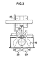
- Fig. 3 is a top view of the inventive device.
- Figs 1-3 show an embodiment of an inventive device 2 for sorting beverage containers, such as metal cans or plastic bottles (not shown), and subsequent compaction of packages complying with a certain, predetermined requirement profile and thus qualifying as accepted packages.
- the device 2 has an infeed unit 4, a checking unit 6 and a compacting unit 8, which will be described in more detail hereinbelow.
- a returned can or bottle is deposited in the infeed unit 4, which has a space with a substantially vertical opening 10' and a substantially horizontal opening 10", below which there is provided a tubular element 14 which is rotatable about a substantially horizontal shaft 12 and having an internal diameter which slightly exceeds the external diameter of ordinary recyclable beverage cans or bottles currently existing on the market.
- one end of the tubular element 14 substantially connects with the substantially horizontal opening 10" of the above-mentioned space.
- a first primary sorting is carried out of the objects to be deposited in the inventive device.
- a metal detector 15 of inductive or capacitive type is arranged at the tubular element 15. Such detectors are well-known in the art and, therefore, will not be described in more detail here.
- a dividable bottom plate 16 obstructing or exposing the upper end of the tubular element 14 for reasons which will be stated below.
- the plate 18 is driven by a drive unit 20, i.e. a motor, which drives the plate 18, either directly or via a transmission means, such as a belt.
- a drive unit 20 i.e. a motor, which drives the plate 18, either directly or via a transmission means, such as a belt.
- the plate 18 and the whole or parts of the drive unit 20 are suspended in pendulum fashion from a pin 22.
- a counterweight 24 is so adjusted as to balance the plate 18, the drive unit 20 and an aluminium can or plastic bottle accepted in accordance with the above-mentioned requirement profile, which is placed on the plate 18.
- a limit switch (not shown).
- the limit switch When an object not complying with the requirement profile by having an excessive weight is placed on the plate 18, this is pivoted downwards so as to actuate the limit switch, which in turn entails that the tubular element 14 is rotated to a first end position, in which it makes an angle of e.g. +45° with the vertical plane, thus passing the object on to e.g. an ejector.
- the plate 18 comprises a load cell for establishing the weight of the load placed on the plate.
- the processing of the above-mentioned signals nonetheless takes place in the aforementioned central control unit which is in the form of e.g. a microcomputer.
- the plate 18 preferably is rotary.
- the reason for this is that there is provided beside the plate 18 a bar-code reader 26, which also is connected to the above-mentioned microcomputer.
- the bar-code reader is used for identifying a bar code which is applied on the can or the bottle and which may contain information about manufacturing/recycling country, type of package, size of refund and so forth.
- the beverage container is deposited and passes through the tubular element 14, it will pass the metal detector 15 and land on the plate 18.
- the beverage container is turned by the rotating plate 18 past the reader 26 for establishing e.g. the type of package, i.e. whether the package is a metal can or a plastic bottle, the size of the refund etc., this information being stored in the microcomputer.
- the microcomputer activates the actuating means 28 and 30 which rotate the tubular element 14 through an angular range of +45° and -45°, respectively.
- the microcomputer activates the actuating means 28 and 30 which rotate the tubular element 14 through an angular range of +45° and -45°, respectively.
- deposited but rejected packages are conveyed e.g. to an ejector, which is achieved by the corresponding actuating means 28 causing the tubular element 14, partly surrounding the returned can, to rotate approximately +45° about the substantially horizontal shaft 12.
- the accepted package is moved onwards by actuation of the corresponding actuating means 30 so as to rotate the tubular element 14 through -45°, to the compacting unit 8.
- a shearing-type compacting unit essentially comprises a fixed rigid wall 32 and a wall 34 which is movable between substantially two end positions, in parallel with and towards the rigid wall 32, such that in a first end position it is located spaced from the rigid wall 32, the distance between the walls 32, 34 slightly exceeding the diameter of a can or bottle complying with the aforementioned requirement profile, while in a second end position it substantially makes contact with the rigid wall 32.
- the displacement of the movable wall 34 is brought about by an eccentric/lever mechanism, see especially Fig. 1.
- a disc 36 rotatably mounted in its centre, is driven by a motor 38.
- one revolution of the disc 36 corresponds to a compacting motion of the compacting unit 8.
- a contact means 50 actuable by the transmission arm 40 and one end 48 thereof.
- the contact means 50 can be actuated by direct contact, for example being a microswitch, or be e.g. of magnetic type.
- the signal from the contact means 50 is supplied to the aforementioned microcomputer which, responsive to this signal, controls the opening and the closure of the dividable bottom plate 16, so that more than one can or bottle is never passed on to the compacting unit 8.
- the other end of the lever 42 is displaced through a substantially quarter-circle-shaped path 44 when the transmission arm 40 is moved upwards.
- the movable wall 34 during its displacement is parallel to the fixed wall 32,.
- a can or bottle located between the walls, and possibly supported by a bottom pin 46, see Fig. 2 is compacted in a shear motion, i.e. is crushed substantially in the longitudinal direction. This shear motion requires considerably less energy and force than other known compacting techniques.
- the present invention is intended for use in a recycling machine for refund-type beverage containers complying with a certain requirement profile.
- the invention is especially well suited for use in a small-size compactor in local shops, filling stations, kiosks and the like.
- the paying-out unit necessary for printing out refund slips or for paying out the refund is suitably connected to the aforementioned microcomputer, which calculates the amount to be refunded. It is understood that a person skilled in the art may find alternative embodiments and other means which bring about the technical effect aimed at and which fall within the scope of the inventive concept. All such alterations and modifications are therefore intended to be encompassed by the claimed scope of protection.
Landscapes
- Engineering & Computer Science (AREA)
- Mechanical Engineering (AREA)
- Physics & Mathematics (AREA)
- General Physics & Mathematics (AREA)
- Auxiliary Devices For And Details Of Packaging Control (AREA)
- Basic Packing Technique (AREA)
- Sorting Of Articles (AREA)
- Processing Of Solid Wastes (AREA)
- Refuse Collection And Transfer (AREA)
- Container Filling Or Packaging Operations (AREA)
- Processing And Handling Of Plastics And Other Materials For Molding In General (AREA)
Claims (8)
- Dispositif pour le compactage de conditionnements recyclables tels que des bouteilles ou des boítes destinées à des boissons, qui comprend une unité d'alimentation (4), une unité de contrôle (6) et une unité de compactage (8), ladite unité de compactage (8) comprenant une paroi rigide fixe (32), une paroi rigide mobile (34) et un moyen pour déplacer la paroi mobile (34) en direction de la paroi fixe (32), lesdites parois (32, 34) étant essentiellement parallèles également au cours du déplacement de la paroi mobile (34) en direction de la paroi fixe (32), caractérisé en ce que la paroi mobile (34) effectue un mouvement en forme de quart de cercle, si bien que le conditionnement logé entre les parois (32, 34) est comprimé par un mouvement de cisaillement.
- Dispositif selon la revendication 1, caractérisé en ce que la distance maximale entre la paroi fixe (32) et la paroi mobile (34) est légèrement supérieure au diamètre d'une bouteille ou d'une boíte déposée, en respectant un profil requis.
- Dispositif selon la revendication 1 ou 2, caractérisé en ce que la paroi mobile (34) est déplacée au moyen d'un mécanisme de levier (42) dont une extrémité est reliée à la paroi mobile (34) et dont l'autre extrémité est reliée à une extrémité d'un bras de transmission (40) dont l'autre extrémité est reliée en mobilité à la région marginale d'un disque rotatif (36) de telle sorte qu'une révolution du disque rotatif (36) correspond à une course de l'unité de compactage (8).
- Dispositif selon la revendication 3, caractérisé en ce qu'un détecteur (50), lors du passage devant ce dernier de ladite autre extrémité du bras de transmission (40), génère un signal qui est acheminé à un moyen de commande qui, en réponse à ce signal, ouvre ou ferme une ouverture supérieure (16) pratiquée dans un élément tubulaire (14) dans l'unité d'alimentation (4).
- Dispositif selon la revendication 4, caractérisé en ce que ledit élément tubulaire (14) est essentiellement cylindrique et possède une extrémité opposée à l'unité d'alimentation (4), l'autre extrémité étant opposée à l'unité de contrôle (6), et en ce qu'il est relié à un moyen (12, 28; 30) pour déplacer l'élément tubulaire (14) entre différentes positions terminales en fonction des signaux (6) acheminés audit moyen de commande.
- Dispositif selon la revendication 5, caractérisé en ce que l'élément tubulaire (14) pivote en formant un angle d'environ +45° par rapport à la position terminale pour prendre une première position terminale dans laquelle des récipients rejetés destinés à des boissons sont déplacés jusqu'à un orifice d'éjection, et pivote en formant un angle d'environ -45° par rapport à la position initiale pour prendre une seconde position terminale dans laquelle les récipients acceptés destinés à des boissons sont déplacés vers l'unité de compactage (8).
- Dispositif selon l'une quelconque des revendications 1 à 6, caractérisé en ce que ladite unité de contrôle (6) comprend un détecteur de métaux (15) intégré dans l'élément tubulaire (14) s'étendant essentiellement en direction verticale, et un dynamomètre ou un contrepoids relié à une plaque (18) essentiellement horizontale pour détecter le poids d'un récipient destiné à des boissons disposé sur la plaque (18) et générant un signal qui est acheminé audit moyen de commande, ainsi qu'un lecteur de code-barres (26) disposé au-dessus de la plaque (18) et générant un signal qui est également acheminé audit moyen de commande.
- Dispositif selon la revendication 7, caractérisé en ce que ladite plaque (18) est montée en oscillation sur une broche (22) et, à une certaine déviation par rapport à une position normale essentiellement horizontale, agit sur un détecteur qui génère un signal en réponse à cette déviation.
Applications Claiming Priority (3)
| Application Number | Priority Date | Filing Date | Title |
|---|---|---|---|
| SE9300527A SE9300527D0 (sv) | 1993-02-17 | 1993-02-17 | Anordning foer sortering av metallburkar |
| SE9300527 | 1993-02-17 | ||
| PCT/SE1994/000131 WO1994019776A1 (fr) | 1993-02-17 | 1994-02-17 | Dispositif de compactage d'emballages consignes |
Publications (2)
| Publication Number | Publication Date |
|---|---|
| EP0685096A1 EP0685096A1 (fr) | 1995-12-06 |
| EP0685096B1 true EP0685096B1 (fr) | 1998-01-07 |
Family
ID=20388930
Family Applications (1)
| Application Number | Title | Priority Date | Filing Date |
|---|---|---|---|
| EP94907763A Expired - Lifetime EP0685096B1 (fr) | 1993-02-17 | 1994-02-17 | Dispositif de compactage d'emballages consignes |
Country Status (9)
| Country | Link |
|---|---|
| EP (1) | EP0685096B1 (fr) |
| AT (1) | ATE161991T1 (fr) |
| AU (1) | AU6120094A (fr) |
| DE (1) | DE69407761T2 (fr) |
| DK (1) | DK0685096T3 (fr) |
| FI (1) | FI116489B (fr) |
| NO (1) | NO953176L (fr) |
| SE (1) | SE9300527D0 (fr) |
| WO (1) | WO1994019776A1 (fr) |
Cited By (1)
| Publication number | Priority date | Publication date | Assignee | Title |
|---|---|---|---|---|
| US8606633B2 (en) | 2010-03-15 | 2013-12-10 | ReMag, LLC | Periodical recycling and reward distribution systems and methods |
Families Citing this family (3)
| Publication number | Priority date | Publication date | Assignee | Title |
|---|---|---|---|---|
| DE10132771A1 (de) * | 2001-07-11 | 2003-01-30 | Zentek Ges Fuer Kreislaufwirts | Vorrichtung und Verfahren zur Rücknahme von Gegenständen, insbesondere zur Rücknahme von Gebinden der Getränkeindustrie |
| DE10209504A1 (de) * | 2002-02-22 | 2003-09-18 | Rur Elektro Gmbh | Verfahren zum Sammeln von Pfandverpackungen, Preßvorrichtungen und Sammelbehältnis |
| GB2449213B (en) | 2007-05-18 | 2011-06-29 | Kraft Foods R & D Inc | Improvements in or relating to beverage preparation machines and beverage cartridges |
Family Cites Families (3)
| Publication number | Priority date | Publication date | Assignee | Title |
|---|---|---|---|---|
| US4519307A (en) * | 1983-12-08 | 1985-05-28 | Aluminum Company Of America | Container recycling apparatus using scanning means to read code markings on containers |
| FI903419A7 (fi) * | 1990-07-06 | 1992-01-07 | Halton Oy | Foerfarande och anordning vid sortering av returfoerpackningar av returflaskor, burkar m.m. |
| JPH05123898A (ja) * | 1991-05-27 | 1993-05-21 | Shizukou Kk | 缶処理機及び缶処理方法 |
-
1993
- 1993-02-17 SE SE9300527A patent/SE9300527D0/xx unknown
-
1994
- 1994-02-17 EP EP94907763A patent/EP0685096B1/fr not_active Expired - Lifetime
- 1994-02-17 WO PCT/SE1994/000131 patent/WO1994019776A1/fr not_active Ceased
- 1994-02-17 DE DE69407761T patent/DE69407761T2/de not_active Expired - Fee Related
- 1994-02-17 DK DK94907763T patent/DK0685096T3/da active
- 1994-02-17 AU AU61200/94A patent/AU6120094A/en not_active Abandoned
- 1994-02-17 AT AT94907763T patent/ATE161991T1/de not_active IP Right Cessation
-
1995
- 1995-08-14 NO NO953176A patent/NO953176L/no not_active Application Discontinuation
- 1995-08-16 FI FI953869A patent/FI116489B/fi active IP Right Grant
Cited By (1)
| Publication number | Priority date | Publication date | Assignee | Title |
|---|---|---|---|---|
| US8606633B2 (en) | 2010-03-15 | 2013-12-10 | ReMag, LLC | Periodical recycling and reward distribution systems and methods |
Also Published As
| Publication number | Publication date |
|---|---|
| FI953869A0 (fi) | 1995-08-16 |
| FI953869L (fi) | 1995-10-04 |
| ATE161991T1 (de) | 1998-01-15 |
| AU6120094A (en) | 1994-09-14 |
| DK0685096T3 (da) | 1998-09-07 |
| DE69407761T2 (de) | 1998-08-06 |
| NO953176L (no) | 1995-10-03 |
| FI116489B (fi) | 2005-11-30 |
| NO953176D0 (no) | 1995-08-14 |
| SE9300527D0 (sv) | 1993-02-17 |
| EP0685096A1 (fr) | 1995-12-06 |
| WO1994019776A1 (fr) | 1994-09-01 |
| DE69407761D1 (de) | 1998-02-12 |
Similar Documents
| Publication | Publication Date | Title |
|---|---|---|
| US4573641A (en) | Glass bottle collection and crushing apparatus | |
| US5361913A (en) | Reverse bottle vending, crushing and sorting machine | |
| US5355987A (en) | Single station reverse vending machine | |
| US5161661A (en) | Reverse vending apparatus having improved article rotating mechanism | |
| US5465822A (en) | Commodity densification assembly having a multiple path distribution device | |
| KR100946617B1 (ko) | 재활용 통합 분리수거 시스템 | |
| US4480737A (en) | Apparatus for recognizing, crushing separating, weighing and making payment for, used metal items, particularly aluminum cans | |
| US4492295A (en) | Automated redemption center for metal containers | |
| EP1947614B1 (fr) | Supports de convoyeur pour éléments consignés | |
| US5641039A (en) | Purchase checkout station | |
| EP0088182A2 (fr) | Appareil pour récupération des récipients aluminium et la restitution de la consigne | |
| US5152387A (en) | Reverse vending apparatus having improved article crushing mechanism | |
| US5630493A (en) | Acceptance assembly for a reverse vending machine | |
| US4257511A (en) | Method and apparatus for selective recovery of metal containers | |
| US5477953A (en) | Filter and filter cleaning system for a reverse vending machine | |
| KR102442789B1 (ko) | 재활용 수거장치 | |
| US4512253A (en) | Apparatus for processing recyclable containers | |
| US5988054A (en) | Automated system for handling returned drink containers | |
| CA1160196A (fr) | Dispositif de reconnaissance, compactage, separation, pesage et paiement pour metaux de rebut, notamment pour boites en aluminium | |
| US4472819A (en) | Can counter | |
| WO2011066839A1 (fr) | Système de distribution inverse pour enregistrement par lots de canettes usagées | |
| EP0685096B1 (fr) | Dispositif de compactage d'emballages consignes | |
| US4787495A (en) | Method and apparatus for selective scrap metal collection | |
| US4443697A (en) | System and method for selecting and segregating containers | |
| US5273150A (en) | Device for handling returnable cans |
Legal Events
| Date | Code | Title | Description |
|---|---|---|---|
| PUAI | Public reference made under article 153(3) epc to a published international application that has entered the european phase |
Free format text: ORIGINAL CODE: 0009012 |
|
| 17P | Request for examination filed |
Effective date: 19950814 |
|
| AK | Designated contracting states |
Kind code of ref document: A1 Designated state(s): AT BE CH DE DK ES FR GB GR IE IT LI LU MC NL PT SE |
|
| RAP1 | Party data changed (applicant data changed or rights of an application transferred) |
Owner name: SCANMATIC RECYCLING AB |
|
| RAP1 | Party data changed (applicant data changed or rights of an application transferred) |
Owner name: CANMATIC RECYCLING AB |
|
| GRAG | Despatch of communication of intention to grant |
Free format text: ORIGINAL CODE: EPIDOS AGRA |
|
| 17Q | First examination report despatched |
Effective date: 19970417 |
|
| GRAG | Despatch of communication of intention to grant |
Free format text: ORIGINAL CODE: EPIDOS AGRA |
|
| GRAH | Despatch of communication of intention to grant a patent |
Free format text: ORIGINAL CODE: EPIDOS IGRA |
|
| GRAH | Despatch of communication of intention to grant a patent |
Free format text: ORIGINAL CODE: EPIDOS IGRA |
|
| GRAA | (expected) grant |
Free format text: ORIGINAL CODE: 0009210 |
|
| AK | Designated contracting states |
Kind code of ref document: B1 Designated state(s): AT BE CH DE DK ES FR GB GR IE IT LI LU MC NL PT SE |
|
| PG25 | Lapsed in a contracting state [announced via postgrant information from national office to epo] |
Ref country code: NL Free format text: LAPSE BECAUSE OF FAILURE TO SUBMIT A TRANSLATION OF THE DESCRIPTION OR TO PAY THE FEE WITHIN THE PRESCRIBED TIME-LIMIT Effective date: 19980107 Ref country code: LI Free format text: LAPSE BECAUSE OF FAILURE TO SUBMIT A TRANSLATION OF THE DESCRIPTION OR TO PAY THE FEE WITHIN THE PRESCRIBED TIME-LIMIT Effective date: 19980107 Ref country code: IT Free format text: LAPSE BECAUSE OF FAILURE TO SUBMIT A TRANSLATION OF THE DESCRIPTION OR TO PAY THE FEE WITHIN THE PRE;WARNING: LAPSES OF ITALIAN PATENTS WITH EFFECTIVE DATE BEFORE 2007 MAY HAVE OCCURRED AT ANY TIME BEFORE 2007. THE CORRECT EFFECTIVE DATE MAY BE DIFFERENT FROM THE ONE RECORDED.SCRIBED TIME-LIMIT Effective date: 19980107 Ref country code: GR Free format text: LAPSE BECAUSE OF FAILURE TO SUBMIT A TRANSLATION OF THE DESCRIPTION OR TO PAY THE FEE WITHIN THE PRESCRIBED TIME-LIMIT Effective date: 19980107 Ref country code: FR Free format text: LAPSE BECAUSE OF FAILURE TO SUBMIT A TRANSLATION OF THE DESCRIPTION OR TO PAY THE FEE WITHIN THE PRESCRIBED TIME-LIMIT Effective date: 19980107 Ref country code: ES Free format text: THE PATENT HAS BEEN ANNULLED BY A DECISION OF A NATIONAL AUTHORITY Effective date: 19980107 Ref country code: CH Free format text: LAPSE BECAUSE OF FAILURE TO SUBMIT A TRANSLATION OF THE DESCRIPTION OR TO PAY THE FEE WITHIN THE PRESCRIBED TIME-LIMIT Effective date: 19980107 Ref country code: BE Free format text: LAPSE BECAUSE OF FAILURE TO SUBMIT A TRANSLATION OF THE DESCRIPTION OR TO PAY THE FEE WITHIN THE PRESCRIBED TIME-LIMIT Effective date: 19980107 Ref country code: AT Free format text: LAPSE BECAUSE OF FAILURE TO SUBMIT A TRANSLATION OF THE DESCRIPTION OR TO PAY THE FEE WITHIN THE PRESCRIBED TIME-LIMIT Effective date: 19980107 |
|
| REF | Corresponds to: |
Ref document number: 161991 Country of ref document: AT Date of ref document: 19980115 Kind code of ref document: T |
|
| REG | Reference to a national code |
Ref country code: CH Ref legal event code: EP |
|
| REF | Corresponds to: |
Ref document number: 69407761 Country of ref document: DE Date of ref document: 19980212 |
|
| PG25 | Lapsed in a contracting state [announced via postgrant information from national office to epo] |
Ref country code: LU Free format text: LAPSE BECAUSE OF NON-PAYMENT OF DUE FEES Effective date: 19980217 |
|
| PG25 | Lapsed in a contracting state [announced via postgrant information from national office to epo] |
Ref country code: IE Free format text: LAPSE BECAUSE OF NON-PAYMENT OF DUE FEES Effective date: 19980307 |
|
| PG25 | Lapsed in a contracting state [announced via postgrant information from national office to epo] |
Ref country code: PT Free format text: LAPSE BECAUSE OF FAILURE TO SUBMIT A TRANSLATION OF THE DESCRIPTION OR TO PAY THE FEE WITHIN THE PRESCRIBED TIME-LIMIT Effective date: 19980408 |
|
| NLV1 | Nl: lapsed or annulled due to failure to fulfill the requirements of art. 29p and 29m of the patents act | ||
| REG | Reference to a national code |
Ref country code: IE Ref legal event code: FG4D Free format text: 78256 |
|
| EN | Fr: translation not filed | ||
| REG | Reference to a national code |
Ref country code: CH Ref legal event code: PL |
|
| PG25 | Lapsed in a contracting state [announced via postgrant information from national office to epo] |
Ref country code: MC Free format text: LAPSE BECAUSE OF NON-PAYMENT OF DUE FEES Effective date: 19980831 |
|
| REG | Reference to a national code |
Ref country code: DK Ref legal event code: T3 |
|
| PLBE | No opposition filed within time limit |
Free format text: ORIGINAL CODE: 0009261 |
|
| STAA | Information on the status of an ep patent application or granted ep patent |
Free format text: STATUS: NO OPPOSITION FILED WITHIN TIME LIMIT |
|
| 26N | No opposition filed | ||
| PGFP | Annual fee paid to national office [announced via postgrant information from national office to epo] |
Ref country code: GB Payment date: 20010209 Year of fee payment: 8 |
|
| REG | Reference to a national code |
Ref country code: GB Ref legal event code: IF02 |
|
| PG25 | Lapsed in a contracting state [announced via postgrant information from national office to epo] |
Ref country code: GB Free format text: LAPSE BECAUSE OF NON-PAYMENT OF DUE FEES Effective date: 20020217 |
|
| GBPC | Gb: european patent ceased through non-payment of renewal fee |
Effective date: 20020217 |
|
| PGFP | Annual fee paid to national office [announced via postgrant information from national office to epo] |
Ref country code: DK Payment date: 20090213 Year of fee payment: 16 |
|
| PGFP | Annual fee paid to national office [announced via postgrant information from national office to epo] |
Ref country code: DE Payment date: 20090213 Year of fee payment: 16 |
|
| PGFP | Annual fee paid to national office [announced via postgrant information from national office to epo] |
Ref country code: SE Payment date: 20090206 Year of fee payment: 16 |
|
| REG | Reference to a national code |
Ref country code: DK Ref legal event code: EBP |
|
| EUG | Se: european patent has lapsed | ||
| PG25 | Lapsed in a contracting state [announced via postgrant information from national office to epo] |
Ref country code: DK Free format text: LAPSE BECAUSE OF NON-PAYMENT OF DUE FEES Effective date: 20100228 |
|
| PG25 | Lapsed in a contracting state [announced via postgrant information from national office to epo] |
Ref country code: DE Free format text: LAPSE BECAUSE OF NON-PAYMENT OF DUE FEES Effective date: 20100901 |
|
| PG25 | Lapsed in a contracting state [announced via postgrant information from national office to epo] |
Ref country code: SE Free format text: LAPSE BECAUSE OF NON-PAYMENT OF DUE FEES Effective date: 20100218 |