EP0685708A2 - Codeur à CD - Google Patents
Codeur à CD Download PDFInfo
- Publication number
- EP0685708A2 EP0685708A2 EP95302504A EP95302504A EP0685708A2 EP 0685708 A2 EP0685708 A2 EP 0685708A2 EP 95302504 A EP95302504 A EP 95302504A EP 95302504 A EP95302504 A EP 95302504A EP 0685708 A2 EP0685708 A2 EP 0685708A2
- Authority
- EP
- European Patent Office
- Prior art keywords
- encoder
- digitally encoded
- encoder according
- compact disk
- rotatable assembly
- Prior art date
- Legal status (The legal status is an assumption and is not a legal conclusion. Google has not performed a legal analysis and makes no representation as to the accuracy of the status listed.)
- Withdrawn
Links
Images
Classifications
-
- G—PHYSICS
- G01—MEASURING; TESTING
- G01D—MEASURING NOT SPECIALLY ADAPTED FOR A SPECIFIC VARIABLE; ARRANGEMENTS FOR MEASURING TWO OR MORE VARIABLES NOT COVERED IN A SINGLE OTHER SUBCLASS; TARIFF METERING APPARATUS; MEASURING OR TESTING NOT OTHERWISE PROVIDED FOR
- G01D5/00—Mechanical means for transferring the output of a sensing member; Means for converting the output of a sensing member to another variable where the form or nature of the sensing member does not constrain the means for converting; Transducers not specially adapted for a specific variable
- G01D5/26—Mechanical means for transferring the output of a sensing member; Means for converting the output of a sensing member to another variable where the form or nature of the sensing member does not constrain the means for converting; Transducers not specially adapted for a specific variable characterised by optical transfer means, i.e. using infrared, visible, or ultraviolet light
- G01D5/32—Mechanical means for transferring the output of a sensing member; Means for converting the output of a sensing member to another variable where the form or nature of the sensing member does not constrain the means for converting; Transducers not specially adapted for a specific variable characterised by optical transfer means, i.e. using infrared, visible, or ultraviolet light with attenuation or whole or partial obturation of beams of light
- G01D5/34—Mechanical means for transferring the output of a sensing member; Means for converting the output of a sensing member to another variable where the form or nature of the sensing member does not constrain the means for converting; Transducers not specially adapted for a specific variable characterised by optical transfer means, i.e. using infrared, visible, or ultraviolet light with attenuation or whole or partial obturation of beams of light the beams of light being detected by photocells
- G01D5/347—Mechanical means for transferring the output of a sensing member; Means for converting the output of a sensing member to another variable where the form or nature of the sensing member does not constrain the means for converting; Transducers not specially adapted for a specific variable characterised by optical transfer means, i.e. using infrared, visible, or ultraviolet light with attenuation or whole or partial obturation of beams of light the beams of light being detected by photocells using displacement encoding scales
- G01D5/3473—Circular or rotary encoders
Definitions
- the present invention relates to encoders in general and in particular to digital shaft encoders.
- Digital shaft encoders are used for providing position, direction, speed and displacement information of rotatable assemblies associated with devices ranging from low-tech consumer devices, for example, washing machines, to high-tech devices, for example, drum plotters, such as the Dolev, available from Scitex Ltd., Israel.
- Digital shaft encoders are basically of two types: absolute encoders for applications where position information is of prime importance and incremental encoders for applications where speed of rotation and/or incremental travel of the rotation assembly is of prime importance.
- Absolute encoders typically output unique codes for each position within a single revolution of a rotatable assembly and therefore any position within a single revolution can be determined without a starting address.
- Absolute encoders use either a brush assembly to make direct electrical contact with electrically conductive paths on a coded disk or a photo-electric assembly for reading opaque and transparent segments on a coded disk.
- Incremental encoders typically output pulse signals as a rotatable assembly rotates for providing travel, velocity and acceleration information.
- Incremental encoders typically include a disk having opaque lines which are aligned with a grid assembly such that light passing through the transparent parts of the disk are sensed by photosensors. The output from the photosensors is a sinusoidal wave which can be transformed into square-wave pulses for digital circuitry compatibility.
- a second track of opaque lines can be provided for determining the direction of rotation or for use as a home position indication.
- the conventional digital shaft encoders suffer from a number of disadvantages which include low resolution particularly for the absolute encoders and high cost for high resolution incremental encoders having gratings in the order of 36,000 lines.
- the main object of the present invention is to provide a low cost, high resolution digital shaft encoder which can be readily adapted as an absolute encoder and an incremental encoder.
- the encoder can provide position, direction, speed and displacement information depending on its implementation in both low-tech and high-tech devices.
- a digital shaft encoder for a rotatable assembly comprising: (a) a compact disk including digitally encoded information related to the angular position of the rotatable assembly, wherein the compact disk rotates in conjunction with the rotatable assembly; and (b) an optical pick-up for reading the digitally encoded information.
- the digitally encoded information on the compact disk can take one of several forms depending on whether the encoder is to be implemented as an absolute encoder, an incremental encoder or a combined absolute-incremental encoder.
- the optical pick-up can be rigidly mounted with respect to the compact disk regardless of the type of digitally encoded information provided thereon. The optical pick-up is typically deployed over the outermost track or the innermost track for ease of set-up of the encoder.
- the digitally encoded information can include a home position indication for marking a pre-determined home position of the rotatable assembly.
- the home position indication is typically digitally encoded as at least a portion of a frame and deployed on either the outermost or innermost track of the compact disc.
- the home position indication can be used for resetting the rotatable assembly to its home position or for counting the number of revolutions rotated by the rotatable assembly in an odometer-like fashion.
- the digitally encoded information can include a plurality of pulses for indicating incremental changes in position of the rotatable assembly.
- the pulses are typically digitally encoded as at least one bit and deployed on either the outermost track or innermost track of compact disc.
- the pulses can be used for indicating each incremental advance of the rotation assembly for determining travel displacement, angular velocity and acceleration in a tachometer-like fashion.
- the digitally encoded information can include two tracks of pulses characterized in that the tracks have a pulse phase relationship therebetween such that either clockwise or counter-clockwise rotation can be distinguished by means of the sign of the phase between the tracks.
- the digitally encoded information can include both the home position indication and pulses such that the encoder can act as a combined absolute-incremental encoder by providing a unique output of an angular position of the rotatable assembly from its home position in terms of the number of pulses from the home position indication.
- the digitally encoded information can include having all the frames of a track being given a unique code such that any position within a single revolution can be determined without a starting address.
- the present invention is of digital shaft encoders for providing position, direction, speed and displacement information of rotatable assemblies.
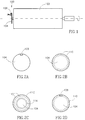
- Encoder 100 for providing information with respect to a rotatable assembly 102 associated with a device (not shown).
- Encoder 100 includes a compact disk 104 including digitally encoded information and an optical pick-up 106 for reading the digitally encoded information as known in the art.
- information about the position, direction, speed, acceleration and travel displacement of rotatable assembly 102 can be provided.
- Rotatable assembly 102 can be configured in a number of forms, including, but not limited to, a drum, a table, etc.
- Compact disk 104 within the context of the present invention refers to the type of disk initially popularized in sound reproduction systems. Salient features of compact disk technology relevant to the present invention are as follows. First, that the compact disks are 120 mm diameter disks capable of storing some 500-600 Mbytes of information in which pit/land or land/pit transitions represent "1"s while the flat areas of lands and pits represent "0"s. Second, that 8 real data bits are modulated into 14 channel bits by a method known as eight-to-fourteen modulation (EFM) and stored as frames consisting of 1 control byte, 24 data bytes and two groups of 4 error correction bytes.
- EFM eight-to-fourteen modulation
- optical pick-up 106 can be rigidly mounted with respect to compact disk 104 such that it reads typically only one track.
- Optical pick-up 106 is typically located to read either the innermost or the outermost track of compact disk 104 for ease of set-up of encoder 100 .
- the digitally encoded information on compact disk 104 can take one of several forms depending on whether encoder 100 is to be implemented as an absolute encoder, an incremental encoder or a combined absolute-incremental encoder.
- the digitally encoded information can include a home position indication 108 for marking a pre-determined home position of rotatable assembly 102 .
- Home position indication 108 is typically digitally encoded as at least a portion of a frame and deployed on either the outermost track or innermost track of compact disk 104 .
- Home position indication 108 can be used for resetting rotatable assembly 102 to its home position or for counting the number of revolutions rotated by rotatable assembly 102 in an odometer-like fashion.
- the digitally encoded information can include a plurality of pulses 110 for indicating incremental changes in position of rotatable assembly 102 .
- Pulses 110 are typically digitally encoded as at least one bit and deployed on either the outermost track or innermost track of compact disk 104 .
- Pulses 110 can be used for indicating each incremental advance of rotation assembly 102 , for counting its travel displacement and for determining its angular velocity and acceleration in a tachometer-like fashion.
- the digitally encoded information can include two tracks 112 and 114 of pulses 110 characterized in that they have a pulse phase relationship therebetween such that either clockwise or counter-clockwise rotation of rotation assembly 102 can be distinguished by means of the sign of the phase of pulses 110 read from tracks 112 and 114 .
- the digitally encoded information can include both home position indication 108 and pulses 110 such that encoder 100 can act as a combined absolute-incremental encoder by providing a unique output of an angular position of rotatable assembly 102 from its home position in terms of the number of pulses from home position indication 108 as counted by optical pick-up 106 .
- the digitally encoded information can include having all the frames of a track being given a unique code such that any position within a single revolution can be determined without a starting address.
- encoder 100 can be readily adapted for use with devices ranging from low-tech consumer items such as washing machines, dishwashers, etc. to high-tech items such as drum scanners.
- encoder 100 can be used to control the rpm of a drum while in a drum plotter, encoder 100 can be used for indicating to a controller the angular position of a drum.
Landscapes
- Physics & Mathematics (AREA)
- General Physics & Mathematics (AREA)
- Optical Transform (AREA)
Applications Claiming Priority (2)
| Application Number | Priority Date | Filing Date | Title |
|---|---|---|---|
| IL10986094A IL109860A0 (en) | 1994-06-01 | 1994-06-01 | Compact disc encoder |
| IL10986094 | 1994-06-01 |
Publications (2)
| Publication Number | Publication Date |
|---|---|
| EP0685708A2 true EP0685708A2 (fr) | 1995-12-06 |
| EP0685708A3 EP0685708A3 (fr) | 1996-02-07 |
Family
ID=11066194
Family Applications (1)
| Application Number | Title | Priority Date | Filing Date |
|---|---|---|---|
| EP95302504A Withdrawn EP0685708A3 (fr) | 1994-06-01 | 1995-04-13 | Codeur à CD. |
Country Status (2)
| Country | Link |
|---|---|
| EP (1) | EP0685708A3 (fr) |
| IL (1) | IL109860A0 (fr) |
Cited By (4)
| Publication number | Priority date | Publication date | Assignee | Title |
|---|---|---|---|---|
| WO2001096816A1 (fr) * | 2000-06-15 | 2001-12-20 | Scanlab Ag | Detecteur de position pour dispositif de balayage |
| GB2391301A (en) * | 2002-05-16 | 2004-02-04 | Graham Cyril Rumsey | Measurement of rotating objects using optical disk technology |
| EP1801546A1 (fr) | 2005-12-23 | 2007-06-27 | SICK STEGMANN GmbH | Support d'informations dans un codeur |
| EP3109600A1 (fr) | 2015-06-25 | 2016-12-28 | Vilniaus Gedimino technikos universitetas | Instrument de mesure pour l'angle de rotation d'un objet, procédé de production correspondant, et son application |
Family Cites Families (4)
| Publication number | Priority date | Publication date | Assignee | Title |
|---|---|---|---|---|
| DE68906290T2 (de) * | 1988-02-22 | 1993-09-23 | Victor Company Of Japan | Detektorsystem mit einem optischen rotierenden kodierer zur feststellung der verschiebung einer beweglichen vorrichtung. |
| US5006703A (en) * | 1988-02-22 | 1991-04-09 | Victor Company Of Japan, Ltd. | Reflective optical rotary encoder disc |
| US5107107A (en) * | 1990-03-30 | 1992-04-21 | The United States Of America As Represented By The Administarator Of The National Aeronautics And Space Administration | Laser optical disk position encoder with active heads |
| DE4025055B4 (de) * | 1990-08-07 | 2004-06-03 | Base Ten Systems Electronics Gmbh | Positionsauslesevorrichtung, insbesondere für Maschinen- und Drehtisch-Steuerungen |
-
1994
- 1994-06-01 IL IL10986094A patent/IL109860A0/xx unknown
-
1995
- 1995-04-13 EP EP95302504A patent/EP0685708A3/fr not_active Withdrawn
Cited By (6)
| Publication number | Priority date | Publication date | Assignee | Title |
|---|---|---|---|---|
| WO2001096816A1 (fr) * | 2000-06-15 | 2001-12-20 | Scanlab Ag | Detecteur de position pour dispositif de balayage |
| US6921893B1 (en) | 2000-06-15 | 2005-07-26 | Scanlab Ag | Position detector for a scanning device |
| GB2391301A (en) * | 2002-05-16 | 2004-02-04 | Graham Cyril Rumsey | Measurement of rotating objects using optical disk technology |
| EP1801546A1 (fr) | 2005-12-23 | 2007-06-27 | SICK STEGMANN GmbH | Support d'informations dans un codeur |
| US7718952B2 (en) | 2005-12-23 | 2010-05-18 | Sick Stegmann Gmbh | Information carrier |
| EP3109600A1 (fr) | 2015-06-25 | 2016-12-28 | Vilniaus Gedimino technikos universitetas | Instrument de mesure pour l'angle de rotation d'un objet, procédé de production correspondant, et son application |
Also Published As
| Publication number | Publication date |
|---|---|
| IL109860A0 (en) | 1994-10-07 |
| EP0685708A3 (fr) | 1996-02-07 |
Similar Documents
| Publication | Publication Date | Title |
|---|---|---|
| US4935917A (en) | Memory disk having some capacity recording areas on a spiral track | |
| US4734901A (en) | Recording and reproducing apparatus | |
| KR890005213B1 (ko) | 광디스크장치 | |
| JP2591742B2 (ja) | コンパクトデイスク駆動装置 | |
| US4907215A (en) | Integral optical recording of product code in data areas | |
| KR960042525A (ko) | 데이타 기록/재생장치 및 방법과, 데이타 기록 매체 | |
| JPS59901B2 (ja) | デイスク記憶装置 | |
| JP2002513923A (ja) | 多回転エンコーダ | |
| CN1047159A (zh) | 信息记录系统及其使用的记录器和记录载体 | |
| JPH0357541B2 (fr) | ||
| KR890005722A (ko) | 정보기록 및 판독 시스템 | |
| EP0685708A2 (fr) | Codeur à CD | |
| CN1276596A (zh) | 光盘记录方法和装置、光盘及光盘再现装置 | |
| US5285440A (en) | Magneto-optic disk | |
| EP0440091B1 (fr) | Procédé d'enregistrement et reproduction de disques et appareil de reproduction | |
| JPS59180867A (ja) | レ−ベル表示装置 | |
| JP3001149B2 (ja) | エンコーダ | |
| US5877623A (en) | Method for measuring recording linear velocity of data on compact disk | |
| CN113566855A (zh) | 编码盘、编码器、电机及编码器工作方法 | |
| JP2803860B2 (ja) | 光ディスク | |
| JPH0283880A (ja) | デイスク情報記録・読取り方法 | |
| JP3237677B2 (ja) | エラー訂正用符号の形成方法 | |
| CN1776812A (zh) | 光学可刻写型碟形记录载体 | |
| JPS6242364A (ja) | 回転同期マ−ク検出装置 | |
| KR100300971B1 (ko) | 광디스크의 회전 속도 설정방법 |
Legal Events
| Date | Code | Title | Description |
|---|---|---|---|
| PUAI | Public reference made under article 153(3) epc to a published international application that has entered the european phase |
Free format text: ORIGINAL CODE: 0009012 |
|
| AK | Designated contracting states |
Kind code of ref document: A2 Designated state(s): DE FR GB IT |
|
| PUAL | Search report despatched |
Free format text: ORIGINAL CODE: 0009013 |
|
| AK | Designated contracting states |
Kind code of ref document: A3 Designated state(s): DE FR GB IT |
|
| STAA | Information on the status of an ep patent application or granted ep patent |
Free format text: STATUS: THE APPLICATION IS DEEMED TO BE WITHDRAWN |
|
| 18D | Application deemed to be withdrawn |
Effective date: 19960808 |