EP0685728B1 - Photoakustisches Analysegerät - Google Patents
Photoakustisches Analysegerät Download PDFInfo
- Publication number
- EP0685728B1 EP0685728B1 EP94810332A EP94810332A EP0685728B1 EP 0685728 B1 EP0685728 B1 EP 0685728B1 EP 94810332 A EP94810332 A EP 94810332A EP 94810332 A EP94810332 A EP 94810332A EP 0685728 B1 EP0685728 B1 EP 0685728B1
- Authority
- EP
- European Patent Office
- Prior art keywords
- chamber
- light
- measuring chamber
- reference chamber
- enclosure
- Prior art date
- Legal status (The legal status is an assumption and is not a legal conclusion. Google has not performed a legal analysis and makes no representation as to the accuracy of the status listed.)
- Expired - Lifetime
Links
- 239000000463 material Substances 0.000 claims description 10
- 238000005259 measurement Methods 0.000 claims description 6
- 239000012530 fluid Substances 0.000 claims description 4
- 238000004458 analytical method Methods 0.000 claims description 3
- 230000003287 optical effect Effects 0.000 claims 1
- 241000894007 species Species 0.000 description 17
- 238000010586 diagram Methods 0.000 description 9
- 239000007789 gas Substances 0.000 description 9
- CBENFWSGALASAD-UHFFFAOYSA-N Ozone Chemical compound [O-][O+]=O CBENFWSGALASAD-UHFFFAOYSA-N 0.000 description 6
- 230000005855 radiation Effects 0.000 description 6
- 239000000126 substance Substances 0.000 description 6
- 238000000034 method Methods 0.000 description 4
- 238000010521 absorption reaction Methods 0.000 description 3
- 238000010276 construction Methods 0.000 description 3
- 239000000203 mixture Substances 0.000 description 3
- 238000012545 processing Methods 0.000 description 3
- ATUOYWHBWRKTHZ-UHFFFAOYSA-N Propane Chemical compound CCC ATUOYWHBWRKTHZ-UHFFFAOYSA-N 0.000 description 2
- 229910052782 aluminium Inorganic materials 0.000 description 2
- XAGFODPZIPBFFR-UHFFFAOYSA-N aluminium Chemical compound [Al] XAGFODPZIPBFFR-UHFFFAOYSA-N 0.000 description 2
- 230000003749 cleanliness Effects 0.000 description 2
- 239000000470 constituent Substances 0.000 description 2
- 230000003247 decreasing effect Effects 0.000 description 2
- 230000001419 dependent effect Effects 0.000 description 2
- 238000001514 detection method Methods 0.000 description 2
- 230000005284 excitation Effects 0.000 description 2
- 238000012544 monitoring process Methods 0.000 description 2
- 239000002245 particle Substances 0.000 description 2
- 238000001228 spectrum Methods 0.000 description 2
- 229910001220 stainless steel Inorganic materials 0.000 description 2
- 239000010935 stainless steel Substances 0.000 description 2
- PFNQVRZLDWYSCW-UHFFFAOYSA-N (fluoren-9-ylideneamino) n-naphthalen-1-ylcarbamate Chemical compound C12=CC=CC=C2C2=CC=CC=C2C1=NOC(=O)NC1=CC=CC2=CC=CC=C12 PFNQVRZLDWYSCW-UHFFFAOYSA-N 0.000 description 1
- IBOFVQJTBBUKMU-UHFFFAOYSA-N 4,4'-methylene-bis-(2-chloroaniline) Chemical compound C1=C(Cl)C(N)=CC=C1CC1=CC=C(N)C(Cl)=C1 IBOFVQJTBBUKMU-UHFFFAOYSA-N 0.000 description 1
- JBRZTFJDHDCESZ-UHFFFAOYSA-N AsGa Chemical compound [As]#[Ga] JBRZTFJDHDCESZ-UHFFFAOYSA-N 0.000 description 1
- VGGSQFUCUMXWEO-UHFFFAOYSA-N Ethene Chemical compound C=C VGGSQFUCUMXWEO-UHFFFAOYSA-N 0.000 description 1
- 239000005977 Ethylene Substances 0.000 description 1
- 229910001218 Gallium arsenide Inorganic materials 0.000 description 1
- 241001112258 Moca Species 0.000 description 1
- 150000001335 aliphatic alkanes Chemical class 0.000 description 1
- 230000005540 biological transmission Effects 0.000 description 1
- 238000001816 cooling Methods 0.000 description 1
- 238000005260 corrosion Methods 0.000 description 1
- 230000007797 corrosion Effects 0.000 description 1
- 238000000354 decomposition reaction Methods 0.000 description 1
- 238000013461 design Methods 0.000 description 1
- 238000007599 discharging Methods 0.000 description 1
- 230000005670 electromagnetic radiation Effects 0.000 description 1
- 229910052732 germanium Inorganic materials 0.000 description 1
- GNPVGFCGXDBREM-UHFFFAOYSA-N germanium atom Chemical compound [Ge] GNPVGFCGXDBREM-UHFFFAOYSA-N 0.000 description 1
- 239000012535 impurity Substances 0.000 description 1
- 239000011261 inert gas Substances 0.000 description 1
- 238000003780 insertion Methods 0.000 description 1
- 230000037431 insertion Effects 0.000 description 1
- 238000009413 insulation Methods 0.000 description 1
- 239000012212 insulator Substances 0.000 description 1
- 230000003993 interaction Effects 0.000 description 1
- 229910052743 krypton Inorganic materials 0.000 description 1
- DNNSSWSSYDEUBZ-UHFFFAOYSA-N krypton atom Chemical compound [Kr] DNNSSWSSYDEUBZ-UHFFFAOYSA-N 0.000 description 1
- 229910052751 metal Inorganic materials 0.000 description 1
- 239000002184 metal Substances 0.000 description 1
- 238000012986 modification Methods 0.000 description 1
- 230000004048 modification Effects 0.000 description 1
- 229920000642 polymer Polymers 0.000 description 1
- -1 propane Chemical class 0.000 description 1
- 239000001294 propane Substances 0.000 description 1
- 238000004445 quantitative analysis Methods 0.000 description 1
- 238000011160 research Methods 0.000 description 1
- 230000035945 sensitivity Effects 0.000 description 1
- 239000007787 solid Substances 0.000 description 1
- 239000000758 substrate Substances 0.000 description 1
- 229920001059 synthetic polymer Polymers 0.000 description 1
- 238000012546 transfer Methods 0.000 description 1
- 238000013022 venting Methods 0.000 description 1
Images


Classifications
-
- G—PHYSICS
- G01—MEASURING; TESTING
- G01N—INVESTIGATING OR ANALYSING MATERIALS BY DETERMINING THEIR CHEMICAL OR PHYSICAL PROPERTIES
- G01N21/00—Investigating or analysing materials by the use of optical means, i.e. using sub-millimetre waves, infrared, visible or ultraviolet light
- G01N21/17—Systems in which incident light is modified in accordance with the properties of the material investigated
- G01N21/1702—Systems in which incident light is modified in accordance with the properties of the material investigated with opto-acoustic detection, e.g. for gases or analysing solids
Definitions
- This invention generally relates to the art of analyzing fluids and specifically to photoacoustic devices for quantitative analysis of fluids, normally in a gaseous state.
- the principle common to known photoacoustic devices and methods is interaction of light, generally in the infrared portion of the electromagnetic spectrum, with a gaseous sample containing a known analytic species of interest - which may but need not be an impurity - in an unknown concentration for generating a sonic signal dependent upon the concentration of the species of interest.
- Anal. Chem., vol.54, n°9. August 1982. pg. 1485-1489 discloses a photoacoustic device and a method for detection of NO 2 in air samples at a total pressure of about 1 bar using a continuous-wave krypton laser generating a visible pulsating beam of light. and being suitable for passing two cylindrical sample cells of identical design and construction.
- the device includes a measuring cell filled with NO 2 in mixture with air. and a reference cell filled with air only. Both cells are in an essentially linear arrangement.
- Various types of condenser micro-phones for detection of the photoacoustic signal are tested because of corrosion problems.
- DE 33 45 077 discloses a photoacoustic device and a method for measuring the concentration of a gas in a mixture of gases or of solid particles in a gas using a cell having a gas inlet and a gas outlet for receiving and discharging a gas. and means for directing laser beam from a source into the cell.
- a chopper is arranged in the path of the laser beam between the device and the cell to generate a frequency corresponding to the resonance frequency of the cell.
- a microphone is used for detecting the acoustic signal generated by changes of the pressure within the cell. The concentration of the gas. or the concentration of the particles in the gas, is determined from the acoustic signal.
- an analytic species of interest is considered “unstable” if it will or may decompose under the conditions of measurement. Conversely, an analytic species of interest is considered to be “stable” if it does not decompose to a significant degree under the conditions of measurement.
- a photoacoustic device for analysis of fluids comprising:
- the measuring chamber or chambers has (have) inlet and outlet means or ports, such as conduits and valves, for passing a gaseous medium containing the known species of interest in an unknown concentration into and out of the measuring chamber;
- the reference chamber(s) and the measuring chamber(s) each contain a sound detector, such as a microphone or other transducer capable of converting sound within the frequency range generated by the pulsating beam, into an electric signal in relation to the sound.
- the reference chamber(s) contain(s) a gaseous medium suitable for serving as a photoacoustic reference for the gaseous medium containing the species of interest.
- the gaseous medium in the reference chamber preferably contains the same constituents as the gaseous medium in the measuring chamber.
- the reference chamber preferably contains an essentially stable or inert gaseous medium that is suitable as a photoacoustic reference; such suitability or compatibility for use as a reference is understood in the photoacoustic art and is based upon similarity or compatibility of absorption, e.g similar absorption in the same infrared frequency band.
- various and normally gaseous organic substances such as alkanes, e.g. propane, are suitable for use in the reference chamber when ozone is the species of interest.
- Conventional electronic signal processors can be used to amplify and/or convert the output signal of the sound detectors or microphones into the desired units of measurement, e.g. parts per million, percents, weight units per volume, units of partial pressure, or the like.
- a part or all of the electronic signal processing means could be integrated into the analyzer according to the invention but this is not generally preferred because one and the same processor can be used in combination with a number of analytic devices for use in detecting specific species of interest and, hence, including different gaseous media in the reference chamber(s).
- the rate of decay of the chemically reactive substance may be used for calibration of said analytic device.
- rate of decay can be determined under laboratory conditions for a given configuration of the device according to the invention and used under field conditions for calibrating the instrument.
- the analytic system 1 shown diagrammatically in Fig. 1 comprises a cell 11 having a measuring chamber 111 and a reference chamber 112 in linear or serial arrangement according to the invention.
- a source 12 of a pulsating, i.e. modulated, beam of light comprises a light source 122, e.g. an incandescent lamp or another emitter of electromagnetic radiation in the infrared region typically in the range of from about 3 • 10 11 to about 3.8 • 10 14 Hz.
- a filter (not shown in Fig. 1) may be used to select a specific range dependent in a manner known per se upon the gaseous medium under consideration.
- a frequency band having a high efficiency of transfer of light energy into thermal energy for the specific gaseous medium will be selected in a manner known per se in the photoacoustic art.
- An optional photodetector 13 may be provided for synchronization purposes and/or for monitoring the pulse frequency, and a power supply line 126 for light source 122 as well as a signal line 131 of detector 13 will be provided for operation.
- a bell 123 e.g. of an essentially tubular configuration, having at least one perforation or opening 124 is connected to a drive 121, e.g. an electric motor.
- a drive 121 e.g. an electric motor.
- a modulated beam of light pulsating at a predetermined rate e.g. 10 Hz, will be produced by the emitter or source 12.
- the pulsating beam passes through an optional filter (not shown in Fig. 1) through a window 116 into reference chamber 112 and through a second window 115 into measuring chamber 111.
- Cell 11 is arranged within an enclosure (not shown in Fig. 1) in a manner explained in more detail below.
- Windows 115, 116 are made of a material that permits passage of infrared radiation. Such materials (also termed electroacoustic substrates) are known in the art, e.g. as referenced above, and include such substances as zinc selenide, gallium arsenide, and germanium.
- Each chamber 111 and 112 is provided with a sound detector 113, 114, e.g. microphones. These detectors can be in physical contact with the cell but should not normally be in such contact with the enclosure; accordingly, a sonic shielding (not shown in Fig. 1) can be used for external sonic protection of the detectors 113,114.
- Measuring chamber 111 is connected with an inlet conduit 141 that can be opened and closed by a valve 14 which is connected with a source of the gas containing the analytic species of interest, optionally via pump 18.
- Chamber 11 is also connected with an outlet conduit 151 with associated valve 15 and a venting line 16.
- both valves are automated valves for control via lines 171, 172.
- the output signal S of detector 113 as well as the reference signal R are fed into a conventional signal processing and control unit 19; such units are available commercially, e.g. under the trade name MOCA, analyzer model 3610, from Orbisphere Laboratories, Neucal, Switzerland.
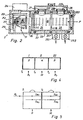
- Fig. 2 is a semi-diagrammatic sectional view of a preferred embodiment of a photoacoustic device 2 according to the invention. It comprises a source 21 of a pulsating beam B of light emanating from an emitter 211, e.g. an incandescent lamp combined with a paraboloid reflector 212 or other paralleling means supported by bracket 215, within enclosure means 22.
- a rotatable bell 213 provided with an opening 216 is connected to motor 214 and is operated in the manner explained above in connection with Fig.1.
- source 21 should be capable of providing a black-body spectrum.
- a detector (not shown in Fig. 2) can be used for monitoring and/or synchronization purposes as explained above.
- Enclosure means 22 serves to integrally connect source 21 of the pulsating beam with cell 23.
- a number of sonic insulators 223, e.g. cushions, sonic blocks or O-rings made of an elastomeric polymer serve to hold cell 23 suspended within enclosure 22, preferably in an essentially coaxial manner with regard to the longitudinal axis of enclosure 22 for simplicity of construction.
- enclosure 22 is of relatively heavy construction, e.g. with a wall thickness in the range of from about 5 - 15 mm, and is made of a relatively "heavy" (i. e. having the capacity of absorbing sonic energy) structural material, such as stainless steel.
- Cell 23 does not need heavy walling and can be made of a light structural metal, such as aluminum, an optionally reinforced synthetic polymer composition or the like.
- An optional filter 26 is provided at the beam entrance end of reference chamber 24 and is made of a material that is selectively transparent to the infrared radiation selected for the particular device 2 considering the nature of the gaseous media within chambers 24 and 25. Selection of a proper filter is known in the photoacoustic art.
- windows 241 near the entrance end of chamber 24 as well as window 254 between chambers 24 and 25 are made of a material that is transparent for infrared radiation but need not be selective.
- measuring chamber 25 can be provided with a mirror (not shown in Fig. 2) for infrared radiation.
- Inlet 251 including a valve and outlet 252, also including a valve, are provided for supplying measuring chamber 25 with a gaseous medium containing the (known) species of interest in an unknown concentration.
- Sonic detectors 27, 28, e.g. microphones of the type known for use in photoacoustics, are provided to detect sonic frequencies produced by the gaseous media in chambers 24, 25 upon the impact of pulsating beam B and the thermal excitation of the gaseous media, or their constituents of interest, produced thereby.
- Signal lines (not shown in Fig. 2) are provided for connection with a signal processing device as explained above.
- enclosure 22 constitutes an integral device which provides a path P for beam B through reference chamber 24 and measuring chamber 25.
- sonic detectors 27, 28 are connected with cell 23 but do not mechanically contact enclosure 22 because of openings 227 and 228 provided in enclosure 22.
- a sonic shield 229 is provided for acoustic protection of detectors 27, 28 against external noise and can be evacuated if desired via an opening 226.
- the inner space of enclosure 22 insofar as not occupied by cell 23 and detectors 27, 28 can be evacuated, maintained under reduced pressure and/or filled with an inert gas. It is to be noted that the device illustrated herein can be said to be of the non-resonant type.
- Fig. 3 is a perspective and semi-diagrammatic view of a preferred embodiment of the pulse generator or "chopper” 3.
- the term “chopper” normally refers to such devices as are used on the top of emergency vehicles emitting flashes of colored light and the structure of such devices is of use in the invention.
- Upper wall 31 is made of a heavy disk, e.g. of stainless steel, which may have a number of equally distanced openings 321 for air cooling of the light source.
- Tubular side wall 32 should be made of a very light and thin material that is not transparent for infrared radiation, e.g. aluminum, in order to minimize the impact of imbalance caused by the absence of wall material in opening 321.
- the opening can be covered with a material that is transparent to infrared radiation and has a mass that is similar to that of an equally dimensioned segment of the material of side wall 32. It is to be noted that side edges of opening 321 can be straight as shown or rounded, depending upon the desired configuration of the light pulses.
- the linear or serial arrangement of reference and measurement chambers in the cell of a device according to the invention vary in essentially the same way in dependence upon external parameters, such as temperature, impact of vibration, extraneous noise etc.
- Fig. 4 shows the diagram of a cell having three chambers, e.g. a first reference chamber I, a first measuring chamber II and an additional chamber III which could be either a reference chamber or a measuring chamber. If chamber III is a second reference cell, such arrangement permits to check the operation of the reference cells as well as the cleanliness of the entrance window of the measuring cell.
- T 1 , T 2 , T 3 indicate the transmission coefficients for mathematical treatment of operation.
- ⁇ and ⁇ indicate the absorption in the particular chamber.
- Fig. 5 is a diagram of a cell in which the pulses P 0 pass through reference chamber R as well as through measuring chamber M, and are reflected at the end of measuring chamber M by means of a mirror (not indicated in Fig. 5).
- Mathematical treatment of the values of reference signals S R1 , S R2 and of measuring signals S M1 , S M2 indicates that information about the cleanliness of the entrance window of measuring chamber M can be obtained by calculating coefficient T 2 .
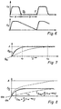
- Fig. 6 shows two superimposed diagrams in which the ordinate of the upper diagram indicates the light signal L S ; the ordinate of the lower diagram indicates the strength of the acoustic signal A S while the abscissa of both diagrams indicates the chopper cycle T. It can be shown that the acoustic signal optimally is zero when the excitation cycle starts.
- Parameter a/b depends upon the frequency of modulation at ⁇ 100 Hz. For example, an value for a/b of 0.44 can be obtained for a chopper window of 110°.
- Fig. 7 shows a diagram for signal slopes ⁇ 11 and ⁇ 12 ; the ordinate indicates the strength of the acoustic signal A while the abscissa indicates the concentration of the species of analytical interest, e.g. ozone.
- Mathematical analysis indicates that if the cell length is decreased for a given acoustic signal, the measurable concentration range will increase.
Landscapes
- Physics & Mathematics (AREA)
- Health & Medical Sciences (AREA)
- Life Sciences & Earth Sciences (AREA)
- Chemical & Material Sciences (AREA)
- Analytical Chemistry (AREA)
- Biochemistry (AREA)
- General Health & Medical Sciences (AREA)
- General Physics & Mathematics (AREA)
- Immunology (AREA)
- Pathology (AREA)
- Investigating Or Analysing Materials By Optical Means (AREA)
- Investigating Or Analyzing Materials By The Use Of Ultrasonic Waves (AREA)
- Optical Measuring Cells (AREA)
Claims (10)
- Photo-akustisches Analysegerät (2) für Fluide, mit(A) einer Quelle (21) für einen pulsierenden Lichtstrahl und(B) einem Behältnis (22), das seinerseits:dadurch gekennzeichnet, dassmindestens eine Referenzkammer (24) und mindestens eine Messkammer (25) innerhalb des Behältnisses enthält; wobei
- (B-1)
- das Behältnis dem pulsierenden Lichtstrahl einen Pfad P durch mindestens eine Referenzkammer und durch mindestens eine Messkammer bietet; wobei mindestens eine Messkammer Mittel für Einlass (251) und für Auslass (252) eines gasförmigen Mediums besitzt, um die zu messende Komponente in unbekannter Konzentration in die Messkammer ein- und aus der Messkammer abzuführen;
- (B-2)
- die mindestens eine Referenzkammer und die mindestens eine Messkammer je einen Detektor (27, 28) für Töne aufweist, die vom pulsierenden Lichtstrahl in der mindestens einen Referenzkammer und der mindestens einen Messkammer erzeugt worden sind; wobei beide Tondetektoren Signale im Verhältnis zur Intensität der Töne erzeugen können; und
- (B-3)
- die mindestens eine Referenzkammer ein gasförmiges Medium enthält, welches als photo-akustische Referenz für das gasförmige Medium mit der zu messenden Komponente dient;
der pulsierende Lichtstrahl zuerst mindestens eine Referenzkammer (24) und erst danach mindestens eine Messkammer passiert; und
die Referenzkammer (24) und die Messkammer (25) sich beide in einer gemeinsamen Zelle (23) innerhalb des Behältnisses (22) befinden. - Analysegerät nach Anspruch 1, das ferner Mittel (19) zur Auswertung der Signale aufweist, die jeweils von einem der Tondetektoren (113, 114) im Verhältnis zu der unbekannten Konzentration der zu messenden Komponente erzeugt worden sind.
- Analysegerät nach Anspruch 1 oder 2, wobei die Quelle (12) des pulsierenden Lichtstrahls eine Lichtquelle (122), die Licht im infraroten Bereich emittieren kann und einen Zerhacker (121, 123, 124) aufweist, der die Lichtquelle umschliesst und einen drehbaren Schild (123) mit einem Antrieb (121) besitzt, der den Schild mit einer voreingestellten Drehgeschwindigkeit rotieren lassen kann, wobei der Schild eine Öffnung (121) aufweist, um eine Modulation der Lichtquelle auf eine Frequenz zu bewirken, welche der voreingestellten Drehgeschwindigkeit entspricht.
- Analysegerät nach einem der Ansprüche 1 - 3, wobei zwischen der Quelle (12) des pulsierenden Lichtstrahls und der Messkammer (111) mindestens eine Referenzkammer (112) angebracht ist.
- Analysegerät nach einem der Ansprüche 1 - 4, wobei die mindestens eine Referenzkammer (24) ein erstes Fenster (241) für den Einlass des pulsierenden Lichtstrahls und ein zweites Fenster (254) für den Übergang des pulsierenden Lichtstrahls aus der Referenzkammer in die Messkammer (25) besitzt und wobei sowohl das erste als auch das zweite aus einem für infrarotes Licht durchlässigen, jedoch für das gasförmige Medium in der Referenzkammer im wesentlichen undurchlässigen Material hergestellt ist.
- Analysegerät nach einem der Ansprüche 1 - 5, das in einer linearen Anordnung und in dieser Reihenfolge eine erste Referenzkammer (R1) umfasst, die mindestens eine Messkammer (M) und eine zweite Referenzkammer (R2) besitzt, wobei die Messkammer ein Fenster für den Übergang von infrarotem Licht in die zweite Referenzkammer hat.
- Analysegerät nach einem der Ansprüche 1 - 6, wobei das Behältnis (22) eine im wesentlichen längliche zylindrische äussere Form aufweist, die gemeinsame Zelle (23) ebenfalls eine im wesentlichen längliche zylindrische äussere Form hat und im wesentlichen koaxial mit dem sie umschliessenden Behältnis angeordnet ist.
- Analysegerät nach einem der Ansprüche 3 - 7, wobei zwischen der Lichtquelle (21) und dem ersten Fenster (241) ein optisches Filter (26) angebracht ist.
- Analysegerät nach einem der Ansprüche 1 - 8, wobei die Zelle (23) mittels akustischer Dämpfungselemente (223) im Behältnis (22) in Position gehalten wird.
- Analysegerät nach einem der Ansprüche 1 - 9, wobei die Tondetektoren (227, 228) in physischem Kontakt mit der Zelle (23) stehen, aber keinen physischen Kontakt mit dem Behältnis (22) haben; und wobei sich ein akustischer Schild (229) auf dem Behältnis befindet, um die Tondetektoren vor unbeabsichtigten akustischen Einflüssen abzuschirmen.
Priority Applications (4)
| Application Number | Priority Date | Filing Date | Title |
|---|---|---|---|
| EP94810332A EP0685728B1 (de) | 1994-06-04 | 1994-06-04 | Photoakustisches Analysegerät |
| DE69431873T DE69431873T2 (de) | 1994-06-04 | 1994-06-04 | Photoakustisches Analysegerät |
| US08/443,533 US5616826A (en) | 1994-06-04 | 1995-05-18 | Photoacoustic analyzer and method |
| JP13821095A JP3627112B2 (ja) | 1994-06-04 | 1995-06-05 | 光音響分析装置及び分析方法 |
Applications Claiming Priority (1)
| Application Number | Priority Date | Filing Date | Title |
|---|---|---|---|
| EP94810332A EP0685728B1 (de) | 1994-06-04 | 1994-06-04 | Photoakustisches Analysegerät |
Publications (2)
| Publication Number | Publication Date |
|---|---|
| EP0685728A1 EP0685728A1 (de) | 1995-12-06 |
| EP0685728B1 true EP0685728B1 (de) | 2002-12-11 |
Family
ID=8218266
Family Applications (1)
| Application Number | Title | Priority Date | Filing Date |
|---|---|---|---|
| EP94810332A Expired - Lifetime EP0685728B1 (de) | 1994-06-04 | 1994-06-04 | Photoakustisches Analysegerät |
Country Status (4)
| Country | Link |
|---|---|
| US (1) | US5616826A (de) |
| EP (1) | EP0685728B1 (de) |
| JP (1) | JP3627112B2 (de) |
| DE (1) | DE69431873T2 (de) |
Families Citing this family (47)
| Publication number | Priority date | Publication date | Assignee | Title |
|---|---|---|---|---|
| NO300346B1 (no) * | 1995-04-05 | 1997-05-12 | Sinvent As | Foto-akustisk måleanordning |
| ES2221925T3 (es) * | 1995-09-04 | 2005-01-16 | Siemens Building Technologies Ag | Sensor de gas fotoacustico y su utilizacion. |
| NO963924A (no) * | 1996-09-19 | 1997-12-15 | Nyfotek As | Foto-akustisk infrarød detektor |
| EP0840105A1 (de) | 1996-11-05 | 1998-05-06 | Orbisphere Laboratories Neuchatel Sa | Verfahren und Vorrichtung zur Spektroskopie |
| DE59712692D1 (de) * | 1997-01-25 | 2006-08-24 | Siemens Schweiz Ag | Optoakustischer Gassensor |
| US5780724A (en) * | 1997-03-27 | 1998-07-14 | United Technologies Corp | Photo-acoustic leak detector with improved signal-to-noise response |
| US5852308A (en) * | 1997-06-30 | 1998-12-22 | Honeywell Inc. | Micromachined inferential opto-thermal gas sensor |
| US6039055A (en) * | 1998-01-08 | 2000-03-21 | International Business Machines Corporation | Wafer cleaning with dissolved gas concentration control |
| WO1999044040A1 (en) * | 1998-02-26 | 1999-09-02 | Presens As | A method for drift compensated measurement of gas concentration, and a photoacoustical gas sensor |
| US6154307A (en) * | 1998-09-18 | 2000-11-28 | United Technologies Corporation | Method and apparatus to diffract multiple beams |
| US6089076A (en) * | 1998-09-18 | 2000-07-18 | United Technologies Corporation | System to control the power of a beam |
| US6244101B1 (en) * | 1999-06-01 | 2001-06-12 | Battelle Memorial Institute | Photoacoustic method for measuring concentration of chemical species |
| US6612306B1 (en) | 1999-10-13 | 2003-09-02 | Healthetech, Inc. | Respiratory nitric oxide meter |
| WO2001046669A2 (en) * | 1999-10-25 | 2001-06-28 | Interwoven Technologies Corporation | System and method for characterizing and identifying agents |
| DK173775B1 (da) * | 2000-01-14 | 2001-10-08 | Pas Technology As | Gasanalysator |
| US7034943B1 (en) * | 2000-03-03 | 2006-04-25 | Aritron Intrumente AG | Gas sensors |
| US6408681B1 (en) * | 2000-03-23 | 2002-06-25 | The United States Of America As Represented By The Secretary Of The Army | Single particle photoacoustic absorption spectrometer |
| AU2001296456A1 (en) | 2000-09-29 | 2002-04-08 | Healthetech, Inc. | Indirect calorimetry system |
| US6662627B2 (en) * | 2001-06-22 | 2003-12-16 | Desert Research Institute | Photoacoustic instrument for measuring particles in a gas |
| US7064329B2 (en) * | 2001-08-21 | 2006-06-20 | Franalytica, Inc. | Amplifier-enhanced optical analysis system and method |
| HU225660B1 (en) * | 2002-05-24 | 2007-05-29 | Mol Magyar Olaj & Gazipari Rt | Method for photoacoustic measurement of concentration of non hydrocarbon component of gas mixture containing methane |
| AU2002344910A1 (en) * | 2002-07-12 | 2004-02-02 | Abb Research Ltd | High-resolution absorption spectrometer and corresponding measuring method |
| AU2002344911A1 (en) * | 2002-07-12 | 2004-02-02 | Abb Research Ltd | Absorption spectrometer and corresponding measuring method |
| EP1797478A4 (de) * | 2004-10-04 | 2009-07-15 | Univ South Carolina | Multivariate optische berechnung thermaler selektivität |
| US8325343B2 (en) * | 2010-02-16 | 2012-12-04 | Honeywell International Inc. | Detector for cavity ring-down spectroscopy |
| US8695402B2 (en) * | 2010-06-03 | 2014-04-15 | Honeywell International Inc. | Integrated IR source and acoustic detector for photoacoustic gas sensor |
| US8434366B2 (en) | 2010-12-15 | 2013-05-07 | Texas Instruments Incorporated | Active detection techniques for photoacoustic sensors |
| US8701465B2 (en) * | 2011-04-28 | 2014-04-22 | Honeywell International Inc. | Photoacoustic sensor diffusion membrane attachment structure |
| US9380981B2 (en) | 2013-03-15 | 2016-07-05 | Covidien Lp | Photoacoustic monitoring technique with noise reduction |
| GB201312046D0 (en) * | 2013-07-04 | 2013-08-21 | Sonex Metrology Ltd | An acoustic isolation chamber |
| US9570659B2 (en) * | 2013-10-14 | 2017-02-14 | Infineon Technologies Ag | Semiconductor device for emitting frequency-adjusted infrared light |
| US9513261B2 (en) * | 2013-10-14 | 2016-12-06 | Infineon Technologies Ag | Photoacoustic gas sensor device and a method for analyzing gas |
| EP3265766B1 (de) | 2015-03-05 | 2023-09-27 | Honeywell International Inc. | Verwendung ausgewählter glastypen und glasdicken im optischen pfad zur beseitigung von querempfindlichkeit auf wasserabsorptionsspitzen |
| DE202015002315U1 (de) * | 2015-03-27 | 2015-05-06 | Infineon Technologies Ag | Gassensor |
| US10859536B2 (en) | 2015-04-02 | 2020-12-08 | The Curators Of The University Of Missouri | Photoacoustic flow cell for identification of rare analytes in suspension |
| DE102015106373B4 (de) | 2015-04-24 | 2023-03-02 | Infineon Technologies Ag | Photoakustisches gassensormodul mit lichtemittereinheit und einer detektoreinheit |
| US20180299369A1 (en) | 2015-09-10 | 2018-10-18 | Honeywell International Inc. | Gas detector with normalized response and improved sensitivity |
| EP3359933A1 (de) | 2015-10-09 | 2018-08-15 | Honeywell International Inc. | Detektor für elektromagnetische strahlung mit einer planaren golay-zelle |
| DE102016103646B4 (de) * | 2016-01-22 | 2023-03-02 | Infineon Technologies Ag | Integriertes photoakustisches gassensormodul |
| US10302599B2 (en) * | 2016-10-27 | 2019-05-28 | Infineon Technologies Ag | Photoacoustic gas detector |
| US10466174B2 (en) * | 2016-12-13 | 2019-11-05 | Infineon Technologies Ag | Gas analyzer including a radiation source comprising a black-body radiator with at least one through-hole and a collimator |
| US10620165B2 (en) * | 2016-12-29 | 2020-04-14 | Infineon Technologies Ag | Photoacoustic gas analyzer for determining species concentrations using intensity modulation |
| CN107817219A (zh) * | 2017-12-05 | 2018-03-20 | 北京国网富达科技发展有限责任公司 | 一种双级增强型光声光谱检测器装置及其检测方法 |
| EP3561487B1 (de) * | 2018-04-25 | 2023-01-18 | ABB Schweiz AG | Messvorrichtung zur analyse einer zusammensetzung eines brenngases mit einer vor einem detektor angeordneten filterkammer |
| KR102005486B1 (ko) * | 2018-10-23 | 2019-07-30 | 한국수력원자력 주식회사 | 신뢰성이 향상된 유중 가스 분석 광음향 장치 |
| DE102021117510A1 (de) * | 2021-07-07 | 2023-01-12 | FR Vermögensverwaltung GbR Vertretungsberechtigte Gesellschafter: Franziska Michl, Kirchsteig 44, 95679 Waldershof /Raimund Hoffmann, Beethovenstraße 20, 95632 Wunsiedel | Analysevorrichtung und Verfahren zur Bestimmung eines Schwingungsmusters einer Substanz |
| CN116930091B (zh) * | 2023-09-14 | 2023-12-12 | 武汉理通微芬科技有限公司 | 基于非共振光声池的气体分析装置 |
Family Cites Families (21)
| Publication number | Priority date | Publication date | Assignee | Title |
|---|---|---|---|---|
| US2106612A (en) * | 1935-08-06 | 1938-01-25 | Gen Electric | Straightener for woven material |
| SU116724A1 (ru) * | 1956-05-14 | 1957-11-30 | П.И. Бреслер | Газоанализатор |
| SU449286A1 (ru) * | 1972-05-29 | 1974-11-05 | Специальное Конструкторско-Технологическое Бюро Медицинских И Физиологических Приборов | Оптико-акустический газоанализатор |
| US3820901A (en) * | 1973-03-06 | 1974-06-28 | Bell Telephone Labor Inc | Measurement of concentrations of components of a gaseous mixture |
| US3948345A (en) * | 1973-06-15 | 1976-04-06 | Allan Rosencwaig | Methods and means for analyzing substances |
| US3938365A (en) * | 1973-11-29 | 1976-02-17 | Massachusetts Institute Of Technology | Detecting trace gaseous species acoustically in response to radiation from an intense light source |
| DE2508637C3 (de) * | 1975-02-28 | 1979-11-22 | Max-Planck-Gesellschaft Zur Foerderung Der Wissenschaften E.V., 3400 Goettingen | Anordnung zur optischen Messung von Blutgasen |
| US4027972A (en) * | 1976-03-31 | 1977-06-07 | Andros Incorporated | Gas analyzer method and apparatus |
| US4163382A (en) * | 1978-04-28 | 1979-08-07 | The United States Of America As Represented By The United States Department Of Energy | Method and apparatus for optoacoustic spectroscopy |
| GB2059574A (en) * | 1979-06-25 | 1981-04-23 | Thermo Electron Corp | Absorption cell gas monitor |
| JPS595939A (ja) * | 1982-07-03 | 1984-01-12 | Horiba Ltd | パ−テイキユレ−ト連続測定装置 |
| JPS5994027A (ja) * | 1982-11-20 | 1984-05-30 | Horiba Ltd | 光音響効果型測定装置 |
| US5030420A (en) * | 1982-12-23 | 1991-07-09 | University Of Virginia Alumni Patents Foundation | Apparatus for oxygen determination |
| JPS59145957A (ja) * | 1983-01-08 | 1984-08-21 | Horiba Ltd | 光音響型濃度測定装置 |
| US4622845A (en) * | 1985-03-21 | 1986-11-18 | Westinghouse Electric Corp. | Method and apparatus for the detection and measurement of gases |
| DE3617763A1 (de) * | 1985-05-28 | 1986-12-04 | Olympus Optical Co., Ltd., Tokio/Tokyo | Verfahren zur durchfuehrung immunologischer bestimmungen und dafuer geeignete vorrichtung |
| IL77494A (en) * | 1986-01-01 | 1989-12-15 | Irad Technologies Ltd | Gas analyzer |
| DK247786D0 (da) * | 1986-05-27 | 1986-05-27 | Brueel & Kjaer As | Fotoakustisk gasanalysator |
| DK160590C (da) * | 1988-09-12 | 1991-09-16 | Fls Airloq As | Fremgangsmaade til detektering af en gasart ved hjaelp af fotoakustisk spektroskopi |
| US5003488A (en) * | 1989-03-10 | 1991-03-26 | Gespac, Inc. | Automatic fluid sedimentation rate measurement apparatus and method |
| DE4034375A1 (de) * | 1990-10-29 | 1992-04-30 | Diehl Gmbh & Co | Gas-messeinrichtung |
-
1994
- 1994-06-04 EP EP94810332A patent/EP0685728B1/de not_active Expired - Lifetime
- 1994-06-04 DE DE69431873T patent/DE69431873T2/de not_active Expired - Fee Related
-
1995
- 1995-05-18 US US08/443,533 patent/US5616826A/en not_active Expired - Fee Related
- 1995-06-05 JP JP13821095A patent/JP3627112B2/ja not_active Expired - Fee Related
Also Published As
| Publication number | Publication date |
|---|---|
| EP0685728A1 (de) | 1995-12-06 |
| JP3627112B2 (ja) | 2005-03-09 |
| DE69431873D1 (de) | 2003-01-23 |
| US5616826A (en) | 1997-04-01 |
| DE69431873T2 (de) | 2003-11-13 |
| JPH07333139A (ja) | 1995-12-22 |
Similar Documents
| Publication | Publication Date | Title |
|---|---|---|
| US5616826A (en) | Photoacoustic analyzer and method | |
| CN101213438B (zh) | 光声光谱仪设备 | |
| CN101458234B (zh) | 便携式电力变压器故障诊断仪 | |
| US4594004A (en) | Continuous particulate-measuring apparatus using an optoacoustic effect | |
| US5341214A (en) | NDIR gas analysis using spectral ratioing technique | |
| Adams et al. | Analytical optoacoustic spectrometry. Part I. Instrument assembly and performance characteristics | |
| Kamm | Detection of weakly absorbing gases using a resonant optoacoustic method | |
| CN1302276C (zh) | 一种光学气体鉴别系统 | |
| EP0195685A2 (de) | Verfahren und Vorrichtung zum Nachweis und zur Messung von Gasen | |
| Adams | Real-time in situ measurements of atmospheric optical absorption in the visible via photoacoustic spectroscopy. 1: Evaluation of photoacoustic cells | |
| JPH05503352A (ja) | 赤外線を用いたガス検出器 | |
| CN112924388B (zh) | 正交双通道声学谐振装置 | |
| CA2738820C (en) | An arrangement adapted for spectral analysis of high concentrations of gas | |
| JP5022363B2 (ja) | 光音響検出器及び光音響検出方法 | |
| US3899252A (en) | Ndir gas analyzer based on absorption modulation ratios for known and unknown samples | |
| EP0518993B1 (de) | Verfahren und gerät zur übertragung eines akustischen signals in einer photoakustischen zelle | |
| GB2358245A (en) | Photo-acoustic gas sensor | |
| JPS6238345A (ja) | 固形粒子の分析方法及び装置 | |
| CA1122432A (en) | Resonant subcavity differential spectrophone | |
| US3920993A (en) | Piggyback optical bench | |
| CN113267453A (zh) | 无源音叉共振增强的全光纤三气体探测光声光谱系统及其探测方法 | |
| CN218412261U (zh) | 基于紫外双波长关联光谱法的硫化氢气体检测装置 | |
| EP0924508A2 (de) | Vorrichtung und Verfahren zum Messen von Lichtabsorption | |
| Fisher et al. | Frequency analysis of pulsed optoacoustic signals and the application to chemical analysis | |
| Tam | Signal enhancement and noise suppression considerations in photothermal spectroscopy |
Legal Events
| Date | Code | Title | Description |
|---|---|---|---|
| PUAI | Public reference made under article 153(3) epc to a published international application that has entered the european phase |
Free format text: ORIGINAL CODE: 0009012 |
|
| AK | Designated contracting states |
Kind code of ref document: A1 Designated state(s): CH DE FR GB LI |
|
| 17P | Request for examination filed |
Effective date: 19951120 |
|
| RBV | Designated contracting states (corrected) |
Designated state(s): CH DE FR GB LI |
|
| 17Q | First examination report despatched |
Effective date: 20020125 |
|
| GRAG | Despatch of communication of intention to grant |
Free format text: ORIGINAL CODE: EPIDOS AGRA |
|
| GRAG | Despatch of communication of intention to grant |
Free format text: ORIGINAL CODE: EPIDOS AGRA |
|
| GRAH | Despatch of communication of intention to grant a patent |
Free format text: ORIGINAL CODE: EPIDOS IGRA |
|
| RTI1 | Title (correction) |
Free format text: PHOTOACOUSTIC ANALYZER |
|
| GRAH | Despatch of communication of intention to grant a patent |
Free format text: ORIGINAL CODE: EPIDOS IGRA |
|
| GRAA | (expected) grant |
Free format text: ORIGINAL CODE: 0009210 |
|
| AK | Designated contracting states |
Kind code of ref document: B1 Designated state(s): CH DE FR GB LI |
|
| REG | Reference to a national code |
Ref country code: GB Ref legal event code: FG4D |
|
| REG | Reference to a national code |
Ref country code: CH Ref legal event code: EP |
|
| REF | Corresponds to: |
Ref document number: 69431873 Country of ref document: DE Date of ref document: 20030123 |
|
| REG | Reference to a national code |
Ref country code: CH Ref legal event code: NV Representative=s name: RITSCHER & PARTNER AG PATENTANWAELTE |
|
| ET | Fr: translation filed | ||
| PLBE | No opposition filed within time limit |
Free format text: ORIGINAL CODE: 0009261 |
|
| STAA | Information on the status of an ep patent application or granted ep patent |
Free format text: STATUS: NO OPPOSITION FILED WITHIN TIME LIMIT |
|
| 26N | No opposition filed |
Effective date: 20030912 |
|
| REG | Reference to a national code |
Ref country code: CH Ref legal event code: PCAR Free format text: RITSCHER & PARTNER AG;RESIRAIN 1;8125 ZOLLIKERBERG (CH) |
|
| PGFP | Annual fee paid to national office [announced via postgrant information from national office to epo] |
Ref country code: CH Payment date: 20080619 Year of fee payment: 15 |
|
| PGFP | Annual fee paid to national office [announced via postgrant information from national office to epo] |
Ref country code: DE Payment date: 20080626 Year of fee payment: 15 |
|
| PGFP | Annual fee paid to national office [announced via postgrant information from national office to epo] |
Ref country code: FR Payment date: 20080529 Year of fee payment: 15 |
|
| PGFP | Annual fee paid to national office [announced via postgrant information from national office to epo] |
Ref country code: GB Payment date: 20080611 Year of fee payment: 15 |
|
| REG | Reference to a national code |
Ref country code: CH Ref legal event code: PL |
|
| GBPC | Gb: european patent ceased through non-payment of renewal fee |
Effective date: 20090604 |
|
| REG | Reference to a national code |
Ref country code: FR Ref legal event code: ST Effective date: 20100226 |
|
| PG25 | Lapsed in a contracting state [announced via postgrant information from national office to epo] |
Ref country code: LI Free format text: LAPSE BECAUSE OF NON-PAYMENT OF DUE FEES Effective date: 20090630 Ref country code: FR Free format text: LAPSE BECAUSE OF NON-PAYMENT OF DUE FEES Effective date: 20090630 Ref country code: CH Free format text: LAPSE BECAUSE OF NON-PAYMENT OF DUE FEES Effective date: 20090630 |
|
| PG25 | Lapsed in a contracting state [announced via postgrant information from national office to epo] |
Ref country code: GB Free format text: LAPSE BECAUSE OF NON-PAYMENT OF DUE FEES Effective date: 20090604 |
|
| PG25 | Lapsed in a contracting state [announced via postgrant information from national office to epo] |
Ref country code: DE Free format text: LAPSE BECAUSE OF NON-PAYMENT OF DUE FEES Effective date: 20100101 |