EP0685841A2 - Nachgiebige Plattenspeicheranordnung für ein Aufnahme/Wiedergabegerät - Google Patents
Nachgiebige Plattenspeicheranordnung für ein Aufnahme/Wiedergabegerät Download PDFInfo
- Publication number
- EP0685841A2 EP0685841A2 EP95103512A EP95103512A EP0685841A2 EP 0685841 A2 EP0685841 A2 EP 0685841A2 EP 95103512 A EP95103512 A EP 95103512A EP 95103512 A EP95103512 A EP 95103512A EP 0685841 A2 EP0685841 A2 EP 0685841A2
- Authority
- EP
- European Patent Office
- Prior art keywords
- cylindrical body
- memory disk
- support ring
- memory
- disk
- Prior art date
- Legal status (The legal status is an assumption and is not a legal conclusion. Google has not performed a legal analysis and makes no representation as to the accuracy of the status listed.)
- Withdrawn
Links
Images


Classifications
-
- G—PHYSICS
- G11—INFORMATION STORAGE
- G11B—INFORMATION STORAGE BASED ON RELATIVE MOVEMENT BETWEEN RECORD CARRIER AND TRANSDUCER
- G11B17/00—Guiding record carriers not specifically of filamentary or web form, or of supports therefor
- G11B17/02—Details
- G11B17/038—Centering or locking of a plurality of discs in a single cartridge
-
- G—PHYSICS
- G11—INFORMATION STORAGE
- G11B—INFORMATION STORAGE BASED ON RELATIVE MOVEMENT BETWEEN RECORD CARRIER AND TRANSDUCER
- G11B25/00—Apparatus characterised by the shape of record carrier employed but not specific to the method of recording or reproducing, e.g. dictating apparatus; Combinations of such apparatus
- G11B25/04—Apparatus characterised by the shape of record carrier employed but not specific to the method of recording or reproducing, e.g. dictating apparatus; Combinations of such apparatus using flat record carriers, e.g. disc, card
- G11B25/043—Apparatus characterised by the shape of record carrier employed but not specific to the method of recording or reproducing, e.g. dictating apparatus; Combinations of such apparatus using flat record carriers, e.g. disc, card using rotating discs
Definitions
- This invention relates generally to recording/reproducing devices, such as hard disk drives and particularly to a memory disk assembly therefore for minimizing unwanted memory disk motion induced by the motor drive system, or power train, of the memory disk assembly.
- the disk(s) are conventionally hard mounted to a hub, as seen in Figs. 1 and 2, of U.S. Patent 3,587,074 to A. M. Angle et al; or to a motor rotor as seen in Fig. 1, the prior art, of U.S. Patent 4,945,432 to T. Matsudaira et al, and Fig. 1 of U.S. Patent 4,965,476 to J. G. Lin.
- the motion of the power train which drives the memory disk or disks induces unwanted disk motion which adversely affects the read/write function of the head/disk assembly.
- the thrust of the teachings of Matsudaira et al, as to their invention, is to provide an axially compliant mount for fragile disks in a disk stack so that the "--magnetic disks 1 are protected against extraordinarily large forces caused by the difference in thermal expansion of different components. Thus, the disks are not deformed and do not break.” (column 4, lines 31-33 of Matsudaira et al).
- Matsudaira et al in Fig. 2, for example, illustrate a disk assembly, such as an assembly of ceramic or glass disks, in a disk stack on the hub of a motor rotor.
- the disks in the disk stack are spaced apart by elastic spacers and clamped in a stack between a shoulder 10 at the bottom of the motor hub or spindle and a clamp secured at the upper end of the motor hub.
- a hard disk pack 3 comprising a memory disk support ring 3a, functioning both as a disk mount and a disk spacer ring, is provided with coaxial, flat, annular, axial surfaces, 3b, 3c, to which the hard memory disks, 3d, 3e, are adhesively bonded.
- the adhesive bonding is the sole support of the hard memory disks, 3d, 3e, in the hard disk pack 3.
- Inner annular coaxial surfaces, 3f, 3g, of the memory disk support ring 3a of the hard disk pack 3, provide hard mounting surfaces for the memory disk support ring 3a of the hard disk pack 3, on a cylindrical section 5a of the motor rotor 5 which powers the disk pack 3.
- the disk pack 3, as used here, may comprise only one disk 3d, but the requirement of a hard flat mount for warp-free mounting of that single disk 3d remains.
- the disk support ring 3a of the hard disk pack 3 provides a sturdy mount for attachment to the cylindrical section 5a of the motor rotor 5.
- the inner annular axial surfaces, 3f, 3g, of the disk support ring 3a are subject to clamping pressure between a shoulder 5b on the cylindrical section 5a on the motor rotor, and a clamp 5c at the end of the cylindrical section 5a, there is no distortion of the disk support ring 3a of the disk pack 3 at least, in the region where the disks are bonded, to distort or warp the disks, 3d, 3e, bonded thereto.
- a memory disk assembly for minimizing unwanted disk motion in a memory disk assembly, comprises a hard disk pack which is compliantly mounted to the power train of the memory disk assembly.
- the power train includes the motor of the memory disk assembly and any part of the motor such as the motor rotor or a motor shaft, which is connected to the hard disk pack.
- the compliant hard disk pack mount is also referred to herein as a "soft" mount, the soft mount comprising a material having elasticity and a "memory" of position, form or shape to which it returns after a displacement, with minimum or no hysteresis.
- the power train comprises a rotatable hub or rotor which has a cylindrical body having a cylinder axis about which the hub or rotor rotates.
- the hard disk pack comprises a memory disk support ring which has a hard, flat, annular, axial face concentrically disposed about a central circular opening and at least one memory disk which has a central circular opening of greater diameter than the circular opening in the memory disk support ring.
- the memory disk is concentrically secured, as by adhesive bonding, to the axial surface of the memory disk support ring to form the hard disk pack.
- the cylindrical body of the rotatable hub is fitted through the central circular opening of the memory disk support ring of the hard disk pack, in which position the memory disk support ring of the hard disk pack is mounted, as by elastomeric attachment, to the cylindrical body of the rotatable hub to provide a compliant, hard disk pack mount.
- the attenuation of unwanted power train mechanical energy and resulting isolation of the unwanted power train energy from the hard disk pack reduces unwanted disk motion sufficiently to permit higher density disk track recording with the same power train in the same storage volume.
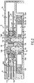
- Fig. 2 is a sectional view of a small form factor (1.3 form factor, for example) hard disk drive, seen as a sectional view of the memory disk assembly taken in a section plane which includes the spin axis of the memory disk assembly.
- Fig. 2 is drawn to an enlarged scale and
- Fig. 3 is a further enlargement of a fragmentary portion of Fig. 2, to provide enlargement of the illustration of essential detail.
- the hard disk drive 6 is not shown in its entirety in the interest of simplicity, the invention residing in the hard memory disk assembly.
- the mainframe or support structure 7 of metal such as aluminum, is the primary structural member of the disk drive 6.
- a cover 7e is bonded to the mainframe 7 to seal and encloses the disk drive therewithin.
- the hard disk drive further comprises a hard memory disk assembly 8 and a rotary actuator assembly 9.
- the rotary actuator assembly 9 is only fragmentarily shown at the left of Fig. 2. Both the rotary actuator assembly 9 and the hard disk assembly 8 are mounted upon the mainframe 7.
- the rotary actuator 9 is conventionally journaled (not shown) on the mainframe 7 and comprises four load beams 9a in an armstack, one load beam above and one load beam below each hard disk, 11a, 11b, of a hard disk pack 11 of the hard disk assembly 8. Each load beam 9a mounts a magnetic head 9d4 adjacent its distal end.
- An actuator motor (not shown) conventionally powers the rotary actuator.
- the hard memory disk assembly 8 which is the subject of this invention, is described below.
- the hard memory disk assembly 8 includes a power train which comprises a salient pole, direct current disk motor 10, which has a salient pole stator 12 and an umbrella shaped, disk motor rotor 13.
- the disk motor rotor 13 comprises a cylindrical body 13a having an end face 13c and a central, axial motor shaft 13b projecting therefrom.
- the mainframe or support 7 supports a tubular motor mount 7a which projects from the support 7.
- the tubular motor mount 7a is an integral part of the support 7.
- the tubular motor mount 7a is provided with an enlarged diameter cylindrical section 7b at its bottom end defining an external shoulder 7c.
- the salient pole stator 12 is a laminated assembly of thin plates of magnetic material, comprising a circular center section 12a and individual, radially disposed, salient poles 12b radiating therefrom.
- the circular center section 12a of the salient pole stator 12 seats upon and is adhesively bonded to, the shoulder 7c.
- Individual coils or windings 12d are respectively mounted on each salient pole 12b.
- the salient poles 12b are cantilevered from the circular center section 12a of the salient pole stator 12.
- the disk motor rotor 13 is of a magnetic flux conducting material configured of cylindrical sections of several different diameters, increasing in diameter from the top of the motor rotor to its bottom.
- the cylindrical body 13a of the motor rotor 13 terminates in a shoulder 13g, Fig. 3.
- a depending peripheral rim 13a4 of the motor rotor 13 mounts an annular, permanent ring 13f which is secured, as by adhesive bonding, to the inner circumferential surface of the depending rim 13a4, in a position encircling the pole tips 12c of the salient poles 12b, defining radial gaps therebetween.
- the annular permanent magnet 13f is radially magnetized in equally circumferentially spaced positions to form discrete permanent magnet poles different in number from the number of salient poles 12b. Energization of the windings 12d for constant speed motor operation is conventional.
- the hard disk pack 11 comprises a stack of two hard disks, 11a, 11b, of non-metallic material such as ceramic material or glass. Metal such as aluminum may also be employed.
- Each hard memory disk, 11a, 11b has a central circular opening, 11a1, 11b1.
- Each hard memory disk is adhesively bonded to the opposite annular axial surfaces, 11d1, 11d2 of the memory disk support ring 11d.
- the memory disk support ring, 11d has a central circular opening 11e which is a slip fit over the cylindrical body 13a of the motor rotor 13. This central circular opening 11e is of smaller diameter than the central circular openings 11a1, 11b1, in the hard memory disks, 11a, 11b, defining an inner annular flange 11f.
- This inner annular flange 11f is captured on the cylindrical body 13a of the motor rotor 13 between a shoulder 13g on the cylindrical body 13a and a clamp 13h, secured by a screw 13i at the top of the cylindrical body 13a. This screw 13i threads into the upper end of the motor shaft 13b.
- Elastomeric toroids 11f such as O-rings, on opposite sides of the inner annular flange 11f, are compressed in the stack between the shoulder 13g and the peripheral rim 13g1 of the clamp 13h, to secure the inner annular flange 11f of the memory disk support ring 11d in the compliant grip of the elastomeric toroids 13j, whereby radial or angular slippage of the disk pack with respect to the cylindrical body 13a is prevented.
- this compliant mounting of the hard disk pack 11 to the cylindrical body 13a is achieved without any clamping pressure being applied to the memory disks 11a or 11b.
- the hard disk pack 11 is a separate integrated entity. Compliant clamping forces of the elastomeric toroids 11j act solely upon the internal annular flange 11f of the memory disk support ring 11d.
- the hard disk pack 11 is an integrated disk stack which is easily assembled and is easily installed and removed with respect to the cylindrical body 13a, as a unitary assembly, by removing the clamp 13h after the magnetic heads 9d4 are moved clear of the disks 11a, 11b..
- the elastomeric toroids 11j are under compression.
- Tests of this soft, or compliant mount were conducted in comparison with the hard mount of Fig. 1 at 10% compression and 20% compression of the diameter of the toroids 11j. In all cases, the clamping forces were sufficient to obviate relative displacement radially or angularly between the cylindrical body 13a and the hard memory disk pack 11, due to slippage at the points of engagement.
- Attenuation of unwanted power train energy and motion was generally more effective at the 10% level of elastomeric toroid compression than at the 20% level.
- the type of disk drive used in the tests had a hard disk pack 11 of two hard disks and a rotary actuator 9 with an armstack of four arms 9a, each arm mounting a transducer 9d4, one transducer for each disk surface.
- the transducers, or magnetic heads, as well as the hard disks, were numbered 0, 1, 2, 3, from top to bottom in the armstack. Tests were conducted with respect to all of the heads 9d4.
- Test results are shown in Figs. 6 and 7, only for head zero, in a disk drive, number 2890, for the hard mount and the soft mount (10% O-ring compression) of the hard disk pack mount.
- the speed sweep of the position error signal for head zero is performed with respect to disk track zero in this disk drive.
- the peak is 1.489V.
- the soft mount (10%) the peak is only 231mV, a reduction of about 85%.
- the soft mount test procedure comprised a dynamic signal analyzer, a 5 volt power supply, a signal generator, and a hard disk drive.
- Tests of the hard mount and the soft mount were conducted using head zero and track zero on the same disk drive, track zero being the outer track on the upper surface of the upper disk of the hard disk pack, which is the worst case track for unwanted disk motion of the disk assembly in the disk drive tested, head zero being the head for that upper surface.
- the signal generator supplied drive motor power from the power supply in the proper waveform at a variable frequency to control the speed of rotation of the disk spindle motor.
- the analyzer was connected to head zero to respond to the position error signal of head zero at the various speeds of rotation of the hard disk pack.
- the analyzer was triggered by the index mark on track zero to associate the track position error signal with the annular position of the disk.
- the analyzer was set up for a power spectrum measurement. Continuous peak was chosen for the display.
- the power spectrum is based in the frequency domain and shows the relative magnitude of the frequency components in a signal.
- the natural frequency of the drive tends to move. In the worst case, it lines up with one of the spindle driving frequencies. In extreme cases, the result may be high temperature write fault failures.
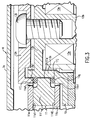
- FIG. 4 A variation of the invention illustrated and discussed in connection with Fig. 3 is seen in Fig. 4.
- the internal annular flange 11f of the memory disk support ring 11 is chamfered at its inner edge to provide converging surfaces, 11f1, 11f2, which converge in the direction of the cylindrical body 13a.
- the elastomeric toroids 11j are now compressed between the peripheral rim 13g1 of the clamp 13h and the converging surface 11f at the top of the stack, and, the shoulder 13g and the converging surface 11f2 at the bottom of the stack.
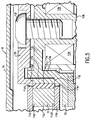
- Fig. 5 illustrates a different approach to the soft or compliant mounting of the disk pack 11.
- the memory disk support ring 11d and a mounting ring 11k of metal are concentrically positioned and bonded together by an elastomeric ring 11m disposed in a concentric position therebetween.
- the elastomeric material 11m is selected to have the required compliance and damping for this installation.
- a suitable material is butyl rubber, fluorocarbon-based compounds, etc.
- Clamping pressure is now applied by the clamp 13h, the peripheral edge 13g1 of which seats upon the upper edge of the mounting ring 11k, the bottom edge of the mounting ring 11k being seated upon the shoulder 13g on the tubular body 13a. Clamping pressure is applied in that degree required to avoid slippage of the ring 11k at the interfaces 13g and 13g1 in the environment of use of the disk drive 6.
Landscapes
- Holding Or Fastening Of Disk On Rotational Shaft (AREA)
Applications Claiming Priority (2)
| Application Number | Priority Date | Filing Date | Title |
|---|---|---|---|
| US08/250,900 US5422768A (en) | 1994-05-31 | 1994-05-31 | Compliant hard disk assembly for a recording/reproducing device |
| US250900 | 1994-05-31 |
Publications (2)
| Publication Number | Publication Date |
|---|---|
| EP0685841A2 true EP0685841A2 (de) | 1995-12-06 |
| EP0685841A3 EP0685841A3 (de) | 1996-02-28 |
Family
ID=22949623
Family Applications (1)
| Application Number | Title | Priority Date | Filing Date |
|---|---|---|---|
| EP95103512A Withdrawn EP0685841A3 (de) | 1994-05-31 | 1995-03-10 | Nachgiebige Plattenspeicheranordnung für ein Aufnahme/Wiedergabegerät. |
Country Status (3)
| Country | Link |
|---|---|
| US (1) | US5422768A (de) |
| EP (1) | EP0685841A3 (de) |
| JP (1) | JPH07326154A (de) |
Families Citing this family (23)
| Publication number | Priority date | Publication date | Assignee | Title |
|---|---|---|---|---|
| US5493462A (en) * | 1994-06-03 | 1996-02-20 | Hewlett-Packard Company | Disk drive having an inwardly radially spring loaded hard ring disk pack attachment to the disk motor rotor |
| KR0149944B1 (ko) * | 1995-04-24 | 1999-04-15 | 김광호 | 하드디스크 드라이브의 디스크 고정구조체 |
| KR970008091A (ko) * | 1995-07-13 | 1997-02-24 | 김광호 | 하드 디스크 드라이버의 디스크 체결 장치 |
| US5801901A (en) * | 1996-05-08 | 1998-09-01 | Seagate Technology, Inc. | Disc drive clamp fastener including a clamp disc indentation |
| US6130801A (en) * | 1997-11-07 | 2000-10-10 | Seagate Technology, Inc. | Composite disc spacer for a disc drive |
| US6285525B1 (en) | 1998-07-01 | 2001-09-04 | 3M Innovative Properties Company | Damped spacer articles and disk drive assemblies containing damped spacer articles |
| US6064547A (en) * | 1998-09-15 | 2000-05-16 | Quantum Corporation | Damped disk separator |
| US6255750B1 (en) | 1999-04-21 | 2001-07-03 | Seagate Technology Llc | Apparatus and method for reducing disc flutter and disc vibration effects in a disc drive |
| US6368012B1 (en) | 1999-12-22 | 2002-04-09 | Abb Flexible Automation, Inc. | Compliant end effector |
| US6606221B2 (en) | 2000-11-15 | 2003-08-12 | Seagate Technology Llc | Viscoelastic disc clamp using adhesive with radial compliance |
| JP2002343002A (ja) * | 2001-05-18 | 2002-11-29 | Matsushita Electric Ind Co Ltd | ディスク装置 |
| KR100459700B1 (ko) * | 2002-02-15 | 2004-12-04 | 삼성전자주식회사 | 하드 디스크 드라이브의 디스크 클램프 |
| US6788495B2 (en) | 2002-03-11 | 2004-09-07 | Seagate Technology Llc | Disc pack assembly |
| US20040100725A1 (en) * | 2002-11-21 | 2004-05-27 | Shiao-Hua Chen | Damped disk spacer |
| JP4024217B2 (ja) * | 2004-02-16 | 2007-12-19 | 株式会社日立グローバルストレージテクノロジーズ | 磁気ディスク装置 |
| SG125940A1 (en) * | 2004-03-12 | 2006-10-30 | Seagate Technology Llc | Disc media retainer |
| US7164554B2 (en) * | 2004-06-30 | 2007-01-16 | Hitachi Global Storage Technologies Netherlands Bv | Disk drive with hub and apparatus for prevention of lubrication migration for lubricated clamp fasteners in disk drive applications |
| JP2006185560A (ja) * | 2004-12-28 | 2006-07-13 | Toshiba Corp | ディスク駆動装置、これを備えたディスク装置、およびディスク駆動装置の製造方法 |
| US20060232880A1 (en) * | 2005-04-14 | 2006-10-19 | Seagate Technology Llc | Mounting system for a storage media disc |
| JP2010067324A (ja) * | 2008-09-11 | 2010-03-25 | Hitachi Global Storage Technologies Netherlands Bv | ディスク・ドライブ及びスペーサ |
| US8049985B2 (en) * | 2009-02-03 | 2011-11-01 | Seagate Technology Llc | Variable spindle speed control for data storage devices |
| US8488270B2 (en) * | 2011-05-27 | 2013-07-16 | Western Digital Technologies, Inc. | Disk drive having a sheet metal clamp with a stamped annular protruding disk contact feature |
| US8693139B2 (en) | 2012-08-02 | 2014-04-08 | Western Digital Technologies, Inc. | Ultra-thin HDD embedded disk clamp design |
Family Cites Families (8)
| Publication number | Priority date | Publication date | Assignee | Title |
|---|---|---|---|---|
| US4545047A (en) * | 1984-01-31 | 1985-10-01 | Storage Technology Partners Ii | Centering device for interchangeable disk |
| IT1189669B (it) * | 1986-05-19 | 1988-02-04 | Olivetti & Co Spa | Dispositivo per smorzare le oscillazione di un motore a passo |
| US4945432A (en) * | 1988-03-31 | 1990-07-31 | Hoya Electronics Corporation | Magnetic disk drive with brittle disks |
| US5006942A (en) * | 1989-04-17 | 1991-04-09 | International Business Machines Corporation | Rigid magnetic data storage disk assembly with grooved spacer |
| US4999724A (en) * | 1989-11-13 | 1991-03-12 | Hewlett-Packard Company | Disk drive having an electrically isolated disk stack |
| US5317225A (en) * | 1990-12-29 | 1994-05-31 | Nippon Densan Corporation | Spindle motor and disk clamp mechanism used therein |
| US5243481A (en) * | 1991-09-25 | 1993-09-07 | Integral Peripherals, Inc. | Clamp for information storage disk |
| US5367418A (en) * | 1992-11-13 | 1994-11-22 | Maxtor Corporation | Spin motor assembly that contains an O-ring which supports a disk in both the radial and axial directions |
-
1994
- 1994-05-31 US US08/250,900 patent/US5422768A/en not_active Expired - Fee Related
-
1995
- 1995-03-10 EP EP95103512A patent/EP0685841A3/de not_active Withdrawn
- 1995-05-31 JP JP7157079A patent/JPH07326154A/ja active Pending
Also Published As
| Publication number | Publication date |
|---|---|
| JPH07326154A (ja) | 1995-12-12 |
| EP0685841A3 (de) | 1996-02-28 |
| US5422768A (en) | 1995-06-06 |
Similar Documents
| Publication | Publication Date | Title |
|---|---|---|
| US5422768A (en) | Compliant hard disk assembly for a recording/reproducing device | |
| US6480363B1 (en) | Hard disk drive actuator assembly with damped tolerance ring for enhancing drive performance during structural resonance modes | |
| US5663851A (en) | Spindle hub assembly for a hard disk drive having a disk-clamp spacer for absorbing vibrations and evenly distributing the clamping forces | |
| KR100268496B1 (ko) | 하드디스크드라이브모터베이스어셈블리및그양평면균형맞추는방법 | |
| US5459627A (en) | Disk drive having an O-ring disk clamp | |
| US6556387B1 (en) | Controlling mechanical response characteristics of a disc drive actuator by adjusting a fastener engaging the actuator shaft to vary axial force on the bearing assembly | |
| US6255750B1 (en) | Apparatus and method for reducing disc flutter and disc vibration effects in a disc drive | |
| US6407882B1 (en) | Structure for suppressing vibration of spindle motor in disk drive | |
| JPH03505499A (ja) | ディスク・ファイルの組立方法 | |
| US6822826B2 (en) | Disc fixing apparatus and associated method fixing a disc and motor in balanced rotation | |
| JPH10134502A (ja) | スピンドルモータの回転アンバランス修正機構 | |
| EP0572949A1 (de) | Eingebauter Festplattenantrieb mit einstückiger herausnehmbarer Plattenstapelstruktur | |
| JPH07334984A (ja) | ディスク・パックの取付け装置 | |
| JPS60138746A (ja) | 対物レンズ駆動装置およびその製造方法 | |
| US6414817B1 (en) | High friction disc support member to increase disc drive mechanical shock resistance | |
| US6882494B2 (en) | Sensor system for disk device using floating head | |
| US7061723B2 (en) | Bilinear-nonlinear limit stop for hard disk drive actuator | |
| JPH06259905A (ja) | 記録再生装置用アクチュエータ及びこれを用いた記録再生装置 | |
| US6961216B2 (en) | Hard disk drive with disk clamp inner wall engaging bearing sleeve outer wall | |
| WO1990013167A1 (en) | Stabilized disk drive spin motor | |
| US20030192166A1 (en) | Disk pack balancing method using spindle hub vibration | |
| US6424488B1 (en) | Peripherally extending disc ring to limit disc deflection and to provide disc stack balancing | |
| US6809907B1 (en) | Remote-operated integrated microactuator, in particular for a read/write transducer of hard disks | |
| JPH04184758A (ja) | ディスク駆動装置 | |
| EP0246375B1 (de) | Kopf/Arm-Zusammenbau und rotierender Zugangsmechanismus für einen Plattenspeicher |
Legal Events
| Date | Code | Title | Description |
|---|---|---|---|
| PUAI | Public reference made under article 153(3) epc to a published international application that has entered the european phase |
Free format text: ORIGINAL CODE: 0009012 |
|
| AK | Designated contracting states |
Kind code of ref document: A2 Designated state(s): DE FR GB |
|
| PUAL | Search report despatched |
Free format text: ORIGINAL CODE: 0009013 |
|
| AK | Designated contracting states |
Kind code of ref document: A3 Designated state(s): DE FR GB |
|
| 17P | Request for examination filed |
Effective date: 19960207 |
|
| STAA | Information on the status of an ep patent application or granted ep patent |
Free format text: STATUS: THE APPLICATION HAS BEEN WITHDRAWN |
|
| 18W | Application withdrawn |
Withdrawal date: 19961119 |