EP0685856A2 - Isolationsanordnung für ein geschweisstes hermetisches Endstück - Google Patents
Isolationsanordnung für ein geschweisstes hermetisches Endstück Download PDFInfo
- Publication number
- EP0685856A2 EP0685856A2 EP95630033A EP95630033A EP0685856A2 EP 0685856 A2 EP0685856 A2 EP 0685856A2 EP 95630033 A EP95630033 A EP 95630033A EP 95630033 A EP95630033 A EP 95630033A EP 0685856 A2 EP0685856 A2 EP 0685856A2
- Authority
- EP
- European Patent Office
- Prior art keywords
- pin
- aperture
- periphery
- terminal
- housing wall
- Prior art date
- Legal status (The legal status is an assumption and is not a legal conclusion. Google has not performed a legal analysis and makes no representation as to the accuracy of the status listed.)
- Granted
Links
- 238000007789 sealing Methods 0.000 claims description 11
- 238000007373 indentation Methods 0.000 claims description 10
- 239000011521 glass Substances 0.000 claims description 8
- 238000010276 construction Methods 0.000 claims description 6
- 230000002093 peripheral effect Effects 0.000 claims description 5
- 229910010293 ceramic material Inorganic materials 0.000 claims description 2
- 239000000919 ceramic Substances 0.000 claims 1
- 230000001788 irregular Effects 0.000 claims 1
- 239000000463 material Substances 0.000 description 5
- 238000000576 coating method Methods 0.000 description 4
- 238000004519 manufacturing process Methods 0.000 description 3
- 230000000712 assembly Effects 0.000 description 2
- 238000000429 assembly Methods 0.000 description 2
- 238000012423 maintenance Methods 0.000 description 2
- VYZAMTAEIAYCRO-UHFFFAOYSA-N Chromium Chemical compound [Cr] VYZAMTAEIAYCRO-UHFFFAOYSA-N 0.000 description 1
- 230000015556 catabolic process Effects 0.000 description 1
- 229910052804 chromium Inorganic materials 0.000 description 1
- 239000011651 chromium Substances 0.000 description 1
- 239000011248 coating agent Substances 0.000 description 1
- 238000005260 corrosion Methods 0.000 description 1
- 230000007797 corrosion Effects 0.000 description 1
- 230000007812 deficiency Effects 0.000 description 1
- 238000006731 degradation reaction Methods 0.000 description 1
- 239000012212 insulator Substances 0.000 description 1
- 229910052751 metal Inorganic materials 0.000 description 1
- 239000002184 metal Substances 0.000 description 1
- 239000004033 plastic Substances 0.000 description 1
- 238000011112 process operation Methods 0.000 description 1
- 238000007493 shaping process Methods 0.000 description 1
- 239000004447 silicone coating Substances 0.000 description 1
- 229910001220 stainless steel Inorganic materials 0.000 description 1
- 239000010935 stainless steel Substances 0.000 description 1
Images

Classifications
-
- H—ELECTRICITY
- H01—ELECTRIC ELEMENTS
- H01R—ELECTRICALLY-CONDUCTIVE CONNECTIONS; STRUCTURAL ASSOCIATIONS OF A PLURALITY OF MUTUALLY-INSULATED ELECTRICAL CONNECTING ELEMENTS; COUPLING DEVICES; CURRENT COLLECTORS
- H01R13/00—Details of coupling devices of the kinds covered by groups H01R12/70 or H01R24/00 - H01R33/00
- H01R13/46—Bases; Cases
- H01R13/52—Dustproof, splashproof, drip-proof, waterproof, or flameproof cases
-
- H—ELECTRICITY
- H01—ELECTRIC ELEMENTS
- H01B—CABLES; CONDUCTORS; INSULATORS; SELECTION OF MATERIALS FOR THEIR CONDUCTIVE, INSULATING OR DIELECTRIC PROPERTIES
- H01B17/00—Insulators or insulating bodies characterised by their form
- H01B17/26—Lead-in insulators; Lead-through insulators
- H01B17/30—Sealing
- H01B17/303—Sealing of leads to lead-through insulators
- H01B17/305—Sealing of leads to lead-through insulators by embedding in glass or ceramic material
Definitions
- the present invention relates to hermetic terminal assembly construction and more particularly to a terminal pin insulating arrangement for a hermetic terminal structure adapted to be sealed along the periphery of an aperture in a chamber defining housing wall.
- the present invention recognizes that such outside insulative coatings as used in the prior art have been comparatively expensive and complex in materials, manufacture, application, durability and maintenance, necessarily requiring a uniformly even body surface for application and having limitations in bonding ability and resistance to degradation with temperature variations accompanied by occasional "doming" of the body surface during high pressure operations.
- the present invention recognizing these deficiencies in the prior art outside insulative coating practices provides for an economic and straightforward insulating structure which accommodates for high temperature variations and which allows for indentations of the cup shaped body member, resisting possible "doming" as a consequence of high pressures in the hermetically sealed housing chamber.
- the present invention provides for the economical, low cost use of existing materials, allowing for ready manufacture and assembly with minimal maintenance and, at the same time, insuring extended oversurfaces to reduce the possibilities of undesirable arcing. Further, the present invention allows for unitary manufacture of substantially identical mirror-image sleeve pairs when so desired, thus reducing the costs and number of process operations and, at the same time, providing terminal pin shielding.
- the present invention provides a hermetic terminal assembly structure adapted to be sealed along the periphery of an aperture in a chamber defining housing wall comprising: a terminal pin capable of extending through the aperture of the housing wall to include inner and outer pin portions extending respectively within and without the housing wall; sealing assembly means including a coalescent bonding material or seal cooperative and extending between the periphery of the terminal pin between the inner and outer pin portions and the periphery of the aperture in the housing wall to hermetically seal the inner portion of the terminal pin within the housing wall and the outer portion of the terminal pin without the housing wall; and, a pair of sleeve members respectively surrounding the inner and outer pin portions of the terminal pin, at least one of the sleeve members being shaped to form a well recess surrounding a part of the peripheral surface of a pin portion to provide an extended oversurface with the pin portion to reduce possible arcing of the pin portion, the pair of sleeve members being sealingly cooperative with the coalescent bonding seal of the sealing assembly means.
- the present invention provides a modified arrangement wherein the pair of insulating sleeve members are joined together by an intermediate neck portion to provide an integral sleeve construction through which the terminal pin passes and seals to the inner periphery thereof, the outer periphery of the intermediate neck portion sealing to the periphery of the aperture in the housing wall.
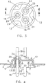
- Hermetic terminal assembly 2 which can be appropriately sized and shaped to be sealed in an aperture 3 of chamber defining housing wall 4 ( Figure 4) is disclosed.
- Chamber defining housing wall 4 can be part of a housing of a refrigerator compressor (not shown).
- Hermetic terminal assembly 2 includes a cup-shaped body which can be formed from a suitable material, such as metal or even plastic material, to include a bottom wall 7 having an inner face 8, an outer face 9 and a flared rim or side wall 11 which extends from the inner face 8 of bottom wall 7.
- bottom wall 7 advantageously can include a plurality of preselectively shaped and positioned stamped indentations 12, here shown as spaced triangles with the base of each triangle extending inwardly toward the center from the periphery of bottom wall 7, so as to spacedly surround the disclosed group of apertures 13 extending through bottom wall 7.
- These novel indentations 12 serve to strengthen bottom wall 7 and to resist possible "doming" of the bottom wall as a consequence of high pressure variations which might occur within the chamber defining wall 4. It is to be noted that this feature of indentations is, in turn, a consequence of the overall unique structural arrangement described herein and particularly the novel terminal pin insulating arrangement described hereinafter.
- the present invention should not be considered as limited to the particular indentation arrangement disclosed, including the spacing and shaping of the indentations, but that other indentation shapes and other spacings can be employed, depending upon the overall terminal assembly construction, without departing from the scope or spirit of the invention. Further, it is to be understood that the present invention should not be considered as limited to the particular aperture arrangement for the cup shaped body as disclosed, but that other aperture arrangements, including one or more apertures, can also be utilized.
- the cup shaped body 6 is, in fact, provided with three spaced apertures 13, each of which includes an annular sealing lip 14 extending from the inner face 8 of bottom wall 7.
- Apertures 13, each serve to accommodate a terminal electrical current conducting pin 16 which advantageously can be formed from a corrosion resistant stainless steel with high chromium content.
- Each pin 16, extending through bottom wall aperture 13 includes an inner pin portion 17 to extend within and be hermetically sealed within a chamber defined by the chamber defining housing wall 4 and an outer pin portion 18 extending without or outside such defined chamber. Except for reduced fuse-like section 19, each terminal pin disclosed is of uniform cross-section with fuse like section 19 being a part of the outer pin portion 18.
- the outer pin portion 18 serves to be connected to a suitable electric current source not shown and the inner pin portion 17 to an electrical unit (not shown) within the chamber defined by wall 4 (not shown). It is to be understood that, if so desired, such a fuse-like section can be positioned in inner pin portion 17 instead, or fuse-like sections can be positioned in both pin portions, or even can be entirely excluded as part of the terminal pin.
- a coalescent glass seal 21 is provided to extend between the periphery of each of the terminal pins 16 (here shown as being from the periphery of inner pin portion 17) to the periphery of a lip portion 14 serving to define aperture 13 in bottom wall 7 so as to hermetically seal the inner pin portion 17 of terminal pin 16 within aperture 13 and the outer pin portion 18 of pin 16 without or outside aperture 13.
- a pair of inner and outer insulating sleeve members 22 and 23 are provided to respectively surround inner pin portion 17 and outer pin portion 18 of each terminal pin 16.
- the insulating sleeve member pair 22 and 23 advantageously can be of a suitably selected ceramic material with the sleeves of the pair positioned in spaced mirror-image relationship so that the proximal ends thereof are in spaced and sealingly embedded relation with coalescent glass seal 21 on opposite sided thereof.
- the distal ends of each pair of inner and outer sleeves are so shaped to each form a well recess 24 which surrounds a part of the peripheral surface of the inner and outer pin portions 17 and 18 respectively.
- each inner and outer pin portion is provided with an extended oversurface to reduce possible arcing of both the inner and outer pin portions so that prior art outer cup shaped body coatings are eliminated and the possibilities of "doming" minimized. It is to be further noted that a major portion of each of the fuse-like sections 19 can be arranged to fall within a well recess 24 to thus allow a reducation of overall pin length.
- a modified embodiment of the invention is disclosed to include for each aperture 13 an integral sleeve arrangement 26 comprised of a pair of mirror-image inner and outer sleeve members 27 and 28 respectively.
- Each sleeve pair 27 and 28 is similar in shape and size to aforedescribed sleeve pair 22 and 23, with each sleeve of a pair including a wall recess 29 similar to well recess 24.
- each sleeve pair 27 and 28 in sleeve arrangement 26 are integrally joined at opposite ends by tubular neck portion 31 to thus provide an integral sleeve construction through which terminal pin 32, similar to terminal pin 16, passes.
- the inner periphery of pin 32 is sealed to the inner periphery of tubular neck portion 31 by annular glass seal 33 and the outer periphery of tubular neck portion 31 is sealed to the annular sealing lip 14 defining aperture 13 by outer split annular glass seal 34.
- the modified integral structural sleeve arrangement 26, of Figure 2 provides an inner and outer insulating sleeve member to insulatively surround, protect and create an oversurface for both the inner and outer pin portions in a manner similar to aforedescribed spaced insulator sleeves 22 and 23 of Figures 1, 3 and 4.
- the present invention is not to be considered as limited to the particular cup shaped body, as disclosed, the features of the present invention being employable in other hermetic terminal assemblies where at least one terminal pin passes through an aperture in a chamber defining housing wall and desirably is hermetically sealed thereto to provide inner and outer pin portions for electrical current connections.
Landscapes
- Chemical & Material Sciences (AREA)
- Engineering & Computer Science (AREA)
- Ceramic Engineering (AREA)
- Connections Arranged To Contact A Plurality Of Conductors (AREA)
- Manufacture Of Motors, Generators (AREA)
- Piezo-Electric Or Mechanical Vibrators, Or Delay Or Filter Circuits (AREA)
- Butt Welding And Welding Of Specific Article (AREA)
- Coupling Device And Connection With Printed Circuit (AREA)
Applications Claiming Priority (2)
| Application Number | Priority Date | Filing Date | Title |
|---|---|---|---|
| US08/251,340 US5493073A (en) | 1994-05-31 | 1994-05-31 | Insulating arrangement for a fused hermetic terminal assembly |
| US251340 | 1994-05-31 |
Publications (3)
| Publication Number | Publication Date |
|---|---|
| EP0685856A2 true EP0685856A2 (de) | 1995-12-06 |
| EP0685856A3 EP0685856A3 (de) | 1996-09-11 |
| EP0685856B1 EP0685856B1 (de) | 1999-03-10 |
Family
ID=22951530
Family Applications (1)
| Application Number | Title | Priority Date | Filing Date |
|---|---|---|---|
| EP95630033A Expired - Lifetime EP0685856B1 (de) | 1994-05-31 | 1995-04-20 | Isolationsanordnung für ein geschweisstes hermetisches Endstück |
Country Status (10)
| Country | Link |
|---|---|
| US (1) | US5493073A (de) |
| EP (1) | EP0685856B1 (de) |
| JP (1) | JP3449575B2 (de) |
| KR (1) | KR100351541B1 (de) |
| CN (1) | CN1067180C (de) |
| AT (1) | ATE177559T1 (de) |
| BR (1) | BR9501867A (de) |
| CA (1) | CA2146956C (de) |
| DE (1) | DE69508145T2 (de) |
| IL (1) | IL113300A (de) |
Cited By (1)
| Publication number | Priority date | Publication date | Assignee | Title |
|---|---|---|---|---|
| EP2297821A4 (de) * | 2008-05-19 | 2014-03-12 | Emerson Electric Co | Durchspeisung eines elektrischen stromversorgungsanschlusses |
Families Citing this family (42)
| Publication number | Priority date | Publication date | Assignee | Title |
|---|---|---|---|---|
| US6114633A (en) * | 1998-04-30 | 2000-09-05 | Tecumseh Products Company | Hermetic terminal with conductor pin identifier |
| US6325339B1 (en) * | 1998-06-22 | 2001-12-04 | William L. Lewis | Accessory device for communications headset |
| US6107566A (en) * | 1998-11-07 | 2000-08-22 | Emerson Electric Co. | Hermetic terminal structure |
| US6509525B2 (en) | 1998-11-07 | 2003-01-21 | Emerson Electric Co. | Hermetic terminal assembly |
| JP2001093596A (ja) * | 1999-09-28 | 2001-04-06 | Nec Kansai Ltd | 気密端子 |
| US6273754B1 (en) | 2000-04-13 | 2001-08-14 | Tecumseh Products Company | Protective covering for the terminal assembly of a hermetic compressor assembly |
| GB2368549B (en) * | 2000-11-02 | 2004-04-28 | Rolls Royce Plc | Apparatus for performing foundary work |
| US6555754B2 (en) | 2001-01-18 | 2003-04-29 | Walbro Corporation | Automotive fuel tank electrical fitting |
| US6632104B2 (en) * | 2002-02-08 | 2003-10-14 | Emerson Electric Co. | Hermetic terminal assembly |
| US6851962B2 (en) * | 2002-04-01 | 2005-02-08 | Hermetic Seal Corp. | Hermetic connector |
| US6844502B2 (en) * | 2002-05-16 | 2005-01-18 | Emerson Electric Co. | Hermetically sealed current conducting terminal assembly |
| KR100913265B1 (ko) * | 2002-07-30 | 2009-08-21 | 엘지전자 주식회사 | 전원 공급 단자 |
| DE10334394B3 (de) * | 2003-07-28 | 2004-11-18 | Tuilaser Ag | Durchführungsvorrichtung für Laserröhren |
| US7059879B2 (en) * | 2004-05-20 | 2006-06-13 | Hubbell Incorporated | Electrical connector having a piston-contact element |
| KR101063674B1 (ko) | 2005-05-10 | 2011-09-07 | 현대자동차주식회사 | 열해가 방지되는 배선 연결체를 구비한 산소 센서 구조 |
| EP1902496B1 (de) * | 2005-07-05 | 2012-09-05 | Emerson Electric Co. | Stromanschlussdurchführung |
| US7683264B2 (en) * | 2006-09-19 | 2010-03-23 | Ut-Battelle, Llc | High pressure, high current, low inductance, high reliability sealed terminals |
| US8262372B2 (en) | 2007-05-10 | 2012-09-11 | Emerson Climate Technologies, Inc. | Compressor hermetic terminal |
| US8939734B2 (en) * | 2007-08-28 | 2015-01-27 | Emerson Climate Technologies, Inc. | Molded plug for a compressor |
| US8939735B2 (en) * | 2009-03-27 | 2015-01-27 | Emerson Climate Technologies, Inc. | Compressor plug assembly |
| US8968018B2 (en) * | 2009-08-05 | 2015-03-03 | Teledyne Instruments, Inc. | Electrical penetrator assembly |
| CN101707310B (zh) * | 2009-09-30 | 2012-01-04 | 中航光电科技股份有限公司 | 密封转接连接器 |
| DE102010029982A1 (de) | 2010-06-11 | 2011-12-15 | Robert Bosch Gmbh | Fluiddichtender Elektromotor-Anschlussstecker, sowie Motor und konfektioniertes elektrisches Kabel |
| US9279425B2 (en) * | 2010-07-26 | 2016-03-08 | Bristol Compressors Interntional, Inc. | Hermetic electrical feedthrough assembly for a compressor |
| DE102011080277A1 (de) * | 2011-08-02 | 2013-02-07 | Robert Bosch Gmbh | Durchführungsvorrichtung durch ein Metallblech für mindestens ein Elektroverbindungselement zu einer elektronischen Schaltung |
| JP5924766B2 (ja) * | 2012-03-26 | 2016-05-25 | エヌイーシー ショット コンポーネンツ株式会社 | ヒューズ機能付き気密端子 |
| US9480177B2 (en) | 2012-07-27 | 2016-10-25 | Emerson Climate Technologies, Inc. | Compressor protection module |
| WO2015031630A1 (en) * | 2013-08-28 | 2015-03-05 | Heartware, Inc. | Pass-through assembly |
| ITUB20152903A1 (it) | 2014-08-14 | 2017-02-05 | Schott Ag | Passaggio elettrico e suo utilizzo |
| US9553398B2 (en) * | 2015-06-05 | 2017-01-24 | General Electric Company | Hermetic feed through assembly |
| JP6293095B2 (ja) * | 2015-07-06 | 2018-03-14 | ショット日本株式会社 | ヒューズ付き気密端子 |
| EP3252894A1 (de) * | 2016-05-30 | 2017-12-06 | Siemens Aktiengesellschaft | Eindringvorrichtung für hochdruckanwendung |
| USD832795S1 (en) * | 2017-01-17 | 2018-11-06 | Schott Japan Corporation | Hermetic terminal |
| USD832794S1 (en) * | 2017-01-17 | 2018-11-06 | Schott Japan Corporation | Hermetic terminal |
| JP7231339B2 (ja) * | 2018-06-01 | 2023-03-01 | ショット日本株式会社 | 気密端子 |
| EP4003765B1 (de) | 2019-07-31 | 2024-09-11 | Firestone Industrial Products Company, LLC | Gasfederverschlusskappe sowie gasfeder- und dämpferanordnung und diese enthaltende verfahren |
| KR102217163B1 (ko) * | 2019-09-02 | 2021-02-18 | 한국가스공사 | 진동센서 피드스루 |
| USD895421S1 (en) * | 2019-10-31 | 2020-09-08 | Rodney Laible | Dual straw container insert |
| USD899925S1 (en) * | 2019-10-31 | 2020-10-27 | Rodney Laible | Dual draw cap adapter |
| CN112271479B (zh) * | 2020-10-29 | 2025-05-23 | 合兴汽车电子股份有限公司 | 连接器的插针、连接器及变速箱 |
| DE102022101681B4 (de) * | 2022-01-25 | 2024-06-06 | Hanon Systems | Dichtungsanordnung für eine Vorrichtung zum Antreiben eines Verdichters |
| EP4717918A1 (de) | 2024-09-25 | 2026-04-01 | Schott Ag | Elektrische durchführungsanordnung |
Family Cites Families (12)
| Publication number | Priority date | Publication date | Assignee | Title |
|---|---|---|---|---|
| US3160460A (en) * | 1962-01-17 | 1964-12-08 | Fusite Corp | Terminal assembly having conductor pins and connector block |
| US3605076A (en) * | 1969-08-21 | 1971-09-14 | Us Terminals Inc | Hermetically sealed terminal construction |
| US3988053A (en) * | 1975-01-20 | 1976-10-26 | Dodenhoff John A | Hermetic terminal |
| US4174145A (en) * | 1976-12-29 | 1979-11-13 | The United States Of America As Represented By The United States Department Of Energy | High pressure electrical insulated feed thru connector |
| US4252394A (en) * | 1979-05-16 | 1981-02-24 | Tecumseh Products Company | Hermetic compressor motor terminal |
| US4296275A (en) * | 1980-06-09 | 1981-10-20 | Emerson Electric Co. | Hermetic refrigeration terminal |
| US4584433A (en) * | 1984-12-03 | 1986-04-22 | Emerson Electric Co. | Hermetic terminal assembly |
| US4609774A (en) * | 1985-06-18 | 1986-09-02 | B & W Electronic Enclosures, Inc. | Electrical terminal construction with fusible section |
| US4964788A (en) * | 1990-03-21 | 1990-10-23 | Tecumseh Products Company | Hermetic terminal with terminal pin assemblies having fusible links and motor compressor unit including same |
| US5017740A (en) * | 1990-04-02 | 1991-05-21 | Emerson Electric Co. | Fused hermetic terminal assembly including a pin guard and lead wire end connection securing device associated therewith |
| US5227587A (en) * | 1991-05-13 | 1993-07-13 | Emerson Electric Co. | Hermetic assembly arrangement for a current conducting pin passing through a housing wall |
| JP3020341B2 (ja) * | 1992-03-18 | 2000-03-15 | 松下冷機株式会社 | 気密端子保護カバー |
-
1994
- 1994-05-31 US US08/251,340 patent/US5493073A/en not_active Expired - Lifetime
-
1995
- 1995-04-07 IL IL113300A patent/IL113300A/en not_active IP Right Cessation
- 1995-04-12 CA CA002146956A patent/CA2146956C/en not_active Expired - Fee Related
- 1995-04-18 KR KR1019950009024A patent/KR100351541B1/ko not_active Expired - Lifetime
- 1995-04-20 AT AT95630033T patent/ATE177559T1/de not_active IP Right Cessation
- 1995-04-20 EP EP95630033A patent/EP0685856B1/de not_active Expired - Lifetime
- 1995-04-20 DE DE69508145T patent/DE69508145T2/de not_active Expired - Lifetime
- 1995-04-27 JP JP12732995A patent/JP3449575B2/ja not_active Expired - Lifetime
- 1995-04-28 BR BR9501867A patent/BR9501867A/pt not_active Application Discontinuation
- 1995-04-29 CN CN95105424A patent/CN1067180C/zh not_active Expired - Lifetime
Cited By (1)
| Publication number | Priority date | Publication date | Assignee | Title |
|---|---|---|---|---|
| EP2297821A4 (de) * | 2008-05-19 | 2014-03-12 | Emerson Electric Co | Durchspeisung eines elektrischen stromversorgungsanschlusses |
Also Published As
| Publication number | Publication date |
|---|---|
| DE69508145T2 (de) | 1999-10-28 |
| HK1006264A1 (en) | 1999-02-19 |
| CA2146956A1 (en) | 1995-12-01 |
| DE69508145D1 (de) | 1999-04-15 |
| KR950034912A (ko) | 1995-12-28 |
| KR100351541B1 (ko) | 2003-01-24 |
| CN1067180C (zh) | 2001-06-13 |
| US5493073A (en) | 1996-02-20 |
| CN1120749A (zh) | 1996-04-17 |
| AU1774895A (en) | 1995-12-07 |
| IL113300A0 (en) | 1995-07-31 |
| JPH07326409A (ja) | 1995-12-12 |
| IL113300A (en) | 1998-02-08 |
| EP0685856A3 (de) | 1996-09-11 |
| EP0685856B1 (de) | 1999-03-10 |
| ATE177559T1 (de) | 1999-03-15 |
| BR9501867A (pt) | 1996-01-02 |
| JP3449575B2 (ja) | 2003-09-22 |
| CA2146956C (en) | 1998-10-27 |
| AU681011B2 (en) | 1997-08-14 |
Similar Documents
| Publication | Publication Date | Title |
|---|---|---|
| EP0685856B1 (de) | Isolationsanordnung für ein geschweisstes hermetisches Endstück | |
| EP0184538B1 (de) | Hermetische Endanschlussklemmvorrichtung | |
| CA1217537A (en) | Hermetic terminal assembly | |
| EP1902496B1 (de) | Stromanschlussdurchführung | |
| CA2148846C (en) | Electrical connector with grommet and filter | |
| US3770878A (en) | Hermetically sealed electrical terminal | |
| US6107566A (en) | Hermetic terminal structure | |
| US6699078B2 (en) | Connector block having at least one protrusion, for a terminal assembly | |
| WO2001017071A1 (en) | Connector block for a terminal assembly | |
| US4700999A (en) | Current leadthrough | |
| HK1006264B (en) | Insulating arrangement for a fused hermetic terminal assembly | |
| KR100336078B1 (ko) | 리드스위치 | |
| KR0135981B1 (ko) | 단부 기밀조립체에 대한 슬리이브 배열 | |
| CA2084119A1 (en) | Hermetically Sealed Snap Switch Arrangement | |
| EP0095327B1 (de) | Vakuumschalter | |
| NL8503034A (nl) | Elektrische kontaktvasthoudinrichting. | |
| JP2000150021A (ja) | 保持部材と該保持部材内に鋳込まれた接点ピンとから成るユニット部品 | |
| KR19980031117A (ko) | 진공인터럽터의 센터실드 고정장치 | |
| US5045756A (en) | Non-conductive collar for the conductive shell of an electrical discharge device | |
| KR930005788Y1 (ko) | 브라운관의 스템 및 베이스 구조 | |
| KR0120628Y1 (ko) | 마그네트론 | |
| NZ510729A (en) | High voltage circuit breaker and assembling method | |
| JPH0393134A (ja) | マグネトロンの陰極構体 | |
| JPH07211386A (ja) | 密封型電気コネクタ |
Legal Events
| Date | Code | Title | Description |
|---|---|---|---|
| PUAI | Public reference made under article 153(3) epc to a published international application that has entered the european phase |
Free format text: ORIGINAL CODE: 0009012 |
|
| AK | Designated contracting states |
Kind code of ref document: A2 Designated state(s): AT CH DE FR GB IT LI NL |
|
| PUAL | Search report despatched |
Free format text: ORIGINAL CODE: 0009013 |
|
| AK | Designated contracting states |
Kind code of ref document: A3 Designated state(s): AT CH DE FR GB IT LI NL |
|
| 17P | Request for examination filed |
Effective date: 19961108 |
|
| GRAG | Despatch of communication of intention to grant |
Free format text: ORIGINAL CODE: EPIDOS AGRA |
|
| 17Q | First examination report despatched |
Effective date: 19980505 |
|
| GRAG | Despatch of communication of intention to grant |
Free format text: ORIGINAL CODE: EPIDOS AGRA |
|
| GRAH | Despatch of communication of intention to grant a patent |
Free format text: ORIGINAL CODE: EPIDOS IGRA |
|
| GRAH | Despatch of communication of intention to grant a patent |
Free format text: ORIGINAL CODE: EPIDOS IGRA |
|
| GRAA | (expected) grant |
Free format text: ORIGINAL CODE: 0009210 |
|
| AK | Designated contracting states |
Kind code of ref document: B1 Designated state(s): AT CH DE FR GB IT LI NL |
|
| REF | Corresponds to: |
Ref document number: 177559 Country of ref document: AT Date of ref document: 19990315 Kind code of ref document: T |
|
| REG | Reference to a national code |
Ref country code: CH Ref legal event code: EP |
|
| REF | Corresponds to: |
Ref document number: 69508145 Country of ref document: DE Date of ref document: 19990415 |
|
| ET | Fr: translation filed | ||
| PLBE | No opposition filed within time limit |
Free format text: ORIGINAL CODE: 0009261 |
|
| STAA | Information on the status of an ep patent application or granted ep patent |
Free format text: STATUS: NO OPPOSITION FILED WITHIN TIME LIMIT |
|
| 26N | No opposition filed | ||
| REG | Reference to a national code |
Ref country code: GB Ref legal event code: IF02 |
|
| PGFP | Annual fee paid to national office [announced via postgrant information from national office to epo] |
Ref country code: NL Payment date: 20050329 Year of fee payment: 11 |
|
| PGFP | Annual fee paid to national office [announced via postgrant information from national office to epo] |
Ref country code: AT Payment date: 20050401 Year of fee payment: 11 |
|
| PGFP | Annual fee paid to national office [announced via postgrant information from national office to epo] |
Ref country code: CH Payment date: 20050421 Year of fee payment: 11 |
|
| PG25 | Lapsed in a contracting state [announced via postgrant information from national office to epo] |
Ref country code: AT Free format text: LAPSE BECAUSE OF NON-PAYMENT OF DUE FEES Effective date: 20060420 |
|
| PG25 | Lapsed in a contracting state [announced via postgrant information from national office to epo] |
Ref country code: LI Free format text: LAPSE BECAUSE OF NON-PAYMENT OF DUE FEES Effective date: 20060430 Ref country code: CH Free format text: LAPSE BECAUSE OF NON-PAYMENT OF DUE FEES Effective date: 20060430 |
|
| PG25 | Lapsed in a contracting state [announced via postgrant information from national office to epo] |
Ref country code: NL Free format text: LAPSE BECAUSE OF NON-PAYMENT OF DUE FEES Effective date: 20061101 |
|
| REG | Reference to a national code |
Ref country code: CH Ref legal event code: PL |
|
| NLV4 | Nl: lapsed or anulled due to non-payment of the annual fee |
Effective date: 20061101 |
|
| PGFP | Annual fee paid to national office [announced via postgrant information from national office to epo] |
Ref country code: GB Payment date: 20140428 Year of fee payment: 20 |
|
| PGFP | Annual fee paid to national office [announced via postgrant information from national office to epo] |
Ref country code: FR Payment date: 20140417 Year of fee payment: 20 Ref country code: DE Payment date: 20140429 Year of fee payment: 20 Ref country code: IT Payment date: 20140429 Year of fee payment: 20 |
|
| REG | Reference to a national code |
Ref country code: DE Ref legal event code: R071 Ref document number: 69508145 Country of ref document: DE |
|
| REG | Reference to a national code |
Ref country code: GB Ref legal event code: PE20 Expiry date: 20150419 |
|
| PG25 | Lapsed in a contracting state [announced via postgrant information from national office to epo] |
Ref country code: GB Free format text: LAPSE BECAUSE OF EXPIRATION OF PROTECTION Effective date: 20150419 |