EP0686057B1 - Filtre a liquides - Google Patents
Filtre a liquides Download PDFInfo
- Publication number
- EP0686057B1 EP0686057B1 EP95903243A EP95903243A EP0686057B1 EP 0686057 B1 EP0686057 B1 EP 0686057B1 EP 95903243 A EP95903243 A EP 95903243A EP 95903243 A EP95903243 A EP 95903243A EP 0686057 B1 EP0686057 B1 EP 0686057B1
- Authority
- EP
- European Patent Office
- Prior art keywords
- filter
- receptacle
- channel
- liquid
- liquids according
- Prior art date
- Legal status (The legal status is an assumption and is not a legal conclusion. Google has not performed a legal analysis and makes no representation as to the accuracy of the status listed.)
- Expired - Lifetime
Links
Images

Classifications
-
- C—CHEMISTRY; METALLURGY
- C02—TREATMENT OF WATER, WASTE WATER, SEWAGE, OR SLUDGE
- C02F—TREATMENT OF WATER, WASTE WATER, SEWAGE, OR SLUDGE
- C02F1/00—Treatment of water, waste water, or sewage
- C02F1/001—Processes for the treatment of water whereby the filtration technique is of importance
- C02F1/003—Processes for the treatment of water whereby the filtration technique is of importance using household-type filters for producing potable water, e.g. pitchers, bottles, faucet mounted devices
-
- B—PERFORMING OPERATIONS; TRANSPORTING
- B01—PHYSICAL OR CHEMICAL PROCESSES OR APPARATUS IN GENERAL
- B01D—SEPARATION
- B01D24/00—Filters comprising loose filtering material, i.e. filtering material without any binder between the individual particles or fibres thereof
- B01D24/002—Filters comprising loose filtering material, i.e. filtering material without any binder between the individual particles or fibres thereof with multiple filtering elements in parallel connection
- B01D24/004—Filters comprising loose filtering material, i.e. filtering material without any binder between the individual particles or fibres thereof with multiple filtering elements in parallel connection arranged concentrically or coaxially
-
- B—PERFORMING OPERATIONS; TRANSPORTING
- B01—PHYSICAL OR CHEMICAL PROCESSES OR APPARATUS IN GENERAL
- B01D—SEPARATION
- B01D24/00—Filters comprising loose filtering material, i.e. filtering material without any binder between the individual particles or fibres thereof
- B01D24/007—Filters comprising loose filtering material, i.e. filtering material without any binder between the individual particles or fibres thereof with multiple filtering elements in series connection
- B01D24/008—Filters comprising loose filtering material, i.e. filtering material without any binder between the individual particles or fibres thereof with multiple filtering elements in series connection arranged concentrically or coaxially
-
- B—PERFORMING OPERATIONS; TRANSPORTING
- B01—PHYSICAL OR CHEMICAL PROCESSES OR APPARATUS IN GENERAL
- B01D—SEPARATION
- B01D24/00—Filters comprising loose filtering material, i.e. filtering material without any binder between the individual particles or fibres thereof
- B01D24/02—Filters comprising loose filtering material, i.e. filtering material without any binder between the individual particles or fibres thereof with the filter bed stationary during the filtration
- B01D24/10—Filters comprising loose filtering material, i.e. filtering material without any binder between the individual particles or fibres thereof with the filter bed stationary during the filtration the filtering material being held in a closed container
- B01D24/12—Downward filtration, the filtering material being supported by pervious surfaces
-
- B—PERFORMING OPERATIONS; TRANSPORTING
- B01—PHYSICAL OR CHEMICAL PROCESSES OR APPARATUS IN GENERAL
- B01D—SEPARATION
- B01D24/00—Filters comprising loose filtering material, i.e. filtering material without any binder between the individual particles or fibres thereof
- B01D24/02—Filters comprising loose filtering material, i.e. filtering material without any binder between the individual particles or fibres thereof with the filter bed stationary during the filtration
- B01D24/10—Filters comprising loose filtering material, i.e. filtering material without any binder between the individual particles or fibres thereof with the filter bed stationary during the filtration the filtering material being held in a closed container
- B01D24/18—Combined upward and downward filtration
-
- B—PERFORMING OPERATIONS; TRANSPORTING
- B01—PHYSICAL OR CHEMICAL PROCESSES OR APPARATUS IN GENERAL
- B01D—SEPARATION
- B01D24/00—Filters comprising loose filtering material, i.e. filtering material without any binder between the individual particles or fibres thereof
- B01D24/38—Feed or discharge devices
- B01D24/40—Feed or discharge devices for feeding
-
- C—CHEMISTRY; METALLURGY
- C02—TREATMENT OF WATER, WASTE WATER, SEWAGE, OR SLUDGE
- C02F—TREATMENT OF WATER, WASTE WATER, SEWAGE, OR SLUDGE
- C02F2103/00—Nature of the water, waste water, sewage or sludge to be treated
- C02F2103/42—Nature of the water, waste water, sewage or sludge to be treated from bathing facilities, e.g. swimming pools
-
- C—CHEMISTRY; METALLURGY
- C02—TREATMENT OF WATER, WASTE WATER, SEWAGE, OR SLUDGE
- C02F—TREATMENT OF WATER, WASTE WATER, SEWAGE, OR SLUDGE
- C02F2201/00—Apparatus for treatment of water, waste water or sewage
- C02F2201/002—Construction details of the apparatus
- C02F2201/006—Cartridges
Definitions
- the invention relates to a liquid filter according to the Preamble of claim 1.
- Coarse impurities get into the pool water, Turbidities, colloidal substances and microorganisms.
- filtration for example with sand, anthracite, dolomite, lava gravel, Silicates or activated carbon can cause coarse impurities and Turbidities are retained.
- some flocculants are used, which can also be separated in filters.
- certain layer heights of the filter material are prescribed or to be provided appropriately, e.g. with sand as filter material a layer height of more than 1.2 m with closed filter housings.
- the liquid filters known from the prior art exist from two half-shells held by a clamping ring become. Via a liquid inlet and a liquid outlet water is pumped through a pipe system of the container, for filtration with gravel or sand or similar filter media is filled.
- the entire inner pipe structure and the mounting elements for sieves or the like are very expensive.
- CH-A-339 911 describes a liquid filter from closed design with granular filter material, its filter bed is at least approximately cylindrical in shape.
- cylindrical filter container is a cavity between the filter container inner wall and a perforated, from a fine-mesh Tissue existing use provided for the feeding of the raw water and with a radial filter wash for the Drainage of the sludge water serves.
- a coaxial standpipe is provided for sludge water. The above a ring line and the cavity supplied water penetrates horizontally through the openings of the insert cylindrical filter bed along its entire length and flows through this in the radial direction; the drainage of the water takes place coaxially.
- DE-A-17 67 705 describes a liquid filter a closed container holding a centrally located tube has, the peripheral wall is partially or completely perforated is. Near the bottom of the container is all over or part of its circumference and the length of the container a perforated sieve plate attached to the inside of the container intended. Is between the central tube and the sieve plate granular filter material arranged. That over the central tube discharged raw water emerges from the central in a radial direction Tube and flows through the filter material radially before the cleaned liquid through an outlet is dissipated.
- DE-A-17 67 705 described a filter container, which next to the central perforated Tube instead of the sieve plate a large number of tight next to each other pipes with perforated wall has coaxially arranged and each with a fabric are enveloped so that they work as filter elements.
- the structure of the input to simplify said liquid filter without losses in quality have to be accepted.
- the simplification of the structure is said to be less expensive to manufacture enable.
- This liquid filter has on the inside wall of the container a first channel connected to the liquid inlet an outlet opening in the upper container area and a second Channel with an inlet opening in the lower container area as a connection to the liquid outlet, the channels two on the inside wall of the container standing walls and one closing the channels Cover exist.
- the Connection of the channels mentioned with the inner wall of the container are designed to save material as well as additional ones Make brackets or pipes unnecessary Water supply channel if the cover is not opened carefully excluded, since the channel for the water supply with the cover is removed with.
- the production can be done in particular one-piece construction significantly cheaper.
- the channels consist of two in parallel walls facing each other and perpendicular to the inner wall of the container and a cover substantially parallel to the inner wall of the container.
- the cover can be parallel to each other and Channel walls standing perpendicular to the inner wall of the container can be detached with be connected to the parallel walls of the channels.
- the cover about in the form of a bar, can on the parallel side walls clamped, screwed or with the state of the art Technology usual connecting means be attached.
- the container from a detachably connected to each other via a clamping ring
- Upper and lower parts exist, of which at least one is a plastic injection molded part, which is preferably in one piece with the canal walls.
- the cover about in the form of a bar, can be clamped onto the parallel side walls, screwed or with the state of the art usual lanyards.
- the liquid inlet and the liquid outlet are preferred arranged in the lower part of the container, the end face the leading upward connected to the liquid inlet first channel of the lower part on the end face of the Channel of the upper part rests. If necessary, concerned Interlock channel sections if an improvement in Sealing to the outside or to the interior of the container is required becomes.
- the first is Channel in the upper part at its liquid outlet end with a Cover provided, the holes, slots or other Has breakthroughs.
- the cover is an annular one Liquid distributor that distributes the liquid to the sand and / or Gravel fill can drain. In the lower area a finely slotted cover on the inlet opening that prevent that filter material is discharged through the drain becomes.
- the cover of the first and / or the second channel can attached by means of a clamp, snap or screw closure be so that they can be serviced or replaced are accessible.
- the Container interior for several interconnected chambers Liquid feedthrough provided, of which at least two Contain a bed of filter material or other filters, where the total height from the individual filter material beds overall one corresponding to the desired layer height Yield results.
- known design principles will be the layer height achieved by a liquid guide between the water inlet and the water outlet also has deflections. This Liquid deflections can be 180 ° deflections, so that in the liquid in opposite chambers Directions, but they can also be in one helical or spiral liquid flow consist.
- the construction height can be halved.
- at least two adjacent chambers provided with oppositely directed flows are flowable.
- the overall height is reduced to 1 / n.
- each Chamber floor or nearby bushings to the neighboring one Chamber used to the most space-saving design receive.
- the chambers are substantially vertical arranged side by side, whereby after another Embodiment of the invention concentrically at least one of the chambers arranged to another chamber and as an annular chamber is trained.
- a centric, cylindrical chamber with several, they in different Radial distances surrounding further annular chambers be provided.
- These chambers are by respective side wall and / or Bottom openings, 180 ° pipe elbows and / or overflows interconnected, in particular such that two neighboring chambers have a common cylindrical wall have. This design is not only space-consuming but also saves material.
- the one with the water outlet directly connected chamber a centrally arranged Riser pipe.
- the one introduced through the water inlet Liquid in the upper area of one of the outer ones Annular chambers introduced where it sinks down, on the principle of the communicating tubes in the riser increases accordingly and over a deeper than the water inlet Water outlet is discharged.
- a fabric filter is arranged at the water outlet.
- this fabric filter from a closed ring composite filter fabric that is between a closed Lid and bottom with an opening (to the riser pipe) is clamped.
- the filter belt wave or zigzag clamped between the lid and the bottom, so that there is an increased passage area for the water.
- a fabric filter is, for example, in EP 0 071 200 B1 described.
- the container formed in two parts, the container parts releasably together are connected. This is when the Filter material or for other work inside the container easily accessible.
- One of the container parts is preferably one removable lid.
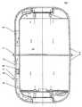
- the liquid filter shown in Fig. 1 consists of each injection molded parts, namely an upper part 10 and a lower part 11, which is held together by a clamping ring 12 become.
- the lower part 11 has an inlet 13 and one Outlet 14 to the respective through a wall opening Channels 101 and 102 lead, in the simplest case of two parallel to each other, perpendicular to the inner wall of the container Side walls and one parallel to the inner wall of the container lying cover, which is clamped or screwed on is.
- the one connected to the liquid inlet 13 Channel 101 has a lower end 103, so that pumped Water flows up the channel.
- Channel 101 ends in the upper container area and is covered with a cover Distributor 16 connected (see Fig. 2).
- This cover can have slots, Openings or similar water permeable geometries exhibit.
- a gravel and / or sand fill which as Filter material is used.
- the canal is also in the lower area 102 through one with slots, holes or other openings provided cover against the passage of filter material in shielded the channel 102.
- Channel 102 which is like channel 101 is built up, is separated by a separation 103 limited.
- the flow of liquid is schematic using arrows shown.
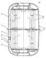
- FIG. 2 Another embodiment is shown in Fig. 2, the also consists of a cover 10 and a base part 11, which have a circular cross section and are releasably placed on top of one another are, in each case at the touchdown outer Ring beads are fixed with a clamping ring 12.
- the difference of the liquid filter shown in Fig. 2 to the above is that in the center Riser pipe 20 is provided around which one in the annular space Sand or other filter fill is arranged. About the Cover 16 provided with throughflow openings reaches the filtering liquid in a further annular space 104, the for example with activated carbon or other filter cartridges can be filled.
- a Fabric filter consisting of a perforated one Bottom 23 and a lid 24 and between the bottom and Cover clamped filter fabric 25 arranged. The water can in this way through this filter fabric Flow inside the cylinder and in a centrally arranged one Drain pipe 26 downwards, from there into the ring channel 102 to get to the liquid outlet port 14.
- the advantage this arrangement is that by the redirection or leadership of the water in a riser pipe the height of the filter container is minimized by half.
- the liquid filter shown in Fig. 3 corresponds in the outer Structure of the example shown in Fig. 1 and previously described liquid filter. However, are in the container interior 104, if necessary, in addition to one Gravel bed of activated carbon cartridges 30 with an inside Down pipe 31, through which there flowing liquid into the Drain channel 102 arrives.
Landscapes
- Chemical & Material Sciences (AREA)
- Chemical Kinetics & Catalysis (AREA)
- Life Sciences & Earth Sciences (AREA)
- Hydrology & Water Resources (AREA)
- Engineering & Computer Science (AREA)
- Environmental & Geological Engineering (AREA)
- Water Supply & Treatment (AREA)
- Organic Chemistry (AREA)
- Filtration Of Liquid (AREA)
- Water Treatment By Sorption (AREA)
- Separation Using Semi-Permeable Membranes (AREA)
- Bathtub Accessories (AREA)
Claims (10)
- Filtre de liquide, en particulier filtre d'eau pour des piscines, se composant d'un réservoir fermé avec une entrée de liquide (13) et une sortie de liquide (14), entre lesquelles est disposé du moins un corps filtrant ou du moins un lit de matière filtrante, à la paroi intérieure du réservoir étant disposés un canal (101) connecté à l'entrée de liquide et ayant une ouverture d'évacuation dans la zone supérieure du réservoir ainsi qu'un deuxième canal (102) ayant une ouverture d'admission située dans la zone inférieure du réservoir, qui sert de connexion vers la sotte de liquide,
caractérisé par le fait
que les canaux (101, 102) se composent de deux parois situées à la paroi intérieure du réservoir et d'une couverture fermant les canaux. - Filtre de liquide selon la revendication 1, caractérisé par le fait que les canaux (101, 102) se composent de deux parois disposées parallèlement entre elles et verticalement à la paroi intérieure du réservoir et d'une couverture située pour l'essentiel parallèlement a la paroi intérieure du réservoir, ladite couverture étant reliée de manière amovible aux parois parallèles des canaux (101, 102).
- Filtre de liquide selon l'une des revendications 1 ou 2, caractérisé par le fait que le réservoir se compose d'une partie supérieure (10) et d'une partie inférieure (11) qui sont reliées entre elles de manière amovible par le biais d'un anneau de serrage (12), dont l'une du moins est une pièce en matière plastique moulée par injection qui, de préférence, était fabriquée en une seule pièce avec les parois des canaux.
- Filtre de liquide selon l'une des revendications 1, 2 ou 3, caractérisé par le fait que le premier canal (101) dans la partie supérieure (10) présente à son extrémité d'évacuation de liquide une couverture (16) munie de trous, de fentes et/ou d'autres ouvertures, ou qu'une couverture finement fendue (16') munie ou dépourvue de trous est située dans la zone inférieure sur l'ouverture d'admission du deuxième canal (102).
- Filtre de liquide selon l'une des revendications 1 à 3, caractérisé par le fait que plusieurs chambres reliées entre elles et destinées au passage du liquide sont prévues à l'intérieur du réservoir, dont deux chambres au moins contiennent un lit de matière filtrante ou d'autres filtres, la hauteur totale des lits individuels de matière filtrante ou des autres filtres correspondant au total à la hauteur désirée d'empilage.
- Filtre de liquide selon la revendication 5, caractérisé par le fait que les chambres sont disposées pour l'essentiel verticalement l'une à côté de l'autre.
- Filtre de liquide selon la revendication 5 ou 6, caractérisé par le fait que l'une du moins des chambres est disposée de façon concentrique à une autre chambre et est réalisée en tant que chambre annulaire (106).
- Filtre de liquide selon l'une des revendications 6 ou 7, caractérisé par le fait que la chambre qui est reliée à la sortie de liquide (14) est un tuyau de montée (20) disposé de manière centrale et rempli d'un lit de matière filtrante ou de charbon actif.
- Filtre de liquide selon l'une des revendications 6 à 8, caractérisé par le fait qu'un canal (101) connecté à une tubulure d'admission d'eau (13) conduit vers un distributeur (16) qui est disposé dans la zone supérieure du réservoir et par l'intermédiaire duquel le liquide est distribué dans une chambre annulaire extérieure (106), qu'un tuyau de montée (20) est disposé de façon centrale dans le réservoir, à l'extrémité supérieure duquel est disposé un filtre et au-dessous de l'ouverture de fond du filtre est disposé un tuyau de descente en tant que connexion vers le canal (102) et la tubulure d'évacuation (14).
- Filtre de liquide selon l'une des revendications 1 à 9, caractérisé par le fait que l'intérieur du réservoir contient du moins une cartouche filtrante échangeable, dans laquelle ou bien dans lesquelles l'eau coule de manière radiale et peut être amené par un tuyau intérieur perforé à la sortie de liquide.
Priority Applications (1)
| Application Number | Priority Date | Filing Date | Title |
|---|---|---|---|
| EP97106607A EP0788822B1 (fr) | 1993-12-28 | 1994-12-19 | Filtre pour liquides |
Applications Claiming Priority (5)
| Application Number | Priority Date | Filing Date | Title |
|---|---|---|---|
| DE9320038U | 1993-12-28 | ||
| DE9320038 | 1993-12-28 | ||
| DE9401249U DE9401249U1 (de) | 1993-12-28 | 1994-01-26 | Flüssigkeitsfilter |
| DE9401249U | 1994-01-26 | ||
| PCT/DE1994/001507 WO1995017940A1 (fr) | 1993-12-28 | 1994-12-19 | Filtre a liquides |
Related Child Applications (1)
| Application Number | Title | Priority Date | Filing Date |
|---|---|---|---|
| EP97106607A Division EP0788822B1 (fr) | 1993-12-28 | 1994-12-19 | Filtre pour liquides |
Publications (2)
| Publication Number | Publication Date |
|---|---|
| EP0686057A1 EP0686057A1 (fr) | 1995-12-13 |
| EP0686057B1 true EP0686057B1 (fr) | 2000-03-15 |
Family
ID=25961583
Family Applications (1)
| Application Number | Title | Priority Date | Filing Date |
|---|---|---|---|
| EP95903243A Expired - Lifetime EP0686057B1 (fr) | 1993-12-28 | 1994-12-19 | Filtre a liquides |
Country Status (7)
| Country | Link |
|---|---|
| EP (1) | EP0686057B1 (fr) |
| AT (2) | ATE190518T1 (fr) |
| CZ (2) | CZ291235B6 (fr) |
| ES (1) | ES2145255T3 (fr) |
| HU (1) | HU221708B1 (fr) |
| PL (1) | PL310409A1 (fr) |
| WO (1) | WO1995017940A1 (fr) |
Family Cites Families (3)
| Publication number | Priority date | Publication date | Assignee | Title |
|---|---|---|---|---|
| NL89538C (fr) * | 1954-10-01 | |||
| FR1522285A (fr) * | 1967-02-16 | 1968-04-26 | Cie Des Eaux Et De L Ozone | Clarificateur à sable |
| NL129182C (fr) * | 1967-06-26 | 1970-02-16 |
-
1994
- 1994-12-19 HU HU9502489A patent/HU221708B1/hu not_active IP Right Cessation
- 1994-12-19 AT AT95903243T patent/ATE190518T1/de active
- 1994-12-19 PL PL94310409A patent/PL310409A1/xx unknown
- 1994-12-19 EP EP95903243A patent/EP0686057B1/fr not_active Expired - Lifetime
- 1994-12-19 AT AT97106607T patent/ATE248632T1/de not_active IP Right Cessation
- 1994-12-19 ES ES95903243T patent/ES2145255T3/es not_active Expired - Lifetime
- 1994-12-19 WO PCT/DE1994/001507 patent/WO1995017940A1/fr not_active Ceased
- 1994-12-19 CZ CZ19952197A patent/CZ291235B6/cs not_active IP Right Cessation
-
2000
- 2000-04-28 CZ CZ20001599A patent/CZ292085B6/cs not_active IP Right Cessation
Also Published As
| Publication number | Publication date |
|---|---|
| HU9502489D0 (en) | 1995-11-28 |
| WO1995017940A1 (fr) | 1995-07-06 |
| EP0686057A1 (fr) | 1995-12-13 |
| ES2145255T3 (es) | 2000-07-01 |
| ATE248632T1 (de) | 2003-09-15 |
| PL310409A1 (en) | 1995-12-11 |
| ATE190518T1 (de) | 2000-04-15 |
| CZ291235B6 (cs) | 2003-01-15 |
| CZ219795A3 (en) | 1996-02-14 |
| HUT72526A (en) | 1996-05-28 |
| CZ292085B6 (cs) | 2003-07-16 |
| HU221708B1 (hu) | 2002-12-28 |
Similar Documents
| Publication | Publication Date | Title |
|---|---|---|
| EP1317318B1 (fr) | Filtre a membrane pour traitement de l'eau | |
| DE60104156T2 (de) | Vorrichtung und Verfahren zur Reinigung von Wasser | |
| DE2349702C2 (de) | Verfahren und Vorrichtung zum Fraktionieren einer Suspension mittels Hydrozyklonen | |
| DE2547228A1 (de) | Vorrichtung mit einem buendel wirbelzyklonen | |
| WO2000010681A1 (fr) | Procede pour nettoyer des bougies d'un filtre a bougies | |
| DE3783398T2 (de) | Filteranlage. | |
| EP0686057B1 (fr) | Filtre a liquides | |
| EP1243300B1 (fr) | Filtre à bougies filtrantes pour la filtration de la bière | |
| DE10195254B4 (de) | Doppelpatronen-Mediengehäuse | |
| DE9401249U1 (de) | Flüssigkeitsfilter | |
| DE4101701C2 (de) | Filter für Kühlflüssigkeit | |
| DE3542449C1 (en) | Apparatus and method for filtering liquids | |
| EP0088237A2 (fr) | Récipient vibrant pour la floculation des eaux résiduelles obtenues par le traitement "au tonneau" | |
| WO1995017939A2 (fr) | Filtre a liquides | |
| DE3321038C2 (fr) | ||
| DE9320039U1 (de) | Flüssigkeitsfilter | |
| DE3212398A1 (de) | Aufbereitungsvorrichtung | |
| DE29908293U1 (de) | Flüssigkeitsfilter | |
| DE2528872A1 (de) | Vorrichtung zur behandlung von fluessigkeiten | |
| EP0972552B1 (fr) | Dispositif de purification de fluides | |
| DE9417638U1 (de) | Kerzenfiltervorrichtung für die Bierfiltration | |
| DE19728738C2 (de) | Filtervorrichtung zum Filtrieren von Wasser, insbesondere von Schwimmbadwasser | |
| DE2808657C3 (de) | Vorrichtung zum Trennen zweier miteinander nicht mischbarer Flüssigkeiten unterschiedlicher Dichte, vorzugsweise von Wasser-Öl-Gemischen | |
| DE2255184A1 (de) | Filter | |
| DE9409696U1 (de) | Flüssigkeitsfilter |
Legal Events
| Date | Code | Title | Description |
|---|---|---|---|
| PUAI | Public reference made under article 153(3) epc to a published international application that has entered the european phase |
Free format text: ORIGINAL CODE: 0009012 |
|
| 17P | Request for examination filed |
Effective date: 19950729 |
|
| AK | Designated contracting states |
Kind code of ref document: A1 Designated state(s): AT BE CH DE ES FR GB IT LI LU NL SE |
|
| 17Q | First examination report despatched |
Effective date: 19970121 |
|
| GRAG | Despatch of communication of intention to grant |
Free format text: ORIGINAL CODE: EPIDOS AGRA |
|
| GRAH | Despatch of communication of intention to grant a patent |
Free format text: ORIGINAL CODE: EPIDOS IGRA |
|
| RIC1 | Information provided on ipc code assigned before grant |
Free format text: 6B 01D 24/00 A, 6B 01D 24/38 B |
|
| GRAH | Despatch of communication of intention to grant a patent |
Free format text: ORIGINAL CODE: EPIDOS IGRA |
|
| GRAA | (expected) grant |
Free format text: ORIGINAL CODE: 0009210 |
|
| AK | Designated contracting states |
Kind code of ref document: B1 Designated state(s): AT BE CH DE ES FR GB IT LI LU NL SE |
|
| REF | Corresponds to: |
Ref document number: 190518 Country of ref document: AT Date of ref document: 20000415 Kind code of ref document: T |
|
| REG | Reference to a national code |
Ref country code: CH Ref legal event code: EP |
|
| XX | Miscellaneous (additional remarks) |
Free format text: TEILANMELDUNG 97106607.1 EINGEREICHT AM 22/04/97. |
|
| GBT | Gb: translation of ep patent filed (gb section 77(6)(a)/1977) |
Effective date: 20000315 |
|
| REG | Reference to a national code |
Ref country code: CH Ref legal event code: NV Representative=s name: TROESCH SCHEIDEGGER WERNER AG |
|
| REF | Corresponds to: |
Ref document number: 59409212 Country of ref document: DE Date of ref document: 20000420 |
|
| ET | Fr: translation filed | ||
| ITF | It: translation for a ep patent filed | ||
| REG | Reference to a national code |
Ref country code: ES Ref legal event code: FG2A Ref document number: 2145255 Country of ref document: ES Kind code of ref document: T3 |
|
| PG25 | Lapsed in a contracting state [announced via postgrant information from national office to epo] |
Ref country code: LU Free format text: LAPSE BECAUSE OF NON-PAYMENT OF DUE FEES Effective date: 20001219 |
|
| PLBE | No opposition filed within time limit |
Free format text: ORIGINAL CODE: 0009261 |
|
| STAA | Information on the status of an ep patent application or granted ep patent |
Free format text: STATUS: NO OPPOSITION FILED WITHIN TIME LIMIT |
|
| 26N | No opposition filed | ||
| REG | Reference to a national code |
Ref country code: GB Ref legal event code: IF02 |
|
| PGFP | Annual fee paid to national office [announced via postgrant information from national office to epo] |
Ref country code: SE Payment date: 20051214 Year of fee payment: 12 |
|
| PGFP | Annual fee paid to national office [announced via postgrant information from national office to epo] |
Ref country code: CH Payment date: 20051215 Year of fee payment: 12 |
|
| PGFP | Annual fee paid to national office [announced via postgrant information from national office to epo] |
Ref country code: FR Payment date: 20051219 Year of fee payment: 12 |
|
| PGFP | Annual fee paid to national office [announced via postgrant information from national office to epo] |
Ref country code: GB Payment date: 20051222 Year of fee payment: 12 |
|
| PGFP | Annual fee paid to national office [announced via postgrant information from national office to epo] |
Ref country code: BE Payment date: 20060116 Year of fee payment: 12 |
|
| PG25 | Lapsed in a contracting state [announced via postgrant information from national office to epo] |
Ref country code: SE Free format text: LAPSE BECAUSE OF NON-PAYMENT OF DUE FEES Effective date: 20061220 |
|
| PG25 | Lapsed in a contracting state [announced via postgrant information from national office to epo] |
Ref country code: LI Free format text: LAPSE BECAUSE OF NON-PAYMENT OF DUE FEES Effective date: 20061231 Ref country code: CH Free format text: LAPSE BECAUSE OF NON-PAYMENT OF DUE FEES Effective date: 20061231 Ref country code: BE Free format text: LAPSE BECAUSE OF NON-PAYMENT OF DUE FEES Effective date: 20061231 |
|
| REG | Reference to a national code |
Ref country code: CH Ref legal event code: PL |
|
| EUG | Se: european patent has lapsed | ||
| GBPC | Gb: european patent ceased through non-payment of renewal fee |
Effective date: 20061219 |
|
| REG | Reference to a national code |
Ref country code: FR Ref legal event code: ST Effective date: 20070831 |
|
| PG25 | Lapsed in a contracting state [announced via postgrant information from national office to epo] |
Ref country code: GB Free format text: LAPSE BECAUSE OF NON-PAYMENT OF DUE FEES Effective date: 20061219 |
|
| BERE | Be: lapsed |
Owner name: *MTS-PRODUKTE G.M.B.H. Effective date: 20061231 |
|
| PGFP | Annual fee paid to national office [announced via postgrant information from national office to epo] |
Ref country code: NL Payment date: 20071213 Year of fee payment: 14 |
|
| PGFP | Annual fee paid to national office [announced via postgrant information from national office to epo] |
Ref country code: IT Payment date: 20071222 Year of fee payment: 14 |
|
| PG25 | Lapsed in a contracting state [announced via postgrant information from national office to epo] |
Ref country code: FR Free format text: LAPSE BECAUSE OF NON-PAYMENT OF DUE FEES Effective date: 20070102 |
|
| PGFP | Annual fee paid to national office [announced via postgrant information from national office to epo] |
Ref country code: ES Payment date: 20071228 Year of fee payment: 14 |
|
| NLV4 | Nl: lapsed or anulled due to non-payment of the annual fee |
Effective date: 20090701 |
|
| PG25 | Lapsed in a contracting state [announced via postgrant information from national office to epo] |
Ref country code: NL Free format text: LAPSE BECAUSE OF NON-PAYMENT OF DUE FEES Effective date: 20090701 |
|
| REG | Reference to a national code |
Ref country code: ES Ref legal event code: FD2A Effective date: 20081220 |
|
| PG25 | Lapsed in a contracting state [announced via postgrant information from national office to epo] |
Ref country code: ES Free format text: LAPSE BECAUSE OF NON-PAYMENT OF DUE FEES Effective date: 20081220 |
|
| PGFP | Annual fee paid to national office [announced via postgrant information from national office to epo] |
Ref country code: DE Payment date: 20121108 Year of fee payment: 19 |
|
| PGFP | Annual fee paid to national office [announced via postgrant information from national office to epo] |
Ref country code: AT Payment date: 20121212 Year of fee payment: 19 |
|
| PG25 | Lapsed in a contracting state [announced via postgrant information from national office to epo] |
Ref country code: IT Free format text: LAPSE BECAUSE OF NON-PAYMENT OF DUE FEES Effective date: 20081219 |
|
| REG | Reference to a national code |
Ref country code: DE Ref legal event code: R119 Ref document number: 59409212 Country of ref document: DE |
|
| REG | Reference to a national code |
Ref country code: AT Ref legal event code: MM01 Ref document number: 190518 Country of ref document: AT Kind code of ref document: T Effective date: 20131219 |
|
| REG | Reference to a national code |
Ref country code: DE Ref legal event code: R119 Ref document number: 59409212 Country of ref document: DE Effective date: 20140701 |
|
| PG25 | Lapsed in a contracting state [announced via postgrant information from national office to epo] |
Ref country code: DE Free format text: LAPSE BECAUSE OF NON-PAYMENT OF DUE FEES Effective date: 20140701 |
|
| PG25 | Lapsed in a contracting state [announced via postgrant information from national office to epo] |
Ref country code: AT Free format text: LAPSE BECAUSE OF NON-PAYMENT OF DUE FEES Effective date: 20131219 |