EP0686364A1 - Matelas - Google Patents
Matelas Download PDFInfo
- Publication number
- EP0686364A1 EP0686364A1 EP95303871A EP95303871A EP0686364A1 EP 0686364 A1 EP0686364 A1 EP 0686364A1 EP 95303871 A EP95303871 A EP 95303871A EP 95303871 A EP95303871 A EP 95303871A EP 0686364 A1 EP0686364 A1 EP 0686364A1
- Authority
- EP
- European Patent Office
- Prior art keywords
- peripheral
- cover
- mattress
- adjacent
- fabric flange
- Prior art date
- Legal status (The legal status is an assumption and is not a legal conclusion. Google has not performed a legal analysis and makes no representation as to the accuracy of the status listed.)
- Withdrawn
Links
- 230000002093 peripheral effect Effects 0.000 claims abstract description 172
- 239000004744 fabric Substances 0.000 claims abstract description 107
- 230000003014 reinforcing effect Effects 0.000 claims description 17
- 239000000463 material Substances 0.000 claims description 9
- 238000004519 manufacturing process Methods 0.000 claims 3
- 230000000717 retained effect Effects 0.000 claims 1
- 239000012212 insulator Substances 0.000 description 7
- 229920005830 Polyurethane Foam Polymers 0.000 description 6
- 239000011496 polyurethane foam Substances 0.000 description 6
- 239000002184 metal Substances 0.000 description 3
- 238000000034 method Methods 0.000 description 2
- 241000251468 Actinopterygii Species 0.000 description 1
- 239000004743 Polypropylene Substances 0.000 description 1
- 229910000831 Steel Inorganic materials 0.000 description 1
- 241000282887 Suidae Species 0.000 description 1
- 238000010276 construction Methods 0.000 description 1
- -1 polypropylene Polymers 0.000 description 1
- 229920001155 polypropylene Polymers 0.000 description 1
- 229920002635 polyurethane Polymers 0.000 description 1
- 239000004814 polyurethane Substances 0.000 description 1
- 210000004894 snout Anatomy 0.000 description 1
- 239000010959 steel Substances 0.000 description 1
- 239000000725 suspension Substances 0.000 description 1
- 239000012209 synthetic fiber Substances 0.000 description 1
- 229920002994 synthetic fiber Polymers 0.000 description 1
- 238000009965 tatting Methods 0.000 description 1
- 238000009732 tufting Methods 0.000 description 1
Images


Classifications
-
- A—HUMAN NECESSITIES
- A47—FURNITURE; DOMESTIC ARTICLES OR APPLIANCES; COFFEE MILLS; SPICE MILLS; SUCTION CLEANERS IN GENERAL
- A47C—CHAIRS; SOFAS; BEDS
- A47C27/00—Spring, stuffed or fluid mattresses or cushions specially adapted for chairs, beds or sofas
- A47C27/04—Spring, stuffed or fluid mattresses or cushions specially adapted for chairs, beds or sofas with spring inlays
- A47C27/045—Attachment of spring inlays to coverings; Use of stiffening sheets, lattices or grids under spring inlays
- A47C27/0453—Attachment of spring inlays to outer layers
-
- A—HUMAN NECESSITIES
- A47—FURNITURE; DOMESTIC ARTICLES OR APPLIANCES; COFFEE MILLS; SPICE MILLS; SUCTION CLEANERS IN GENERAL
- A47C—CHAIRS; SOFAS; BEDS
- A47C31/00—Details or accessories for chairs, beds, or the like, not provided for in other groups of this subclass, e.g. upholstery fasteners, mattress protectors, stretching devices for mattress nets
- A47C31/10—Loose or removable furniture covers
- A47C31/105—Loose or removable furniture covers for mattresses
Definitions
- This invention relates to the field of fastening devices which fasten the various fabric, insulating and cushioning components of a mattress to its innerspring assembly, and to the assembled mattresses when such fastening devices are used.
- hog rings Prior art fastening devices presently used to fasten the fabric, insulating and cushioning components of a mattress to the innerspring assembly are known as hog rings. They comprise a strip of metal bent in a sort of triangular shape in which the opposite ends of the metal strip that will form the third leg of the triangle are initially spaced apart to receive whatever the hog ring is to be fastened to, whereupon a tool similar to a pair of pliers is used to press the two opposite ends together.
- the original purpose of hog rings was and is to clip them to the snout of hogs when they are relatively young to deter them from rooting in the earth.
- Patent No. 2,556,400 discloses a wire drapery hanger having an inverted V-shaped clamp portion for placing over a horizontal support bar and an elongated upwardly extending leg which terminates in a point adjacent a hook portion in which it is received when pressed into its closed position.
- Patent No. 2,354,848 discloses a clip device for a fish stringer comprising a loop through which a string is received and secured, a generally U-shaped portion which has an upwardly extending leg that terminates in a pointed free end adjacent a hook portion in which it is received when pressed into its closed position.
- Patent No. 2,287,226 discloses a securing means to secure the fabric of an upholstered piece to a coil spring, comprising a thin strip of metal having a flat top or intermediate portion bent downwardly at one end with a pair of spaced apart curving hook-like arms which pierce the upholstery fabric, then draw it against the coil spring which is received between the spaced apart hook-like arms, the opposite end of the thin strip having a depending portion with a notch to slip over the facing portion of the coil spring.
- Patent No. 2,224,161 discloses a suspended support device made of a single strand of wire to form a pair of spaced apart hooks, spaced apart suspension members, a horizontal carrying member and a hook latch for releasably retaining and supporting the projecting end of the horizontal carrying member.
- Patent No. 2,168,076 discloses an upholstery staple having a pair of parallel legs connected at their inner ends by a U-shaped bridge which extends at right angles to the legs, one leg being relatively short terminating at a sharp point, the other leg being relatively longer and curving downwardly near its free end which then also terminates at a sharp point.
- Patent No. 1,875,628 discloses a tufting button comprising a combined ring and fastening clip formed of one piece, covering material over the ring portion, the fastening clip portion having an elongated leg terminating in a sharp point and a curved leg terminating in a hook to hook over the coil spring of an upholstered item after passing through the upholstery material.
- Patent No. 1,828,012 discloses a drapery pin having an elongated leg which terminates in a sharp point at its free end, is integrally joined to a loop at its opposite end, and a hook member extending from the opposite end of the coil having its hook end biased outwardly from the free end of the elongated leg which can be pressed toward the hook and received therein to close the drapery pin.
- Patent No. 1,608,705 discloses a fastening clip to connect a coil spring to an adjacent coil spring, comprising a continuous length of wire formed into a generally triangular shape, having one leg as the base integrally joined at one end to a first diagonally extending leg with the coil of one spring extending through the angle formed thereby, the base leg integrally joined at its opposite end to a second diagonally extending leg with the coil of a second spring extending through the angle formed thereby, the first and second diagonal legs terminating in cooperating hook portions to connect the two together.
- Patent No. 1,269,660 discloses a tatting hook and fastener, the fastener comprising a single strand of wire, a first leg terminating in a point at its free end, integrally joined to a loop at its opposite end, a second leg extending from the opposite side of the loop parallel to the first leg, the second leg terminating in a bent portion to provide a pair of laterally extending eyes, then a loop at right angles to the eyes and finally formed into a hook positioned adjacent the pointed free end of the first leg for reception by the hook.
- Patent No. 879,232 discloses a bale tie fastener comprising a continuous length of wire, a first leg having a free end, its opposite end integrally joined to a loop, a second leg extending from the opposite side of the loop which terminates in a hook at a location biased outwardly from the free end of the first leg which can be pressed toward the hook end of the second leg and received therein to close the tie fastener.
- the preferred mattress clip provides a single loop between an integrally joined laterally extending short leg which terminates in a hook at its free end and an integrally joined longitudinally extending longer leg which is integrally joined at its opposite end to a double loop, the double loop being integrally joined on its opposite side to a long leg which terminates in a sharp point at its free end biased outwardly from the hook of the first mentioned short leg and pressable toward the hook for reception therein.
- the single loop to which the laterally extending short leg is integrally joined is provided to receive the facing portion of an adjacent coil spring of an innerspring assembly to thereby secure any one or all of the other components of a mattress, such as the insulating pad or pads, the cushioning pad, and the fabric flange of the mattress cover, to an adjacent spring of the innerspring assembly.
- the entrance to the single loop is the space between the ends of the laterally extending short leg and the longitudinally extending longer leg which are integrally joined to opposite sides of the single loop.
- Such ends are spaced apart a distance which is slightly less than the cross-sectional dimension of the wire which comprises the coil spring.
- the wire of the coil spring has to be forced past the corresponding ends of the short laterally extending leg and longer longitudinally extending leg which are integrally joined to opposite sides of the single loop to enter into the single loop, such ends being sufficiently resilient to spread apart enough to permit the wire of the coil spring to pass into the single loop after which the snap back to their original position. They thereby prevent the wire of the coil spring from inadvertently moving out of the single loop.
- a mattress clip of the above embodiment can eliminate the need for hog rings to secure the insulating pads, cushioning pads and fabric flange of the mattress cover to adjacent springs of the innerspring assembly, and the special tool needed to crimp the hog rings. Once they have been crimped they cannot be readily removed without damage. By using such mattress clips, persons not trained or experienced in assembling the component parts of mattresses may do so.
- the innerspring assembly may last longer than one or the other of the insulating pads, cushioning pads or mattress covers. By use of such mattress clips, home owners themselves can readily remove whatever mattress components need replacing from the innerspring assembly and replace with new.
- Another embodiment provides an assembled mattress using the mattress clips as described which has a border strip around the peripheral side wall of the mattress that can be opened and closed along one or both edges of the mattress covers on each opposite bearing side of the mattress.
- a zipper assembly is secured along the peripheral edge of the mattress cover and the peripheral edge of the border strip which can be zipped open for access to the inner portions of the mattress and zipped shut to close.
- cooperative Velcro strips are secured to the peripheral edges of the mattress cover and of the border strip to enable opening and closing access to the inner portions of the mattress.
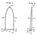
- Fig. 1 is a side elevation view of a mattress clip.
- Fig. 2 is an end elevation view of the mattress clip shown in Fig. 1.
- Fig. 3 is an elevation view of a mattress having the border strip removed and a portion of the fabric flanges of the mattress covers broken away to illustrate how the mattress clips secure the fabric flange to the adjacent coil springs.
- Fig.4 is an elevation view of a mattress showing the border strip with a zipper assembly along its upper edge to open the border strip for access to the inner parts of the mattress.
- Fig.5 is an elevation of a mattress showing the border strip with Velcro type fastening strips along and adjacent to the upper edge of the border strip.
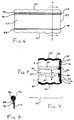
- Fig. 6 is an end elevation view of a modified mattress cover.
- Fig. 7 is a section view taken on line 7-7 of Fig. 6.
- Fig. 8 is a section view taken on line 8-8 of Fig. 7, but enlarged to more clearly show each of the component parts.
- Fig. 9 is an elevation view of a segment of the reinforcing cord received in the sleeve at the free end of the fabric flange to substantially eliminate the risk of a securing clip which secures the fabric flange to an adjacent spring from tearing loose.
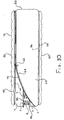
- Fig. 10 is a side elevation view of the modified mattress cover shown in place over an innerspring assembly with the zipper assembly partially open to show clips in place encompassing the reinforcing cord and sleeve around the free end of the fabric flange and secured to adjacent coils of the innerspring assembly.
- a mattress clip 2 is provided to secure the peripheral fabric flange 4 of the mattress cover 6 to individual coil springs 8 of the inner spring assembly 10 of a mattress 12.
- the mattress clip 2 comprises a continuous length of wire having a spring characteristic, such as steel wire, which has been bent or otherwise shaped into a first relatively short length 14 which extends laterally from a hook portion 16 at its free end 18 to a single loop portion 20.
- the single loop portion 20 is integrally joined to a second relatively longer length 22 which extends longitudinally in a direction substantially normal to the first relatively short length 14.
- the second relatively longer length 22 is about two inches long in a preferred embodiment and the first relatively shorter length 14 is about a quarter of an inch long, the second length 22 thereby being about eight times longer than the first length 14.
- the second relatively longer length 22 extends from the single loop portion 20 to a continuous double loop portion 24, integrally joined to the longer length 22 at one end of the double loop portion 24.
- the other end of the continuous double loop portion 24 is integrally joined to a third relatively long length 26 which is substantially the same length as the second relatively long length 22.
- the third long length 26 extends from its integral connection to the double loop portion 24 and terminates at its opposite free end 28 in a sharp point 30, which extends past the hook portion 16 and lies outwardly therefrom about an eighth of an inch in a preferred embodiment.
- the spring characteristic of the wire biases the free end 28 of the third long length 26 outwardly from the hook portion 16, but permits pressing the free end 28 toward the hook portion 16 and far enough past the hook portion to be directed into the entrance 32 of the hook portion 16 whereupon it closes the mattress clip 2 and holds it in its closed position.
- the mattress clip 2 is moved to its open position by pressing the free end 28 of the third long length 26 inwardly until it clears the entrance 32 of the hook portion 16 whereupon it springs back to its normally biased position outwardly from the hook portion 16.
- the mattress clip 22 makes it possible to more easily assemble a mattress, to the point that a mattress can be assembled by the average homeowner and others who have not had special training and experience in assembling mattresses.
- the present and prior art method of assembling mattresses uses hog rings in place of the mattress clip 2 special tool is needed to secure the fabric flange 4 of the quilted mattress cover 6 to the coil spring 8.
- an inner spring assembly 10 of the desired dimension is first obtained, having a plurality of coil springs 8. Then insulators of various types such as a wire or polypropylene mesh 34 and a natural or synthetic fiber pad 36 is placed on top of the innerspring assembly 10, the corners of which are secured to adjacent ones of the coil springs 8 by mattress clips 2.
- a polyurethane foam pad 38 is then placed on top of the insulators 34 and 36, whose corners are also secured to adjacent ones of the coil springs 8 by mattress clips 2.
- the mattress cover 6 having the peripheral fabric flange 4 is then placed on top of the polyurethane foam pad 38 with the peripheral flange 4 extending down around the periphery of the innerspring assembly 10.
- the peripheral flange 4 is then secured to each adjacent coil spring 8 around the periphery of the innerspring assembly 10 by mattress clips 2.
- the mattress clips 2 secure the fabric flange 4, as well as the insulators 34 and 36, and the polyurethane foam pad 38, to the coil springs 8 as follows.
- the third relatively long length 26 of the mattress clip 2 is placed on the inwardly facing side of the fabric flange 4, as well as of the insulators 34 and 36 and pad 38, with the sharp point 30 of its free end 28 in position to pierce through the fabric, then piercing through to the outwardly facing side, then piercing back through at a slightly spaced apart location to the inwardly facing side, then drawing the fabric snugly toward the adjacent coil spring 8, then positioning the entrance space 40 of the single loop portion 20, which spaces the facing end portions of the first short length 14 and second long length 22 of the mattress clip 2 apart, to receive the closest ring 42 of the adjacent coil spring 8 through the loop entrance space 40 to seat within the loop portion 20, then pressing the free end 28 of the third long length 26 toward and past the entrance 32 of the hook portion 16 and positioning it to enter the hook portion 16 thereby closing the mattress clip
- the loop entrance space 40 has a dimension which is slightly smaller than the cross-sectional dimension of the rings 42 of the helical coil springs 8.
- the end portions of the first short length 14 and second long length 22 which face each other across the entrance space 40 are resilient enough to spread apart sufficiently to allow the ring 42 of the coil spring 8 to pass into the loop portion 20, after which the facing portions of the short length 14 and long length 22 snap back to their original positions to thereby retain the ring 42 of the coil spring 8 within the loop portion 20.
- the partially assembled mattress is then turned over with the opposite side of the innerspring assembly 10 facing upwardly.
- the foregoing steps are then repeated, placing insulators 34 and 36 on top of that side of the innerspring assembly 10, securing the corners thereof to adjacent ones of the coil springs 8 using the mattress clips 2 as described above, then placing a polyurethane foam pad 38 on top of the insulators 34 and 36, securing the corners of the polyurethane pad 38 to adjacent ones of the coil springs 8, and finally placing a mattress cover 6 over the polyurethane foam pad 38 with its peripheral fabric flange 4 handing down around the periphery from that opposite side of the innerspring assembly 10, then securing such fabric flange 4 to each adjacent coil spring 8 around the periphery of the innerspring assembly 10 by using the mattress clips 2 as described.
- a peripheral border strip 44 of fabric material is secured around the peripheral side wall of the innerspring assembly 10 to cover and enclose the fabric flanges 4 of the mattress covers 6 placed on both the upwardly facing and downwardly facing sides of the innerspring assembly 10.
- the border strip 44 has an upper peripheral edge 46 which is adjacent to the outer peripheral edge 48 of the mattress cover panel 50 over the upwardly facing side of the innerspring assembly 10, and a lower peripheral edge 56 which is adjacent to the outer peripheral edge 58 of the mattress cover panel 60 over the downwardly facing side of the innerspring assembly 10.
- the lower peripheral edge 56 of the border strip 44 is sewn to the adjacent outer peripheral edge 58 of the mattress cover panel 60 which extends over the downwardly facing side of the innerspring assembly 10.
- the upper peripheral edge 46 of the border strip 44 is not sewn to the adjacent outer peripheral edge 48 of the mattress cover panel 50 which extends over the upwardly facing side of the innerspring assembly 10 in the method of assembling a mattress. Instead, an elongated zipper assembly 62 extends around the periphery of the innerspring assembly 10, having one of its peripheral securing strips 64 secured to the upper peripheral edge 46 of the border strip 44 and the other of its peripheral securing strips 66 secured to the outer peripheral edge 48 of the mattress cover panel 50.
- This construction makes it possible to removably secure the upper edge 46 of the border strip 44 to the mattress cover panel 50, by zipping up the zipper assembly 62 to secure the border strip 44 to the mattress cover panel 50 and by unzipping the zipper assembly 62 to detach the upper edge 46 of the border strip 44 from the peripheral outer edge 48 of the mattress cover panel 50 for access to the inner portions of the mattress.
- a Velcro type fastener 72 may be used.
- a peripheral strip of tiny flexible hook members 74 is secured to the upper peripheral edge 46 of the border strip 44 and a peripheral strip of tiny flexible loops 76 is secured to the outer peripheral edge 48 of the mattress cover panel 50.
- the peripheral strip 74 when placed against the peripheral strip 76 releasably connects the border strip 44 to the mattress cover panel 50 thereby closing the peripheral side wall of the mattress. It may be opened by pulling the peripheral strip 74 away from the peripheral strip 76.
- a modified mattress cover 80 is shown in Figures 6-10.
- the modified mattress cover 80 includes a top mattress cover panel 50 and a lower mattress cover panel 60, each having a fabric flange 4 around their periphery.
- the fabric flange 4 of mattress cover panel 50 is sewn thereto around the adjacent peripheral edge 82 of its fabric flange 4, and its fabric flange 4 extends downwardly from the top mattress cover panel 50.
- the fabric flange 4 of mattress cover panel 60 is sewn thereto around the adjacent peripheral edge 82 of its fabric flange 4, and its fabric flange 4 extends upwardly from the lower mattress cover panel 60.
- the fabric flange 4 has an opposite free edge 84 which extends around the periphery of the top mattress cover panel 50 and lower mattress cover panel 60 spaced apart from and substantially parallel to the adjacent peripheral edge 82 when the fabric flange is pulled taut.
- the peripheral free edge 84 of the fabric flange 4 is pulled taut when the flange 4 is to be secured to adjacent coil springs 8 of an innerspring assembly 10.
- the free edge 84 of the fabric flange 4 includes a peripheral sleeve 86 formed by a return portion 88 of the fabric sleeve folded over around its periphery, the outermost portion 90 of which is sewn to the facing portion of the fabric flange 4 leaving a peripheral loop portion 92 to form the peripheral sleeve 86.
- a peripheral cord 94 is threaded through the peripheral sleeve 86 which is open at each end in facing relationship with each other.
- the ends of the cord 94 extend outwardly from each end of the sleeve 86 and are brought together, bringing the corresponding ends of the sleeve 86 and of the fabric flange 4 together.
- the ends of the cord 94 are then tied.
- peripheral sleeve 86 and cord 94 provide a reinforced free edge portion around the periphery of the fabric flange 4 which the securing devices such as the mattress clip 2 can encompass or enfold when securing the peripheral edge of the fabric flange 4 to adjacent springs 8 of an innerspring assembly 10.
- the modified mattress cover 80 also includes a peripheral border strip 44 extending around its peripheral side wall.
- the lower peripheral edge 56 of the border strip 44 is sewn to the outer peripheral edge 58 of the lower mattress cover panel 60.
- a zipper assembly 62 extends around the periphery of the mattress cover between the outer peripheral edge 48 of the top mattress cover panel 50 and the upper peripheral edge 46 of the peripheral border strip 44.
- the top mattress cover panel 50 may be separated from the lower mattress cover panel 60 by unzipping the zipper assembly 62 for receiving an innerspring assembly 10 therebetween.
- each mattress cover panel is then secured to adjacent springs 8 by securing means such as the mattress pins 20 extending through the fabric inwardly from and adjacent the reinforcing peripheral sleeve 86 and peripheral cord 92, then around an adjacent coil of the adjacent spring 8, and fastening to secure each mattress cover panel to opposite sides of the innerspring assembly 10.
- the upper edge 46 of the border strip 44 is then brought together with the outer edge 48 of the top mattress cover panel at the starting end of the zipper assembly 62.
- the zipper is then zipped around the entire periphery to enclose the innerspring assembly 10 within the mattress cover 80.
- the reinforced peripheral free edge of the fabric flange 4 is not limited to use with mattress clip 2, but can be used with any means of securing the fabric to adjacent springs such as prior art clips known as hog rings, use of twine threaded through the fabric flange inwardly of the reinforced sleeve and cord free end and then tied to adjacent springs, and the like.
Landscapes
- Mattresses And Other Support Structures For Chairs And Beds (AREA)
Applications Claiming Priority (2)
| Application Number | Priority Date | Filing Date | Title |
|---|---|---|---|
| US25474094A | 1994-06-06 | 1994-06-06 | |
| US254740 | 1994-06-06 |
Publications (1)
| Publication Number | Publication Date |
|---|---|
| EP0686364A1 true EP0686364A1 (fr) | 1995-12-13 |
Family
ID=22965411
Family Applications (1)
| Application Number | Title | Priority Date | Filing Date |
|---|---|---|---|
| EP95303871A Withdrawn EP0686364A1 (fr) | 1994-06-06 | 1995-06-06 | Matelas |
Country Status (1)
| Country | Link |
|---|---|
| EP (1) | EP0686364A1 (fr) |
Cited By (3)
| Publication number | Priority date | Publication date | Assignee | Title |
|---|---|---|---|---|
| EP1674004A1 (fr) * | 2004-12-21 | 2006-06-28 | Espumas y Comercio de Pamplona, S. L. | Housse de matelas |
| CN112674536A (zh) * | 2019-10-17 | 2021-04-20 | 厦门新技术集成有限公司 | 用于家具的弹性模块和弹性垫 |
| JP2024532902A (ja) * | 2021-08-31 | 2024-09-10 | ニュー-テック インテグレーション (シアメン) カンパニー,リミテッド | 着脱可能な弾性クッション、家具及び組付方法 |
Citations (13)
| Publication number | Priority date | Publication date | Assignee | Title |
|---|---|---|---|---|
| US879232A (en) | 1905-04-27 | 1908-02-18 | Edward Young | Bale-tie fastener. |
| US1269660A (en) | 1916-08-12 | 1918-06-18 | Nettie V Turner | Tatting-hook and attaching means therefor. |
| US1608705A (en) | 1926-04-05 | 1926-11-30 | James L Macinerney | Clip |
| US1828012A (en) | 1930-07-03 | 1931-10-20 | Laura A Wragg | Drapery pin |
| US1875628A (en) | 1928-11-15 | 1932-09-06 | F A Neider Company | Tufting button |
| US2168076A (en) | 1938-02-16 | 1939-08-01 | Walenta Paul | Upholstery staple |
| US2224161A (en) | 1940-01-05 | 1940-12-10 | Rice William | Suspended type of support |
| US2287226A (en) | 1940-11-18 | 1942-06-23 | B And F Corp | Securing means |
| US2354848A (en) | 1941-09-27 | 1944-08-01 | Charles R Carpenter | Fish stringer and the like |
| US2556400A (en) | 1949-03-07 | 1951-06-12 | Fred J Schwartz | Wire drapery hanger |
| GB729835A (en) * | 1952-11-21 | 1955-05-11 | Slumberland Ltd | Improvements in or relating to spring-centre mattresses |
| US3055021A (en) * | 1960-03-29 | 1962-09-25 | Murray J Rymland | Upholstered spring assembly |
| DE8908352U1 (de) * | 1989-07-08 | 1989-10-19 | Paradies GmbH Gebr. Kremers, 4133 Neukirchen-Vluyn | Bettpolster |
-
1995
- 1995-06-06 EP EP95303871A patent/EP0686364A1/fr not_active Withdrawn
Patent Citations (13)
| Publication number | Priority date | Publication date | Assignee | Title |
|---|---|---|---|---|
| US879232A (en) | 1905-04-27 | 1908-02-18 | Edward Young | Bale-tie fastener. |
| US1269660A (en) | 1916-08-12 | 1918-06-18 | Nettie V Turner | Tatting-hook and attaching means therefor. |
| US1608705A (en) | 1926-04-05 | 1926-11-30 | James L Macinerney | Clip |
| US1875628A (en) | 1928-11-15 | 1932-09-06 | F A Neider Company | Tufting button |
| US1828012A (en) | 1930-07-03 | 1931-10-20 | Laura A Wragg | Drapery pin |
| US2168076A (en) | 1938-02-16 | 1939-08-01 | Walenta Paul | Upholstery staple |
| US2224161A (en) | 1940-01-05 | 1940-12-10 | Rice William | Suspended type of support |
| US2287226A (en) | 1940-11-18 | 1942-06-23 | B And F Corp | Securing means |
| US2354848A (en) | 1941-09-27 | 1944-08-01 | Charles R Carpenter | Fish stringer and the like |
| US2556400A (en) | 1949-03-07 | 1951-06-12 | Fred J Schwartz | Wire drapery hanger |
| GB729835A (en) * | 1952-11-21 | 1955-05-11 | Slumberland Ltd | Improvements in or relating to spring-centre mattresses |
| US3055021A (en) * | 1960-03-29 | 1962-09-25 | Murray J Rymland | Upholstered spring assembly |
| DE8908352U1 (de) * | 1989-07-08 | 1989-10-19 | Paradies GmbH Gebr. Kremers, 4133 Neukirchen-Vluyn | Bettpolster |
Cited By (5)
| Publication number | Priority date | Publication date | Assignee | Title |
|---|---|---|---|---|
| EP1674004A1 (fr) * | 2004-12-21 | 2006-06-28 | Espumas y Comercio de Pamplona, S. L. | Housse de matelas |
| CN112674536A (zh) * | 2019-10-17 | 2021-04-20 | 厦门新技术集成有限公司 | 用于家具的弹性模块和弹性垫 |
| CN112674541A (zh) * | 2019-10-17 | 2021-04-20 | 厦门新技术集成有限公司 | 用于家具的弹性模块和弹性垫 |
| CN112674536B (zh) * | 2019-10-17 | 2024-08-02 | 厦门新技术集成有限公司 | 用于家具的弹性模块和弹性垫 |
| JP2024532902A (ja) * | 2021-08-31 | 2024-09-10 | ニュー-テック インテグレーション (シアメン) カンパニー,リミテッド | 着脱可能な弾性クッション、家具及び組付方法 |
Similar Documents
| Publication | Publication Date | Title |
|---|---|---|
| US5644811A (en) | Mattress having access to materials sandwiched between mattress cover and inner cushioning assembly | |
| US5435026A (en) | Mattress clip and mattress | |
| US5894664A (en) | Seating suspension assembly formation method | |
| US5072470A (en) | Device for holding bedclothes in a fixed position on a bed | |
| US6709054B2 (en) | Slipcover wrapping technique | |
| US6631538B1 (en) | Self-closing clasp assembly | |
| US10681997B1 (en) | Couch blanket | |
| US20060065281A1 (en) | Hairpiece with attachment rings and kit for attaching hairpiece | |
| US5325554A (en) | Retainer for bedclothes | |
| CA2136524A1 (fr) | Dispositif pour coiffer les cheveux | |
| US11109698B1 (en) | Pillowcase whose internal cavity accommodates an open pocket into which is fitted a neck support cushion | |
| US20190328144A1 (en) | Double Mattress Connecting System | |
| CA2657289C (fr) | Boucle de retenue de matelas | |
| WO2006044245A2 (fr) | Matelas comportant une enveloppe en mousse, et son procede de production | |
| EP1269895A2 (fr) | Berceau pliable pour bebes | |
| WO1989003650A1 (fr) | Bordure anti-poussiere froncee pour lit | |
| US6233760B1 (en) | Box spring with padded cover | |
| US5768726A (en) | Mattress spring core assembly cover | |
| US5857231A (en) | Hammock cover | |
| US6557194B1 (en) | Method for securing bed coverings and apparatus therefor | |
| US5432964A (en) | Field serviceable mattress and method for manufacture | |
| US2697863A (en) | Pin fastener for furniture covers and the like | |
| US6088859A (en) | Mattress assembly with releasable border strip | |
| US3995337A (en) | Mattress construction | |
| CA2143089A1 (fr) | Clip pour matelas; le matelas correspondant |
Legal Events
| Date | Code | Title | Description |
|---|---|---|---|
| PUAI | Public reference made under article 153(3) epc to a published international application that has entered the european phase |
Free format text: ORIGINAL CODE: 0009012 |
|
| AK | Designated contracting states |
Kind code of ref document: A1 Designated state(s): AT BE CH DE DK ES FR GB GR IE IT LI LU MC NL PT SE |
|
| RAX | Requested extension states of the european patent have changed |
Free format text: LT PAYMENT 950620;LV PAYMENT 950620;SI PAYMENT 950620 |
|
| STAA | Information on the status of an ep patent application or granted ep patent |
Free format text: STATUS: THE APPLICATION IS DEEMED TO BE WITHDRAWN |
|
| 18D | Application deemed to be withdrawn |
Effective date: 19960614 |