EP0686370B1 - Saugvorrichtung - Google Patents
Saugvorrichtung Download PDFInfo
- Publication number
- EP0686370B1 EP0686370B1 EP95106893A EP95106893A EP0686370B1 EP 0686370 B1 EP0686370 B1 EP 0686370B1 EP 95106893 A EP95106893 A EP 95106893A EP 95106893 A EP95106893 A EP 95106893A EP 0686370 B1 EP0686370 B1 EP 0686370B1
- Authority
- EP
- European Patent Office
- Prior art keywords
- air
- opening
- suction
- air intake
- intake opening
- Prior art date
- Legal status (The legal status is an assumption and is not a legal conclusion. Google has not performed a legal analysis and makes no representation as to the accuracy of the status listed.)
- Expired - Lifetime
Links
- 238000005452 bending Methods 0.000 claims 3
- 238000002347 injection Methods 0.000 claims 3
- 239000007924 injection Substances 0.000 claims 3
- 239000003570 air Substances 0.000 description 72
- 230000000694 effects Effects 0.000 description 5
- 239000000463 material Substances 0.000 description 3
- 239000012080 ambient air Substances 0.000 description 2
- 238000007664 blowing Methods 0.000 description 2
- 238000010408 sweeping Methods 0.000 description 2
- 244000037795 Pachira macrocarpa Species 0.000 description 1
- 238000001514 detection method Methods 0.000 description 1
- 238000000605 extraction Methods 0.000 description 1
- 230000001737 promoting effect Effects 0.000 description 1
Images
Classifications
-
- E—FIXED CONSTRUCTIONS
- E01—CONSTRUCTION OF ROADS, RAILWAYS, OR BRIDGES
- E01H—STREET CLEANING; CLEANING OF PERMANENT WAYS; CLEANING BEACHES; DISPERSING OR PREVENTING FOG IN GENERAL CLEANING STREET OR RAILWAY FURNITURE OR TUNNEL WALLS
- E01H1/00—Removing undesirable matter from roads or like surfaces, with or without moistening of the surface
- E01H1/08—Pneumatically dislodging or taking-up undesirable matter or small objects; Drying by heat only or by streams of gas; Cleaning by projecting abrasive particles
- E01H1/0809—Loosening or dislodging by blowing ; Drying by means of gas streams
-
- A—HUMAN NECESSITIES
- A47—FURNITURE; DOMESTIC ARTICLES OR APPLIANCES; COFFEE MILLS; SPICE MILLS; SUCTION CLEANERS IN GENERAL
- A47L—DOMESTIC WASHING OR CLEANING; SUCTION CLEANERS IN GENERAL
- A47L9/00—Details or accessories of suction cleaners, e.g. mechanical means for controlling the suction or for effecting pulsating action; Storing devices specially adapted to suction cleaners or parts thereof; Carrying-vehicles specially adapted for suction cleaners
- A47L9/02—Nozzles
- A47L9/08—Nozzles with means adapted for blowing
-
- E—FIXED CONSTRUCTIONS
- E01—CONSTRUCTION OF ROADS, RAILWAYS, OR BRIDGES
- E01H—STREET CLEANING; CLEANING OF PERMANENT WAYS; CLEANING BEACHES; DISPERSING OR PREVENTING FOG IN GENERAL CLEANING STREET OR RAILWAY FURNITURE OR TUNNEL WALLS
- E01H1/00—Removing undesirable matter from roads or like surfaces, with or without moistening of the surface
- E01H1/08—Pneumatically dislodging or taking-up undesirable matter or small objects; Drying by heat only or by streams of gas; Cleaning by projecting abrasive particles
- E01H2001/0881—Details for pneumatically dislodging or removing not related to the mouth-piece
- E01H2001/089—Suction-effect created through blowing, e.g. using the venturi effect
Definitions
- the present invention has a suction device with a Air intake opening and an air outlet opening Suction pipe to the object in the area of its air intake one connected to a pressure source, directed in the suction direction Has injector opening from the primary air into the Intake pipe flows, being in the area of the air intake opening there is an additional air inlet opening in the intake manifold.
- EP-A-0 587 272 is a suction device with a Air intake opening and an air outlet opening Suction pipe known.
- This suction pipe has in the area of its air intake opening one connected to a pressure source, in the suction direction open inlet opening, from the primary air into the Intake pipe flows.
- Located in the area of the air intake an additional air inlet opening in the intake manifold the ambient air is drawn into the intake manifold.
- the suction device attached to the floor flows into the ambient air same direction as the primary air flowing into the intake manifold the suction pipe.
- the opening cross-section is the inlet opening chosen so large that it covers the entire opening cross-section of the suction pipe near the suction opening as possible uniform secondary air flow, i.e.
- the object of the present invention is therefore in a suction device of the type mentioned the suction effect for relative to improve heavy objects.
- Air inlet opening can be a "sweeping" for difficult ones promoting suction material in the direction of the injector nozzle and thus in the direction stronger suction effect. This allows in the Objects located away from primary air through the secondary air flowing in the additional air inlet opening "turned" to the high-energy air conveyor belt and close to the primary air Area of the intake opening.
- This additional air intake opening can, for example through a hole in the wall of the suction pipe, Recess or the like. Be formed.
- this becomes additional Air intake opening by angling the front edge the plane defining the air intake opening, then this bend expediently to an edge area of this limited by the face edge of the air intake opening is.
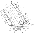
- the attached drawing shows the longitudinal section of the bottom End 1 of a suction device not shown associated suction pipe 2, the air intake opening designated 3 is.
- This suction pipe 2 is with two axially directed Air channels 4 and 5 equipped, in the direction of the arrows 6 and 7 of one belonging to the suction device and also Air pressure source not particularly shown compressed air supplied becomes.
- the air duct 4 has an injector nozzle 8 through which the primary air supplied through this air duct 4 in the direction of arrow 9 and thus approximately in the suction direction 10 blown into the interior 11 of the suction pipe 2 and so through the air intake opening 3 entering the intake pipe 2 secondary air 12 is carried away.
- Air duct 5 leaves and in the direction of arrows 14 to the 15th designated floor.
Landscapes
- Engineering & Computer Science (AREA)
- Mechanical Engineering (AREA)
- Architecture (AREA)
- Civil Engineering (AREA)
- Structural Engineering (AREA)
- Jet Pumps And Other Pumps (AREA)
- Ventilation (AREA)
- Manipulator (AREA)
- Branching, Merging, And Special Transfer Between Conveyors (AREA)
- Massaging Devices (AREA)
- Cleaning In General (AREA)
Description
Claims (5)
- Saugvorrichtung mit einem eine Luftansaugöffnung (3) und eine Luftaustrittsöffnung aufweisenden Saugrohr (2), das im Bereich seiner Luftansaugöffnung (3) eine mit einer Druckquelle verbundene, in der Saugrichtung (10) gerichtete Injektoröffnung aufweist, aus der Primärluft in das Saugrohr (2) einströmt, wobei sich im Bereich der Luftansaugöffnung (3) in dem Saugrohr (2) eine zusätzliche Lufteintrittsöffnung (20) befindet, dadurch gekennzeichnet, daß die zusätzliche Lufteintrittsöffnung (20) gegenüberliegen der als Injektordüse (8) ausgebildeten Injektoröffnung angeordnet ist.
- Saugvorrichtung nach Anspruch 1, dadurch gekennzeichnet, daß die die zusätzliche Luftansaugöffnung durch eine in der Wandung des Saugrohres (2) eingebrachte Bohrung, Aussparung od. dgl. gebildet ist.
- Saugvorrichtung nach Anspruch 1, dadurch gekennzeichnet, daß die zusätzliche Luftansaugöffnung (20) durch eine Abwinkelung (x) der die Stirnkante (16) der Luftansaugöffnung (3) begrenzenden Ebene (17) gebildet ist.
- Saugvorrichtung nach Anspruch 3, dadurch gekennzeichnet, daß die Abwinkelung (x) der die Stirnkante (16) der Luftansaugöffnung (3) begrenzenden Ebene (17) auf einen Randbereich (23) derselben begrenzt ist.
- Saugvorrichtung nach einem oder mehreren der Ansprüche 1 bis 4 mit einem mit einer Druckluftquelle verbundenen Blasluft zuführenden Luftkanal, dadurch gekennzeichnet, daß sich die Abwinkelung (x) der die Stirnkante (16) der Luftabsaugöffnung (3) begrenzenden Ebene (17) im Bereich der Luftaustrittsöffnung (13) des Blasluftkanals (5) befindet, dessen dem Saugrohrinneren zugekehrte Innenwand (22) zur Bildung einer Luftdurchtrittsöffnung (24) gegenüber der Stirnkante (33) der Luftansaugöffnung (3) um das Maß (a) in das Rohr innere versetzt ist.
Applications Claiming Priority (2)
| Application Number | Priority Date | Filing Date | Title |
|---|---|---|---|
| DE9409086U DE9409086U1 (de) | 1994-06-03 | 1994-06-03 | Saugvorrichtung |
| DE9409086U | 1994-06-03 |
Publications (2)
| Publication Number | Publication Date |
|---|---|
| EP0686370A1 EP0686370A1 (de) | 1995-12-13 |
| EP0686370B1 true EP0686370B1 (de) | 1999-02-24 |
Family
ID=6909447
Family Applications (1)
| Application Number | Title | Priority Date | Filing Date |
|---|---|---|---|
| EP95106893A Expired - Lifetime EP0686370B1 (de) | 1994-06-03 | 1995-05-06 | Saugvorrichtung |
Country Status (3)
| Country | Link |
|---|---|
| EP (1) | EP0686370B1 (de) |
| CN (1) | CN1067872C (de) |
| DE (2) | DE9409086U1 (de) |
Cited By (1)
| Publication number | Priority date | Publication date | Assignee | Title |
|---|---|---|---|---|
| WO2007118266A1 (en) * | 2005-11-16 | 2007-10-25 | Paul Frederick Finster | Hand held spray and pump device |
Families Citing this family (14)
| Publication number | Priority date | Publication date | Assignee | Title |
|---|---|---|---|---|
| DE4423197A1 (de) * | 1994-07-01 | 1996-01-04 | Gema Volstatic Ag | Pulverpumpe, insbesondere für Pulver zum Sprühbeschichten von Gegenständen |
| DE19524203C2 (de) * | 1994-12-13 | 1999-07-29 | Haller Umweltsysteme Gmbh & Co | Kehrmaschine mit Staubabsaugung |
| GB2296026B8 (en) * | 1994-12-13 | 1999-07-06 | Haller Umweltsysteme Gmbh & Co | Sweeping machine with dust extraction |
| DE19531442C3 (de) * | 1995-08-26 | 2001-04-26 | Multi Cad Gmbh | Aufnahmevorrichtung |
| DE19949786A1 (de) * | 1999-10-15 | 2001-04-19 | Anton Jaeger | Sauger für Hochdruckreiniger |
| US6735814B2 (en) | 2000-10-05 | 2004-05-18 | Mister Services, Inc. | Apparatus for cleaning hard-to-reach areas |
| FR2867052A1 (fr) * | 2004-03-02 | 2005-09-09 | David Sadaune | Dispositif de nettoyage par aspiration comprenant des moyens de soufflage |
| DE102012107051B4 (de) * | 2012-08-01 | 2022-11-10 | Spifeltec Ug | Reinigungsgerät |
| CN102836600A (zh) * | 2012-09-04 | 2012-12-26 | 云南智奇工程技术有限公司 | 高压远程除尘清灰器 |
| CN102888725B (zh) * | 2012-09-22 | 2014-08-06 | 新杰克缝纫机股份有限公司 | 平缝机之吸线毛装置 |
| CN104074157B (zh) * | 2013-03-29 | 2016-02-10 | 南京德朔实业有限公司 | 手持式吹风机 |
| JP6116629B2 (ja) * | 2015-08-11 | 2017-04-19 | 株式会社ハーモテック | 吸引装置 |
| CN107059728B (zh) * | 2017-05-05 | 2023-06-16 | 启迪合加新能源汽车有限公司 | 一种洗扫车的吸嘴用导管专用装置 |
| CN107858976B (zh) * | 2017-11-14 | 2023-12-05 | 江苏徐工国重实验室科技有限公司 | 清洁车吸嘴及具有其的清洁车 |
Family Cites Families (5)
| Publication number | Priority date | Publication date | Assignee | Title |
|---|---|---|---|---|
| CH397983A (de) * | 1961-10-31 | 1965-08-31 | Siemens Elektrogeraete Gmbh | Staubsaugerdüse mit an der Unterseite der Düse vorgesehenem Kamm zur Aufnahme von Fäden |
| US4018483A (en) * | 1974-09-18 | 1977-04-19 | Smith D Kermit | Process and apparatus for dislodging and conveying material from a surface with a positive pressure fluid stream |
| GB2179099B (en) * | 1985-08-12 | 1989-07-26 | Vacuum Pneumatic Transfer Equi | Vacuum aerator feed nozzle |
| US4649594A (en) * | 1985-10-18 | 1987-03-17 | Grave Dale L | Cleaning head for smooth and napped surface covering materials |
| GB9219330D0 (en) * | 1992-09-11 | 1992-10-28 | Electrolux Northern | Improvements in and relating to collection devices |
-
1994
- 1994-06-03 DE DE9409086U patent/DE9409086U1/de not_active Expired - Lifetime
-
1995
- 1995-05-06 DE DE59505135T patent/DE59505135D1/de not_active Expired - Fee Related
- 1995-05-06 EP EP95106893A patent/EP0686370B1/de not_active Expired - Lifetime
- 1995-06-02 CN CN95107178A patent/CN1067872C/zh not_active Expired - Fee Related
Cited By (1)
| Publication number | Priority date | Publication date | Assignee | Title |
|---|---|---|---|---|
| WO2007118266A1 (en) * | 2005-11-16 | 2007-10-25 | Paul Frederick Finster | Hand held spray and pump device |
Also Published As
| Publication number | Publication date |
|---|---|
| DE59505135D1 (de) | 1999-04-01 |
| CN1067872C (zh) | 2001-07-04 |
| CN1120129A (zh) | 1996-04-10 |
| DE9409086U1 (de) | 1994-07-28 |
| EP0686370A1 (de) | 1995-12-13 |
Similar Documents
| Publication | Publication Date | Title |
|---|---|---|
| DE4425863C2 (de) | Saug- und Blasvorrichtung | |
| DE60204177T2 (de) | Mechanismus zum Wechseln der Luftströmungsrichtung einer Blas-/Saugvorrichtung | |
| DE102004058776B3 (de) | Vorrichtung zur Belüftung einer Rotornabe einer Windenergieanlage | |
| DE2805017A1 (de) | Vorrichtung zum trennen bzw. ausscheiden von bestandteilen eines gutes der tabakverarbeitenden industrie aus luft | |
| DE69320905T2 (de) | Sammelvorrichtung | |
| EP0686370A1 (de) | Saugvorrichtung | |
| DE3109154C2 (de) | Vorrichtung zum Abscheiden von Fremdkörpern, insbesondere Schwerteilen wie Metall-, Holz- und Pappteilen o.dgl. aus Baumwollfaserflocken | |
| WO2016134397A1 (de) | Pneumatische fördereinrichtung und dosieranlage sowie sandungsanlage mit einer strahlpumpe für rieselfähiges gut | |
| DE4319726A1 (de) | Pulverfördereinrichtung | |
| DE19824802A1 (de) | Pulverförder-Injektor | |
| DE3238110A1 (de) | Arbeitstisch, insbesondere schweisstisch, mit einer absaugeinrichtung | |
| EP0392455B1 (de) | Reinigungsmaschine | |
| DE2443033A1 (de) | Saug-mischkopf | |
| DE19946564C2 (de) | Nassfilter für ein Bodenreinigungsgerät | |
| DE1154252B (de) | Abschirmung von Raumoeffnungen durch einen Luftschleier | |
| EP1935504A2 (de) | Vorrichtung zur Reinigung einer Pulverbeschichtungskabine und Pulverbeschichtungskabine mit Reinigungsvorrichtung | |
| DE3423877C2 (de) | ||
| DE10227604B4 (de) | Anordnung, welche einen Kraftstofftank eines Kraftfahrzeugs, eine Versorgungseinrichtung und wenigstens eine Anschlussvor-richtung zum Anschließen des Endes eines Kraftstoffzuleitungs-rohres an die Öffnung der Versorgungseinrichtung umfasst | |
| DE2631549A1 (de) | Trichterfoermige lufteinblasvorrichtung mit einstellbarem durchsatz | |
| DE9208718U1 (de) | Bauelement einer Lüftungsinstallation | |
| DE29610752U1 (de) | Saugvorrichtung | |
| DE7609105U1 (de) | Mit saugluft arbeitendes aufnahmegeraet fuer staub oder dergleichen | |
| DE4427149C1 (de) | Bohrwerkzeug, insbesondere für Bohrhämmer | |
| EP0816769A3 (de) | Umluft-Betriebsvorrichtung für ein Zwangslüftungsgerät | |
| DE3440910A1 (de) | Staubsauger mit einem klappbaren deckel fuer zubehoerteile |
Legal Events
| Date | Code | Title | Description |
|---|---|---|---|
| PUAI | Public reference made under article 153(3) epc to a published international application that has entered the european phase |
Free format text: ORIGINAL CODE: 0009012 |
|
| AK | Designated contracting states |
Kind code of ref document: A1 Designated state(s): DE GB IT |
|
| 17P | Request for examination filed |
Effective date: 19960521 |
|
| 17Q | First examination report despatched |
Effective date: 19970904 |
|
| GRAG | Despatch of communication of intention to grant |
Free format text: ORIGINAL CODE: EPIDOS AGRA |
|
| GRAG | Despatch of communication of intention to grant |
Free format text: ORIGINAL CODE: EPIDOS AGRA |
|
| GRAH | Despatch of communication of intention to grant a patent |
Free format text: ORIGINAL CODE: EPIDOS IGRA |
|
| GRAH | Despatch of communication of intention to grant a patent |
Free format text: ORIGINAL CODE: EPIDOS IGRA |
|
| GRAA | (expected) grant |
Free format text: ORIGINAL CODE: 0009210 |
|
| AK | Designated contracting states |
Kind code of ref document: B1 Designated state(s): DE GB IT |
|
| REF | Corresponds to: |
Ref document number: 59505135 Country of ref document: DE Date of ref document: 19990401 |
|
| ITF | It: translation for a ep patent filed | ||
| GBT | Gb: translation of ep patent filed (gb section 77(6)(a)/1977) |
Effective date: 19990512 |
|
| PLBE | No opposition filed within time limit |
Free format text: ORIGINAL CODE: 0009261 |
|
| STAA | Information on the status of an ep patent application or granted ep patent |
Free format text: STATUS: NO OPPOSITION FILED WITHIN TIME LIMIT |
|
| 26N | No opposition filed | ||
| REG | Reference to a national code |
Ref country code: GB Ref legal event code: IF02 |
|
| PGFP | Annual fee paid to national office [announced via postgrant information from national office to epo] |
Ref country code: IT Payment date: 20080520 Year of fee payment: 14 |
|
| PGFP | Annual fee paid to national office [announced via postgrant information from national office to epo] |
Ref country code: DE Payment date: 20080703 Year of fee payment: 14 |
|
| PGFP | Annual fee paid to national office [announced via postgrant information from national office to epo] |
Ref country code: GB Payment date: 20080415 Year of fee payment: 14 |
|
| GBPC | Gb: european patent ceased through non-payment of renewal fee |
Effective date: 20090506 |
|
| PG25 | Lapsed in a contracting state [announced via postgrant information from national office to epo] |
Ref country code: GB Free format text: LAPSE BECAUSE OF NON-PAYMENT OF DUE FEES Effective date: 20090506 |
|
| PG25 | Lapsed in a contracting state [announced via postgrant information from national office to epo] |
Ref country code: DE Free format text: LAPSE BECAUSE OF NON-PAYMENT OF DUE FEES Effective date: 20091201 |
|
| PG25 | Lapsed in a contracting state [announced via postgrant information from national office to epo] |
Ref country code: IT Free format text: LAPSE BECAUSE OF NON-PAYMENT OF DUE FEES Effective date: 20090506 |