EP0686416A2 - Verschiebevorrichtung für Filterplatten an einer Filterpresse - Google Patents
Verschiebevorrichtung für Filterplatten an einer Filterpresse Download PDFInfo
- Publication number
- EP0686416A2 EP0686416A2 EP95108664A EP95108664A EP0686416A2 EP 0686416 A2 EP0686416 A2 EP 0686416A2 EP 95108664 A EP95108664 A EP 95108664A EP 95108664 A EP95108664 A EP 95108664A EP 0686416 A2 EP0686416 A2 EP 0686416A2
- Authority
- EP
- European Patent Office
- Prior art keywords
- chain
- carriage
- guide rail
- filter
- tab
- Prior art date
- Legal status (The legal status is an assumption and is not a legal conclusion. Google has not performed a legal analysis and makes no representation as to the accuracy of the status listed.)
- Granted
Links
- 238000006073 displacement reaction Methods 0.000 description 6
- 238000012423 maintenance Methods 0.000 description 2
- 229920002430 Fibre-reinforced plastic Polymers 0.000 description 1
- 229910000831 Steel Inorganic materials 0.000 description 1
- 238000011161 development Methods 0.000 description 1
- 230000018109 developmental process Effects 0.000 description 1
- 239000011151 fibre-reinforced plastic Substances 0.000 description 1
- 239000004033 plastic Substances 0.000 description 1
- 229920003023 plastic Polymers 0.000 description 1
- 230000001681 protective effect Effects 0.000 description 1
- 239000010959 steel Substances 0.000 description 1
Images

Classifications
-
- B—PERFORMING OPERATIONS; TRANSPORTING
- B01—PHYSICAL OR CHEMICAL PROCESSES OR APPARATUS IN GENERAL
- B01D—SEPARATION
- B01D25/00—Filters formed by clamping together several filtering elements or parts of such elements
- B01D25/12—Filter presses, i.e. of the plate or plate and frame type
- B01D25/172—Plate spreading means
Definitions
- the invention relates to a displacement device according to the preamble of claim 1.
- the invention is therefore based on the object to ensure in a sliding device of the type mentioned that the chain is safely guided in the chain channel and yet easy to dismantle for maintenance work.
- the filter press shown in FIG. 1 has a top plate 10 and an end plate 12, which are arranged parallel to one another perpendicularly in the usual way and are connected to one another by a pair of horizontal bars 14.
- the cylinder of a hydraulic piston-cylinder unit 16 is attached to the end plate 12.
- a plurality of filter plates 20 are arranged between the sliding plate 18 and the head plate 10, each of which is guided on the spars 14 with two lateral projections 22 formed on them.
- a displacement device for the filter plates 20 is assigned to each of the two spars 14.
- the two shifting devices are mirrored; therefore only one of them is shown in the drawings and described below.
- It includes a guide rail 24, which consists, for example, of fiber-reinforced plastic, extends parallel to the neighboring spar 14 and is fastened to the outside thereof.
- a chain channel 26 is formed in the guide rail 24 and opens downwards with a longitudinal slot 28.
- a slide 30 is guided on the guide rail 24 and has a U- shaped upper part 32 in the example shown and an inverted L- shaped lower part 34.
- the guide rail 24 and that Upper part 32 of the slide 30 are designed symmetrically with respect to a vertical plane of symmetry S parallel to the longitudinal center plane of the filter press.
- two drivers 36 and 38 are pivotally mounted and pretensioned in such a way that they endeavor, in the manner shown, to engage one of the filter plates 20 behind the lateral projection 22 protruding beyond the guide rail 24, in order to engage the filter plate in question with another one Carrying stroke of the carriage 30.
- This is done on both sides of the filter press in the same way by the carriage 30 of both displacement devices; as a result, the filter plates 20 remain constantly parallel to the head plate 10 during their movement.
- a chain 40 is guided in the chain channel 26, which is a Gall link plate chain according to FIGS. 2 and 3, but a round link chain according to FIGS. 4 and 5.
- the profile of the chain channel 26 is closely matched to the profile of the chain 40 so that it is securely guided in the guide rail 24.
- the chain 40 is guided only with its upper run in the guide rail 24 and runs outside of it via a drive device 42 at the right end of the filter press in FIG. 1 and via a deflection device 44 at its left end.
- the lower strand of the chain 40 in the example shown is guided in a cylindrical protective tube 46, which can also consist of plastic.
- the chain 40 has two ends in the area of the carriage 30, in the example shown below it, which are connected to one another only in that the chain links 48 arranged there are connected to one another by a link 50.
- the tab 50 is a comb-like, flat steel plate with at least two teeth 52, which each engage in a chain link 48 at the two ends of the chain 40. So that the chain hoist is better distributed over the link 50, this has a total of eight teeth 52 according to FIG. 3 and also FIG. 5, of which four teeth are assigned to the two chain ends.
- the tab 50 is releasably attached to the carriage 30.
- the tab 50 has two elongated holes 54 parallel to the longitudinal direction of the chain 40, through which it is screwed onto the lower part 34 of the carriage 30, the tab 50 being clamped between two clamping strips 56 and 58.
- the clamping strip 56 is arranged between the lower part 34 and the tab 50 and its thickness is such that the vertical longitudinal center plane of the tab 50 coincides with the plane of symmetry S.
- the clamping strip 58 has threaded holes 60 for a total of four clamping screws 62 in the example shown, to which through holes in the lower part 34 of the slide 30 and in the clamping strip 56 are assigned.
- the two terminal strips 56 and 58 are at the same time guide strips which prevent the slide 30 from lifting off or jamming from the guide rail 24.
- the tab 50 and the terminal strips 56 and 58 can be easily removed by removing the screws 62. Subsequently, the carriage 30 can be easily pulled off the guide rail 24 vertically, in the example shown upwards.
- the displacement device shown is also suitable for filter presses with filter plates suspended centrally on a support. It may be expedient to fasten the displacement device, or two of them, to the carrier in an arrangement which is the reverse of the illustrated exemplary embodiments, that is to say with an upwardly open longitudinal slot 28 through which the tab 50 protrudes upward.
Landscapes
- Chemical & Material Sciences (AREA)
- Chemical Kinetics & Catalysis (AREA)
- Filtration Of Liquid (AREA)
- Disintegrating Or Milling (AREA)
Abstract
Description
- Die Erfindung betrifft eine Verschiebevorrichtung nach dem Oberbegriff des Anspruchs 1.
- Bei Verschiebevorrichtungen dieser Gattung, wie sie beispielsweise aus der EP 0 453 342 A1 bekannt sind, besteht das Problem, daß die Kette zwar in sich geschlossen sein muß, damit nur an einem Ende der Filterpresse eine Antriebsvorrichtung für die Kette erforderlich ist, daß aber ein Kettenschloß üblicher Art nur verwendet werden kann, wenn der Kettenkanal entsprechend breit ist, was aber den Nachteil hat, daß die Kette sich im Kettenkanal schrägstellen oder gar verkanten kann, wodurch erheblicher Verschleiß entsteht. Es ist deshalb üblich, siehe z.B. die US 33 06 455, die Kette im Bereich des Schlittens zu unterbrechen und ihre beiden Enden je für sich am Schlitten zu befestigen, was aber umständlich ist.
- Der Erfindung liegt deshalb die Aufgabe zugrunde, bei einer Verschiebevorrichtung der genannten Gattung dafür zu sorgen, daß die Kette im Kettenkanal sicher geführt und dennoch für Wartungsarbeiten leicht demontierbar ist.
- Die Aufgabe ist erfindungsgemäß mit den Merkmalen des Anspruchs 1 gelöst. Weiterbildungen der Erfindung ergeben sich aus den Unteransprüchen.
- Ausführungsbeispiele der Erfindung werden im folgenden anhand schematischer Zeichnungen mit weiteren Einzelheiten erläutert. Es zeigen:
- Fig. 1
- eine Filterpresse mit einer erfindungsgemäßen Verschiebevorrichtung in Seitenansicht,
- Fig. 2
- den Teilquerschnitt II-II in Fig.1,
- Fig. 3
- den Teillängsschnitt III-III in Fig.2,
- Fig. 4
- einen der Fig. 2 entsprechenden Teilquerschnitt einer abgewandelten Ausführungsform der Erfindung und
- Fig. 5
- den Teillängsschnitt V-V in Fig. 4.
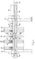
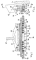
- Die in Fig. 1 dargestellte Filterpresse hat eine Kopfplatte 10 und eine Endplatte 12, die in üblicher Weise paralell zueinander senkrecht angeordnet und durch ein Paar waagerechte Holme 14 miteinander verbunden sind. An der Endplatte 12 ist der Zylinder einer hydraulischen Kolbenzylindereinheit 16 befestigt. Auf den Holmen 14 ist eine zur Kopfplatte 10 und Endplatte 12 parallele Schiebeplatte 18 geführt, an der die Kolbenstange der Kolbenzylindereinheit 16 befestigt ist. Zwischen der Schiebeplatte 18 und der Kopfplatte 10 ist eine Vielzahl Filterplatten 20 angeordnet, die mit je zwei an ihnen ausgebildeten seitlichen Vorsprüngen 22 auf den Holmen 14 geführt sind.
- Den beiden Holmen 14 ist je eine Verschiebevorrichtung für die Filterplatten 20 zugeordnet. Die beiden Verschiebevorrichtungen sind spiegelgleich; deshalb wird nur eine von ihnen in den Zeichnungen dargestellt und im folgenden beschrieben. Zu ihr gehört eine Führungsschiene 24, die beispielsweise aus faserverstärktem Kunststoff besteht, sich parallel zum benachbarten Holm 14 erstreckt und an dessen Außenseite befestigt ist. In der Führungsschiene 24 ist ein Kettenkanal 26 ausgebildet, der sich mit einem Längsschlitz 28 nach unten öffnet. Auf der Führungsschiene 24 ist ein Schlitten 30 geführt, der ein im dargestellten Beispiel U-förmiges Oberteil 32 und ein umgekehrt L-förmiges Unterteil 34 aufweist. Die Führungsschiene 24 sowie das Oberteil 32 des Schlittens 30 sind in bezug auf eine senkrechte, zur Längsmittelebene der Filterpresse parallele Symmetrieebene S symmetrisch gestaltet.
- Am Oberteil 32 des Schlittens 30 sind zwei Mitnehmer 36 und 38 schwenkbar gelagert und derart vorgespannt, daß sie bestrebt sind, in der dargestellten Weise hinter dem über die Führungsschiene 24 hinausragenden seitlichen Vorsprung 22 einer der Filterplatten 20 einzurasten, um die betreffende Filterplatte bei einem nächsten Arbeitshub des Schlittens 30 mitzunehmen. Dies geschieht an beiden Seiten der Filterpresse in gleicher Weise durch die Schlitten 30 beider Verschiebevorrichtungen; infolgedessen bleiben die Filterplatten 20 bei ihrer Bewegung ständig parallel zur Kopfplatte 10.
- Im Kettenkanal 26 ist eine Kette 40 geführt, die gemäß Fig. 2 und 3 eine Gall'sche laschenkette, gemäß Fig. 4 und 5 hingegen eine Rundgliederkette ist. In beiden Fällen ist das Profil des Kettenkanals 26 eng an das Profil der Kette 40 angepaßt, so daß diese in der Führungsschiene 24 sicher geführt ist. Die Kette 40 ist in beiden dargestellten Ausführungsbeispielen nur mit ihrem oberen Trum in der Führungsschiene 24 geführt und läuft außerhalb von dieser über eine Antriebsvorrichtung 42 an dem in Fig. 1 rechten Ende der Filterpresse sowie über eine Umlenkvorrichtung 44 an deren linkem Ende. Das im dargestellten Beispiel untere Trum der Kette 40 ist in einem zylindrischen Schutzrohr 46 geführt, das ebenfalls aus Kunststoff bestehen kann.
- Die Kette 40 hat im Bereich des Schlittens 30, im dargestellten Beispiel unterhalb von ihm, zwei Enden, die nur dadurch miteinander verbunden sind, daß die dort angeordneten Kettenglieder 48 durch eine Lasche 50 miteinander verbunden sind. Die Lasche 50 ist eine kammartige, ebene Stahlplatte mit mindestens zwei Zähnen 52, die in je ein Kettenglied 48 an den beiden Enden der Kette 40 eingreifen. Damit sich der Kettenzug besser auf die Lasche 50 verteilt, weist diese gemäß Fig. 3 und auch Fig. 5 insgesamt acht Zähne 52 auf, von denen den beiden Kettenenden je vier Zähne zugeordnet sind.
- Die Lasche 50 ist am Schlitten 30 lösbar befestigt. Zu diesem Zweck weist die Lasche 50 zwei zur Längsrichtung der Kette 40 parallele Langlöcher 54 auf, durch die hindurch sie an dem Unterteil 34 des Schlittens 30 festgeschraubt ist, wobei die Lasche 50 zwischen zwei Klemmleisten 56 und 58 festgeklemmt ist. Die Klemmleiste 56 ist zwischen dem Unterteil 34 und der Lasche 50 angeordnet und in ihrer Dicke so bemessen, daß die senkrechte Längsmittelebene der Lasche 50 mit der Symmetrieebene S übereinstimmt. Die Klemmleiste 58 weist Gewindelöcher 60 für im dargestellten Beispiel insgesamt vier Klemmschrauben 62 auf, denen Durchgangslöcher im Unterteil 34 des Schlittens 30 sowie in der Klemmeleiste 56 zugeordnet sind. Für die beiden mittleren Schrauben 62 werden in der Lasche 50 Durchgangslöcher erst dann gebohrt, wenn der dargestellte Schlitten 30 in bezug auf den an der anderen Seite der Filterpresse angeordneten Schlitten justiert worden ist und diejenigen Schrauben 62, die sich durch die Langlöcher 54 erstrecken, festgezogen worden sind. Die beiden mittleren Schrauben 62 sorgen somit dafür, daß diese Justierung zuverlässig erhalten bleibt.
- Die beiden Klemmleisten 56 und 58 sind zugleich Führungsleisten, die den Schlitten 30 hindern, von der Führungsschiene 24 abzuheben oder zu verkanten. Für Wartungsarbeiten lassen sich die Lasche 50 und die Klemmleisten 56 und 58 leicht demontieren, indem die Schrauben 62 entfernt werden. Anschließend läßt sich der Schlitten 30 ohne weiteres senkrecht, im dargestellten Beispiel nach oben, von der Führungsschiene 24 abziehen.
- Die dargestellte Verschiebevorrichtung eignet sich auch für Filterpressen mit an einem Träger mittig aufgehängten Filterplatten. Dabei kann es zweckmäßig sein, die Verschiebevorrichtung, oder zwei davon in einer gegenüber den gezeichneten Ausführungsbeispielen umgekehrten Anordnung an dem Träger zu befestigen, also mit nach oben offenem Längsschlitz 28, durch den die Lasche 50 nach oben herausragt.
Claims (5)
- Verschiebevorrichtung für Filterplatten (20) an einer Filterpresse, mit- einer Führungsschiene (24), die sich entlang der Filterpresse erstreckt,- einem Kettenkanal (26), der in der Führungsschiene (24) ausgebildet ist und einen nach außen offenen Längsschlitz (28) aufweist,- einem Schlitten (30), der entlang der Führungsschiene (24) hin- und herbewegbar ist und mindestens einen Mitnehmer (36, (38) zum Angreifen an einem Vorsprung (22) einer Filterplatte (20) trägt,- einer Kette (40), die an einander gegenüberliegenden Enden der Filterpresse über eine Antriebs- bzw. Umlenkvorrichtung (42, 44) läuft und dazwischen im Kettenkanal (26) geführt ist, und- einer Lasche (50), die den Schlitten (30) durch den Längsschlitz (28) der Führungsschiene (24) hindurch mit der Kette (40) verbindet und deren Bewegungen auf den Schlitten (30) überträgt,dadurch gekennzeichnet, daß- die Kette (40) im Bereich des Schlittens (30) unterbrochen ist,- die Lasche (50) beiderseits der Unterbrechung mindestens je einen Zahn (52) aufweist, der in ein Kettenglied (48) eingreift, und- die Verbindung des Schlittens (30) mit der Lasche (50) lösbar ist.
- Verschiebevorrichtung nach Anspruch 1,
dadurch gekennzeichnet, daß
die Lasche (50) in einer senkrechten Ebene (S) angeordnet ist, die zugleich Symmetrieebene der Kette (40) ist. - Verschiebevorrichtung nach Anspruch 1 oder 2,
dadurch gekennzeichnet, daß
die Lasche (50) in ihrer Längsrichtung justierbar am Schlitten (30) befestigt ist. - Verschiebevorrichtung nach einem der Ansprüche 1 bis 3,
dadurch gekennzeichnet, daß
die Lasche (50) sich annähernd über die gesamte Länge des Schlittens (30) erstreckt und auf dem überwiegenden Teil dieser Länge Zähne (52) zum Eingreifen in je ein Kettenglied (48) aufweist. - Verschiebevorrichtung nach einem der Ansprüche 1 bis 4,
dadurch gekennzeichnet, daß
der Schlitten (30) nach Lösen der Verbindung mit der Lasche 50 senkrecht zur Führungsschiene (24) von dieser abziehbar ist.
Applications Claiming Priority (2)
| Application Number | Priority Date | Filing Date | Title |
|---|---|---|---|
| DE4419763A DE4419763C1 (de) | 1994-06-06 | 1994-06-06 | Verschiebevorrichtung für Filterplatten an einer Filterpresse |
| DE4419763 | 1994-06-06 |
Publications (3)
| Publication Number | Publication Date |
|---|---|
| EP0686416A2 true EP0686416A2 (de) | 1995-12-13 |
| EP0686416A3 EP0686416A3 (de) | 1995-12-27 |
| EP0686416B1 EP0686416B1 (de) | 1997-08-27 |
Family
ID=6519924
Family Applications (1)
| Application Number | Title | Priority Date | Filing Date |
|---|---|---|---|
| EP95108664A Expired - Lifetime EP0686416B1 (de) | 1994-06-06 | 1995-06-06 | Verschiebevorrichtung für Filterplatten an einer Filterpresse |
Country Status (4)
| Country | Link |
|---|---|
| EP (1) | EP0686416B1 (de) |
| AT (1) | ATE157274T1 (de) |
| DE (2) | DE4419763C1 (de) |
| ES (1) | ES2109034T3 (de) |
Families Citing this family (1)
| Publication number | Priority date | Publication date | Assignee | Title |
|---|---|---|---|---|
| AT505541B1 (de) * | 2007-12-20 | 2009-02-15 | Andritz Tech & Asset Man Gmbh | Filterpresse |
Citations (1)
| Publication number | Priority date | Publication date | Assignee | Title |
|---|---|---|---|---|
| EP0453342A1 (de) | 1990-04-20 | 1991-10-23 | Société L. CHOQUENET (S.A.) | Platten-Filterpresse |
Family Cites Families (4)
| Publication number | Priority date | Publication date | Assignee | Title |
|---|---|---|---|---|
| US3232435A (en) * | 1962-05-18 | 1966-02-01 | Shriver & Company Inc T | Filter |
| US3306445A (en) * | 1963-11-18 | 1967-02-28 | Monsanto Co | Method and apparatus for unloading plates and frames |
| US3306455A (en) * | 1966-06-06 | 1967-02-28 | Shriver & Company Inc T | Plate self-shifter for filter presses |
| US4197203A (en) * | 1976-07-16 | 1980-04-08 | Wilms Gmbh | Filter press |
-
1994
- 1994-06-06 DE DE4419763A patent/DE4419763C1/de not_active Expired - Fee Related
-
1995
- 1995-06-06 AT AT95108664T patent/ATE157274T1/de active
- 1995-06-06 EP EP95108664A patent/EP0686416B1/de not_active Expired - Lifetime
- 1995-06-06 DE DE59500552T patent/DE59500552D1/de not_active Expired - Fee Related
- 1995-06-06 ES ES95108664T patent/ES2109034T3/es not_active Expired - Lifetime
Patent Citations (1)
| Publication number | Priority date | Publication date | Assignee | Title |
|---|---|---|---|---|
| EP0453342A1 (de) | 1990-04-20 | 1991-10-23 | Société L. CHOQUENET (S.A.) | Platten-Filterpresse |
Also Published As
| Publication number | Publication date |
|---|---|
| ATE157274T1 (de) | 1997-09-15 |
| DE4419763C1 (de) | 1995-03-30 |
| ES2109034T3 (es) | 1998-01-01 |
| EP0686416B1 (de) | 1997-08-27 |
| EP0686416A3 (de) | 1995-12-27 |
| DE59500552D1 (de) | 1997-10-02 |
Similar Documents
| Publication | Publication Date | Title |
|---|---|---|
| DE69929670T2 (de) | Schubgliederkette für Lasten | |
| DE2940522C2 (de) | Anordnung von aus Metall bestehenden Riemenverbindern | |
| DE2819162C2 (de) | Personenförderband | |
| AT393636B (de) | Siebvorrichtung mit beweglichen, verformbaren sieben | |
| DE69206614T2 (de) | Trenngitter. | |
| EP1103498A1 (de) | Vorrichtung zum Greifen von Lasten, die insbesondere mittels eines Manipulators von oben oder seitlich zu greifen sind | |
| DE2709153C3 (de) | Zahnstange für Gewinnungsmaschinen des Untertagebergbaues, insbesondere für Walzenschrämmaschinen | |
| EP1320499B1 (de) | Umlenkeinrichtung für ein fördermittel an einer transportstrecke | |
| DE3842867A1 (de) | Vorrichtung zum entfernen von filterkuchen aus einer filterpresse | |
| EP1075943B1 (de) | Druckwerk | |
| DE4237781C2 (de) | Sägekette für Kettensägen | |
| DE3910542C1 (en) | Rail for a monorail suspension railway | |
| DE3136597C2 (de) | Rollenbahn | |
| EP0904459B1 (de) | Vorrichtung zum umstellen von weichenzungen | |
| DE2223813C3 (de) | Plattenförderband | |
| DE3119265C2 (de) | Vorrichtung zum Zuführen einer vorbestimmten Anzahl von Kolbenringen | |
| EP0686416B1 (de) | Verschiebevorrichtung für Filterplatten an einer Filterpresse | |
| DE3924402C1 (de) | ||
| DE4110185C1 (de) | ||
| DE69115698T2 (de) | Vorrichtung zur Schnellverbindung von Schalungspanelen für Betonkonstruktionen | |
| DE4308982C2 (de) | Förderband | |
| EP0325737B1 (de) | Fahrbahnübergang | |
| EP0099456B1 (de) | Vorrichtung zum Überbrücken von Dehnungsfugen in Verkehrswegen, insbesondere Brücken | |
| DE4124157C2 (de) | Modulplatte, Träger o. dgl. Element zur Verwendung bei Maschinenaufbauten | |
| EP0027105B1 (de) | Bogenstranggiessanlage |
Legal Events
| Date | Code | Title | Description |
|---|---|---|---|
| PUAI | Public reference made under article 153(3) epc to a published international application that has entered the european phase |
Free format text: ORIGINAL CODE: 0009012 |
|
| PUAL | Search report despatched |
Free format text: ORIGINAL CODE: 0009013 |
|
| AK | Designated contracting states |
Kind code of ref document: A2 Designated state(s): AT DE ES FR GB IT |
|
| AK | Designated contracting states |
Kind code of ref document: A3 Designated state(s): AT DE ES FR GB IT |
|
| 17P | Request for examination filed |
Effective date: 19951201 |
|
| GRAG | Despatch of communication of intention to grant |
Free format text: ORIGINAL CODE: EPIDOS AGRA |
|
| GRAH | Despatch of communication of intention to grant a patent |
Free format text: ORIGINAL CODE: EPIDOS IGRA |
|
| 17Q | First examination report despatched |
Effective date: 19970127 |
|
| RAP3 | Party data changed (applicant data changed or rights of an application transferred) |
Owner name: ERICH NETZSCH GMBH & CO. HOLDING KG |
|
| GRAH | Despatch of communication of intention to grant a patent |
Free format text: ORIGINAL CODE: EPIDOS IGRA |
|
| GRAA | (expected) grant |
Free format text: ORIGINAL CODE: 0009210 |
|
| AK | Designated contracting states |
Kind code of ref document: B1 Designated state(s): AT DE ES FR GB IT |
|
| REF | Corresponds to: |
Ref document number: 157274 Country of ref document: AT Date of ref document: 19970915 Kind code of ref document: T |
|
| GBT | Gb: translation of ep patent filed (gb section 77(6)(a)/1977) |
Effective date: 19970901 |
|
| REF | Corresponds to: |
Ref document number: 59500552 Country of ref document: DE Date of ref document: 19971002 |
|
| ET | Fr: translation filed | ||
| REG | Reference to a national code |
Ref country code: ES Ref legal event code: FG2A Ref document number: 2109034 Country of ref document: ES Kind code of ref document: T3 |
|
| PLBE | No opposition filed within time limit |
Free format text: ORIGINAL CODE: 0009261 |
|
| STAA | Information on the status of an ep patent application or granted ep patent |
Free format text: STATUS: NO OPPOSITION FILED WITHIN TIME LIMIT |
|
| 26N | No opposition filed | ||
| PGFP | Annual fee paid to national office [announced via postgrant information from national office to epo] |
Ref country code: GB Payment date: 19990525 Year of fee payment: 5 |
|
| PGFP | Annual fee paid to national office [announced via postgrant information from national office to epo] |
Ref country code: ES Payment date: 19990615 Year of fee payment: 5 |
|
| PGFP | Annual fee paid to national office [announced via postgrant information from national office to epo] |
Ref country code: FR Payment date: 19990616 Year of fee payment: 5 |
|
| PGFP | Annual fee paid to national office [announced via postgrant information from national office to epo] |
Ref country code: AT Payment date: 19990618 Year of fee payment: 5 |
|
| PG25 | Lapsed in a contracting state [announced via postgrant information from national office to epo] |
Ref country code: GB Free format text: LAPSE BECAUSE OF NON-PAYMENT OF DUE FEES Effective date: 20000606 Ref country code: AT Free format text: LAPSE BECAUSE OF NON-PAYMENT OF DUE FEES Effective date: 20000606 |
|
| PG25 | Lapsed in a contracting state [announced via postgrant information from national office to epo] |
Ref country code: ES Free format text: THE PATENT HAS BEEN ANNULLED BY A DECISION OF A NATIONAL AUTHORITY Effective date: 20000607 |
|
| GBPC | Gb: european patent ceased through non-payment of renewal fee |
Effective date: 20000606 |
|
| PG25 | Lapsed in a contracting state [announced via postgrant information from national office to epo] |
Ref country code: FR Free format text: LAPSE BECAUSE OF NON-PAYMENT OF DUE FEES Effective date: 20010228 |
|
| REG | Reference to a national code |
Ref country code: FR Ref legal event code: ST |
|
| REG | Reference to a national code |
Ref country code: ES Ref legal event code: FD2A Effective date: 20020204 |
|
| PGFP | Annual fee paid to national office [announced via postgrant information from national office to epo] |
Ref country code: DE Payment date: 20020508 Year of fee payment: 8 |
|
| PG25 | Lapsed in a contracting state [announced via postgrant information from national office to epo] |
Ref country code: DE Free format text: LAPSE BECAUSE OF NON-PAYMENT OF DUE FEES Effective date: 20040101 |
|
| PG25 | Lapsed in a contracting state [announced via postgrant information from national office to epo] |
Ref country code: IT Free format text: LAPSE BECAUSE OF NON-PAYMENT OF DUE FEES Effective date: 20050606 |