EP0686430A2 - Injecteur pour le transport pneumatique de poudre - Google Patents
Injecteur pour le transport pneumatique de poudre Download PDFInfo
- Publication number
- EP0686430A2 EP0686430A2 EP95105338A EP95105338A EP0686430A2 EP 0686430 A2 EP0686430 A2 EP 0686430A2 EP 95105338 A EP95105338 A EP 95105338A EP 95105338 A EP95105338 A EP 95105338A EP 0686430 A2 EP0686430 A2 EP 0686430A2
- Authority
- EP
- European Patent Office
- Prior art keywords
- powder
- air
- injector
- channel
- suction channel
- Prior art date
- Legal status (The legal status is an assumption and is not a legal conclusion. Google has not performed a legal analysis and makes no representation as to the accuracy of the status listed.)
- Granted
Links
Images

Classifications
-
- B—PERFORMING OPERATIONS; TRANSPORTING
- B05—SPRAYING OR ATOMISING IN GENERAL; APPLYING FLUENT MATERIALS TO SURFACES, IN GENERAL
- B05B—SPRAYING APPARATUS; ATOMISING APPARATUS; NOZZLES
- B05B7/00—Spraying apparatus for discharge of liquids or other fluent materials from two or more sources, e.g. of liquid and air, of powder and gas
- B05B7/14—Spraying apparatus for discharge of liquids or other fluent materials from two or more sources, e.g. of liquid and air, of powder and gas designed for spraying particulate materials
- B05B7/1404—Arrangements for supplying particulate material
-
- B—PERFORMING OPERATIONS; TRANSPORTING
- B05—SPRAYING OR ATOMISING IN GENERAL; APPLYING FLUENT MATERIALS TO SURFACES, IN GENERAL
- B05B—SPRAYING APPARATUS; ATOMISING APPARATUS; NOZZLES
- B05B12/00—Arrangements for controlling delivery; Arrangements for controlling the spray area
- B05B12/08—Arrangements for controlling delivery; Arrangements for controlling the spray area responsive to condition of liquid or other fluent material to be discharged, of ambient medium or of target ; responsive to condition of spray devices or of supply means, e.g. pipes, pumps or their drive means
-
- B—PERFORMING OPERATIONS; TRANSPORTING
- B05—SPRAYING OR ATOMISING IN GENERAL; APPLYING FLUENT MATERIALS TO SURFACES, IN GENERAL
- B05B—SPRAYING APPARATUS; ATOMISING APPARATUS; NOZZLES
- B05B7/00—Spraying apparatus for discharge of liquids or other fluent materials from two or more sources, e.g. of liquid and air, of powder and gas
- B05B7/14—Spraying apparatus for discharge of liquids or other fluent materials from two or more sources, e.g. of liquid and air, of powder and gas designed for spraying particulate materials
- B05B7/1404—Arrangements for supplying particulate material
- B05B7/1472—Powder extracted from a powder container in a direction substantially opposite to gravity by a suction device dipped into the powder
-
- B—PERFORMING OPERATIONS; TRANSPORTING
- B65—CONVEYING; PACKING; STORING; HANDLING THIN OR FILAMENTARY MATERIAL
- B65G—TRANSPORT OR STORAGE DEVICES, e.g. CONVEYORS FOR LOADING OR TIPPING, SHOP CONVEYOR SYSTEMS OR PNEUMATIC TUBE CONVEYORS
- B65G53/00—Conveying materials in bulk through troughs, pipes or tubes by floating the materials or by flow of gas, liquid or foam
- B65G53/34—Details
- B65G53/66—Use of indicator or control devices, e.g. for controlling gas pressure, for controlling proportions of material and gas, for indicating or preventing jamming of material
-
- G—PHYSICS
- G01—MEASURING; TESTING
- G01F—MEASURING VOLUME, VOLUME FLOW, MASS FLOW OR LIQUID LEVEL; METERING BY VOLUME
- G01F1/00—Measuring the volume flow or mass flow of fluid or fluent solid material wherein the fluid passes through a meter in a continuous flow
- G01F1/74—Devices for measuring flow of a fluid or flow of a fluent solid material in suspension in another fluid
Definitions
- the invention relates to an injector conveying device for the pneumatic conveying of powder, in particular powdery coating material, according to the preamble of claim 1.
- an injector conveying device for the pneumatic conveying of powder which takes fluidized powder out of a powder container via a horizontal channel arrangement.
- the horizontal channel arrangement consists in succession of a sensor nozzle, a detector channel axially opposite it downstream, a channel outlet which is enlarged in cross-section relative to the detector channel, a pinch valve, an injector nozzle axially in a channel section which has a larger diameter than the nozzle, and an axially opposite one of the injector nozzle downstream Diffuser channel and a downstream transport channel.
- a powder inlet opens inside the powder container from bottom to top into a space between the sensor nozzle and the detector channel, so that fluidized powder rising from the powder container into the inlet is detected by a carrier gas flowing out of the sensor nozzle and conveyed through the detector channel to the injector nozzle.
- From the Injector nozzle flows propellant into the diffuser channel arranged downstream of it and conveys the mixture of powder and carrier gas through the transport line to a consumer.
- a gas adjustment channel opens into the transport line, via which additional carrier gas can be supplied to the powder-air stream. The flow rate of the powder-air mixture can be changed by the additional carrier gas.
- a throttle channel opens into the sensor nozzle and into the outlet of the detector channel in order to supply a small amount of gas.
- the pressures in the throttle channels are measured by a differential pressure measuring device.
- the flow rate of the carrier gas is determined from the differential pressure.
- a membrane valve is also provided, which regulates the supply of propellant gas to the injector nozzle.
- Rod-like submersible pumps with an injector as a pump at the upper end are known from EP 0 184 994 B2 and DE-OS 40 12 190 A1.
- the arrangement of the injector at the lower end is known from DE-OS 41 14 097 A1.
- the amount of powder conveyed per unit of time and the total amount of gas contained in the powder stream are decisive.
- the individual gas or air supply quantities must correspond to the desired total gas quantity.
- the individual gas or Air volumes can be measured in a simple manner, for example using flowmeters, before they mix with powder.
- the object of the invention is to provide a possibility by which the amount of powder conveyed per unit of time can be measured precisely and continuously in a simple manner.
- the invention is based on the knowledge of the inventor that the vacuum generated by the injector for sucking in the powder is proportional to the amount of powder conveyed per unit of time.
- the vacuum or vacuum created by the injector is relatively small. There are no devices with which this vacuum or vacuum can be measured cost-effectively and continuously.
- the inventor therefore proposes to suck in air from the outside atmosphere via a throttle channel by means of the negative pressure generated by the injector and to measure the amount of air sucked in per unit of time.
- the amount of air can be measured by a commercially available flow measuring device or a pressure drop measuring device, which measures the pressure drop of the sucked-in air which arises in the throttle line.
- the flow rate or pressure drop is directly proportional to the vacuum or vacuum created by the injector.
- This vacuum or vacuum is proportional to the amount of powder delivered per unit of time.
- the throttle line is referred to below as the measuring channel.
- the measurement proposed according to the invention of the amount of powder conveyed per unit of time also works exactly when changes in flow resistance occur in the powder air line, for example due to powder deposits or line kinks.
- An increase in the flow resistance results in a corresponding pressure increase in the negative pressure area of the injector and thus a smaller amount of air which is drawn in from the outside atmosphere via the measuring line.
- a compressed air inlet is arranged at the upstream start of the powder suction channel, which axially blows a small amount of compensating air into the upstream end of the powder suction channel.
- the inlet of the powder suction channel is formed by at least one lateral opening which opens transversely to the powder suction channel into a chamber which is formed between the compressed air inlet for compensating air and the powder suction channel and has a larger cross section than the powder suction channel has.
- the compressed air inlet can, if desired, create negative pressure through the action of an injector and thereby assist in conveying the powder.
- the injector conveying device for the pneumatic conveying of powder, in particular powdery coating material, contains a powder-air channel 2, an injector 4 with an injector nozzle 6 directed essentially axially into the powder-air channel 2 , and a powder suction channel 8, which is connected in terms of flow to a vacuum chamber 10 of the injector 4.
- a conveying air jet 7, driven by the injector nozzle 6 into the powder-air duct 2, of a compressed air source 12 sucks powder 16 from a powder container 14 through the powder suction duct 8 into the vacuum chamber 10, in which the powder mixes with the conveying air jet and then together with it the powder-air channel 2 flows.
- the compressed air source 12 is connected in terms of flow to the injector nozzle 6 via a pressure regulator 18 by means of a compressed air line 20.
- the downstream end part 22 of the powder-air channel 2 shown in FIG. 1 can be designed as an atomizing nozzle or can be provided via a hose with a spray device for spraying the powder onto an object to be coated.
- the powder suction channel 8 extends vertically in the longitudinal direction through an immersion tube 24 which is arranged vertically and is immersed in the powder 16 of the powder container 14 from top to bottom.
- An upper end section 26 of the powder suction channel 8 has an enlarged flow cross section relative to the upstream channel section, which is connected to the vacuum chamber 10 and together with this forms a vacuum area in which the conveying air jet 7 of the injector nozzle 6 generates a substantially homogeneous vacuum or vacuum.
- the negative pressure generated by the conveying air jet 7 extends through the entire powder suction channel 8 with different strengths.
- the vacuum region 10, 26 is connected or connectable in terms of flow to the outside atmosphere 32 through a measuring channel 30, which is provided with an adjustable flow restrictor 34.
- the negative pressure or vacuum prevailing in the negative pressure 10, 26 draws air from the outside atmosphere 32 through the flow throttle 34 through the flow channel 34 in a highly throttled manner.
- the measuring channel 30 is provided with a measuring device 36 which, depending on the air flowing through the measuring channel 30 from the outside atmosphere 32 into the negative pressure region 10, 26, generates a measuring signal on a signal line 38 which is a measure of the time through the measuring channel 30 flowing air and thus also a measure of the amount of powder conveyed through the powder-air channel 2 per unit of time.
- the measurement signal can be an electrical, pneumatic or hydraulic signal and
- its signal line 38 can also be an electrical, pneumatic or hydraulic line, which is functionally connected to a control device 40.
- the downstream end 42 of the measuring channel 30 is preferably connected to the vacuum chamber 10 in terms of flow.
- it is connected to the downstream end section 26 of the powder suction channel 8 in terms of flow, this end section having such a large cross section that it has essentially the same negative pressure or the same vacuum as in the negative pressure chamber 10, so that this end section 26 can be regarded as part of the vacuum chamber 10.
- the measuring device 36 is preferably a flow measuring device which generates the measuring signal as a function of the amount of outside air flowing through the measuring channel 30 per unit time.
- the measuring device 36 is a pressure drop measuring device which generates the measuring signal on the signal line 38 as a function of a pressure drop in the outside air flowing through the measuring channel 30.
- the air pressure in the measuring channel 30 need only be measured at a measuring point downstream of the flow restrictor 34, since this can be related to the pressure of the outside air at an outside atmosphere inlet 32. If the measuring channel 30 has a capillary-like narrow cross section, no additional flow restrictor 34 is required.
- a pressure drop relative to the pressure of the outside atmosphere can be measured in the measuring channel 30 downstream of its outside atmosphere inlet 32.
- the external atmosphere is in flow connection with the vacuum chamber 10 so that the vacuum in the Vacuum chamber 10 is not adversely reduced or influenced by the outside atmosphere.
- the amount of powder conveyed per unit of time is an important operating variable, since the layer thickness applied to an object, for example, depends on this.
- Another criterion is the total amount of air conveyed per unit of time, which is conveyed together with the powder through the powder-air line 2. It should be taken into account that a certain amount of conveying air from the injector nozzle 6 is required for each powder amount in order to generate a vacuum in the vacuum chamber 10 corresponding to the powder amount, through which powder 16 is sucked out of the powder container 14.
- auxiliary air nozzle 46 is preferably an annular slot nozzle, as shown in FIG. 1, which concentrically surrounds the powder-air channel 2 and opens into it obliquely in the flow direction of the powder.
- the vacuum or vacuum prevailing in the vacuum chamber 10 is very inconsistent and fluctuates even if if the conveying air rate of the injector nozzle 6 and the additional air rate of the additional air nozzle 46 and the powder level 48 in the powder container 14 are kept constant. Such uncontrolled fluctuations in the vacuum in the vacuum chamber 10 also undesirably lead to fluctuations in the amount of powder conveyed per unit of time in the powder-air channel 2.
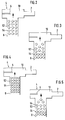
- the causes of the vacuum fluctuations in the vacuum chamber 10 are described below with reference to FIGS. 2 to 5, in which the injector 4 and the powder suction channel 8 are shown schematically.
- FIGS. 2 to 5 each show operating situations arising in successive time segments. In the first time segment shown in FIG. 2, the powder-air mixture 52 in the powder suction channel 8 is homogeneous.
- the vacuum generated by the injector 4 in the vacuum chamber 10 draws in a constant air volume flow from the powder container 14 through the powder column present in the powder suction channel 8, which is represented schematically by powder particles 54.
- the intake air volume flow is constant and the vacuum in the vacuum chamber 10 is also constant.
- the vacuum present in the vacuum chamber 10 of the injector 4 sucks off a large part of the air present in the powder suction channel 8, the vacuum in the vacuum chamber 10 being reduced, i. H. the pressure in her increases.
- the air volume flow sucked out of the powder suction channel 8 increases and the vacuum in the vacuum chamber 10 becomes smaller. In this case, the powder particles 54 remaining in the powder suction pipe 8 are compacted.
- a compensating air inlet 56 in the form of a second injector nozzle is arranged at the upstream beginning, which is axially arranged at a short distance from the upstream beginning 58 and, through a second vacuum chamber 60 formed therebetween, compensating air axially into the upstream end 58 of the powder suction channel 8 blows.
- the compensation air is fed to the second atomizer nozzle from the compressed air source 12 via a third pressure regulator 62 and a compressed air line 64 via a compensation air duct 66 which extends parallel to the powder suction duct 8.
- the powder suction duct 8 and the compensating air duct 66 are axially parallel in the immersion tube 24, in the lower end section of which the second injector nozzle 56 is also arranged is.
- the powder inlet for the powder suction channel 8 is formed by one or more powder inlet openings 68, which flow, for example radially, through the dip tube 24 through the dip tube outer surface 70 and thus the powder 16 located in the powder container 14 with the second vacuum chamber 60 of the second injector 72, which is formed by the compensating air inlet and the second vacuum chamber 60.
- the regulating device 40 regulates the supply of the conveying air, the additional air and the compensating air as a function of the measuring signal of the measuring line 38 via the pressure regulators 18, 44 and 62.
- the powder container 14 is preferably designed such that the powder 16 contained in it hovers in an air stream, the air of which flows through a perforated container bottom 74 into the interior of the container. Due to this "fluidized state" of the powder 16 in the container 14, the powder 16 has flow properties similar to air or a liquid. A much smaller amount of air per unit time is introduced into the powder stream from the compensating air inlet 56 than with the first injector nozzle 6. The compensating air from the compensating air inlet 56 can, but does not need to draw powder from the powder container 14 in the second vacuum chamber 60.
- the compensating air is supplied through this inlet 56 with a small constant amount per unit of time and thereby has a stabilizing effect on the pressure fluctuations in the powder suction channel 8 described above the fluctuations mentioned are more frequent (shorter and faster) and smaller in amplitude.
- the controller setting times of the control device 40 which tries to compensate for the fluctuations mentioned, much shorter. In trials, the standard setting times could be reduced to a third.
Landscapes
- Physics & Mathematics (AREA)
- Fluid Mechanics (AREA)
- General Physics & Mathematics (AREA)
- Engineering & Computer Science (AREA)
- Mechanical Engineering (AREA)
- Nozzles (AREA)
Applications Claiming Priority (2)
| Application Number | Priority Date | Filing Date | Title |
|---|---|---|---|
| DE4419987A DE4419987A1 (de) | 1994-06-08 | 1994-06-08 | Injektor-Fördervorrichtung zur pneumatischen Förderung von Pulver |
| DE4419987 | 1994-06-08 |
Publications (3)
| Publication Number | Publication Date |
|---|---|
| EP0686430A2 true EP0686430A2 (fr) | 1995-12-13 |
| EP0686430A3 EP0686430A3 (fr) | 1996-10-02 |
| EP0686430B1 EP0686430B1 (fr) | 1999-03-17 |
Family
ID=6520070
Family Applications (1)
| Application Number | Title | Priority Date | Filing Date |
|---|---|---|---|
| EP95105338A Expired - Lifetime EP0686430B1 (fr) | 1994-06-08 | 1995-04-08 | Injecteur pour le transport pneumatique de poudre |
Country Status (4)
| Country | Link |
|---|---|
| US (1) | US5615980A (fr) |
| EP (1) | EP0686430B1 (fr) |
| DE (2) | DE4419987A1 (fr) |
| ES (1) | ES2129693T3 (fr) |
Cited By (7)
| Publication number | Priority date | Publication date | Assignee | Title |
|---|---|---|---|---|
| EP0810501A1 (fr) * | 1996-05-29 | 1997-12-03 | Basf Aktiengesellschaft | Méthode de détermination et de réduction du degré d'oscillations dans un transport pneumatique |
| EP0962258A1 (fr) * | 1998-06-03 | 1999-12-08 | Nordson Corporation | Appareil de transfert de poudre ayant un tube de fluidisation de poudre |
| WO2000010726A1 (fr) * | 1998-08-22 | 2000-03-02 | Itw Gema Ag | Dispositif d'application de revetement en poudre |
| FR2824283A1 (fr) | 2001-05-03 | 2002-11-08 | Eisenmann France Sarl | Procede de regulation du debit de poudre transportee par un flux d'air, et dispositif pour sa mise en oeuvre |
| WO2003099450A1 (fr) | 2002-05-10 | 2003-12-04 | Eisenmann France Sarl | Procede de regulation du debit de poudre transportee par un flux d'air, et dispositif pour sa mise en oeuvre |
| WO2006024417A1 (fr) * | 2004-09-02 | 2006-03-09 | Weitmann & Konrad Gmbh & Co. Kg | Procede et dispositif pour realiser un melange poudre-air homogene |
| EP1477231B2 (fr) † | 2003-05-16 | 2021-12-01 | Dürr Systems AG | Dispositif pour la préservation des espaces creux |
Families Citing this family (24)
| Publication number | Priority date | Publication date | Assignee | Title |
|---|---|---|---|---|
| DE19531421A1 (de) * | 1995-08-26 | 1997-02-27 | Gema Volstatic Ag | Injektor-Vorrichtung zur Pulver-Sprühbeschichtung |
| EP0823286B1 (fr) * | 1996-08-07 | 2003-01-02 | Elpatronic Ag | Arrangement d'injection pour transporter des matériaux en particules |
| DE29723226U1 (de) | 1997-07-10 | 1998-06-04 | Kolb, Robert, jun., 88046 Friedrichshafen | Druckluft-Injektor zur pneumatischen Förderung eines Pulvers |
| GB9718944D0 (en) * | 1997-09-05 | 1997-11-12 | Nordson Corp | Improvements relating to powder spray coating |
| DE19748376A1 (de) | 1997-11-03 | 1999-05-06 | Itw Gema Ag | Verfahren und Vorrichtung zum Pulver-Sprühbeschichten |
| DE19748375A1 (de) | 1997-11-03 | 1999-05-06 | Itw Gema Ag | Verfahren und Vorrichtung zum Pulver-Sprühbeschichten |
| DE19836018A1 (de) * | 1998-08-10 | 2000-02-17 | Weitmann & Konrad Fa | Verfahren und Vorrichtung zum Bestäuben von bedruckten Bogen |
| US7074274B1 (en) | 1999-09-17 | 2006-07-11 | Nordson Corporation | Quick color change powder coating system |
| US6756561B2 (en) | 1999-09-30 | 2004-06-29 | National Research Council Of Canada | Laser consolidation apparatus for manufacturing precise structures |
| EP1138394A1 (fr) * | 2000-03-31 | 2001-10-04 | Nordson Corporation | Améliorations concernant un système de revêtement en poudre |
| US6730169B2 (en) | 2000-08-22 | 2004-05-04 | Nordson Corporation | Electrostatic power coating system |
| US7325750B2 (en) * | 2000-10-05 | 2008-02-05 | Nordson Corporation | Powder coating system with improved overspray collection |
| GB0100756D0 (en) | 2001-01-11 | 2001-02-21 | Powderject Res Ltd | Needleless syringe |
| DE10147858A1 (de) * | 2001-09-27 | 2003-04-30 | Itw Gema Ag | Spritzbeschichtungsvorrichtung |
| CH696062A5 (de) * | 2002-04-03 | 2006-12-15 | Kuenzler Robert Ag | Pulverinjektor. |
| DE202005001307U1 (de) * | 2005-01-26 | 2005-03-31 | Wagner Ag Altstaetten J | Fluidisiereinheit für einen Pulverförderer und Pulverförderer mit Fluidisiereinheit |
| WO2006094249A1 (fr) * | 2005-03-03 | 2006-09-08 | Durr Systems, Inc. | Système et procédé de transport de peinture en poudre |
| US7708504B2 (en) * | 2005-08-29 | 2010-05-04 | Savannah River Nuclear Solutions, Llc | Pneumatic conveyance apparatus and process |
| US20080045893A1 (en) * | 2006-02-14 | 2008-02-21 | Cardio Exodus, Llc | Imageable balloon and method of making |
| GB0708758D0 (en) | 2007-05-04 | 2007-06-13 | Powderject Res Ltd | Particle cassettes and process thereof |
| CA2686395A1 (fr) | 2007-05-09 | 2008-11-20 | Nordson Corporation | Tuyere avec rampe interne |
| DE102010039473B4 (de) * | 2010-08-18 | 2014-11-20 | Gema Switzerland Gmbh | Pulverversorgungsvorrichtung für eine Pulverbeschichtungsanlage |
| US8882400B2 (en) * | 2010-10-29 | 2014-11-11 | General Electric Company | Solids feeder discharge port |
| DE102018133713A1 (de) * | 2018-12-31 | 2020-07-02 | Gema Switzerland Gmbh | Pulverdünnstrompumpe sowie Verfahren zum Betreiben einer Pulverdünnstrompumpe |
Family Cites Families (14)
| Publication number | Priority date | Publication date | Assignee | Title |
|---|---|---|---|---|
| DE2206389C3 (de) * | 1972-02-10 | 1974-08-29 | Ernst Mueller Kg, 7057 Winnenden | Pneumatische Fördervorrichtung mit regelbarer Förderleistung |
| CH560380A5 (fr) * | 1972-12-05 | 1975-03-27 | Ciba Geigy Ag | |
| JPS57207826A (en) * | 1981-06-17 | 1982-12-20 | Hideo Nagasaka | Measuring device for flow rate of pulverulent body |
| US4544306A (en) * | 1982-02-18 | 1985-10-01 | Acf Industries, Incorporated | Automatic unloading outlet assembly |
| EP0184994B2 (fr) * | 1984-09-26 | 1992-11-19 | Siegfried Frei | Dispositif d'aspiration pour poudre |
| JPH0643911B2 (ja) * | 1985-09-17 | 1994-06-08 | アイ・ティー・エム株式会社 | 気体搬送粉体供給システム |
| JPH0780567B2 (ja) * | 1986-03-25 | 1995-08-30 | 秀雄 長坂 | 粉体自動供給装置 |
| DE3708462A1 (de) * | 1987-03-16 | 1988-09-29 | Gema Ransburg Ag | Pneumatische foerdereinrichtung |
| US4863316A (en) * | 1987-07-01 | 1989-09-05 | The Perkin-Elmer Corporation | Closed loop powder flow regulator |
| DE3721875A1 (de) * | 1987-07-02 | 1989-01-12 | Gema Ransburg Ag | Verfahren und einrichtung fuer eine pulverspruehbeschichtungsanlage |
| US5071289A (en) * | 1989-12-27 | 1991-12-10 | Alpheus Cleaning Technologies Corp. | Particulate delivery system |
| DE4012190A1 (de) * | 1990-04-14 | 1991-10-17 | Gema Ransburg Ag | Pneumatische pulvertransportvorrichtung |
| DE4114097C2 (de) * | 1991-04-30 | 1994-03-10 | Thiemt Ohg Geb | Vorrichtung zur Pulverbeschichtung |
| US5186388A (en) * | 1991-08-16 | 1993-02-16 | Electrostatic Components, Inc. | Production of composite structures using lightweight low cost matrix extender materials |
-
1994
- 1994-06-08 DE DE4419987A patent/DE4419987A1/de not_active Withdrawn
-
1995
- 1995-04-08 ES ES95105338T patent/ES2129693T3/es not_active Expired - Lifetime
- 1995-04-08 EP EP95105338A patent/EP0686430B1/fr not_active Expired - Lifetime
- 1995-04-08 DE DE59505354T patent/DE59505354D1/de not_active Expired - Fee Related
- 1995-06-07 US US08/472,839 patent/US5615980A/en not_active Expired - Lifetime
Cited By (10)
| Publication number | Priority date | Publication date | Assignee | Title |
|---|---|---|---|---|
| EP0810501A1 (fr) * | 1996-05-29 | 1997-12-03 | Basf Aktiengesellschaft | Méthode de détermination et de réduction du degré d'oscillations dans un transport pneumatique |
| EP0962258A1 (fr) * | 1998-06-03 | 1999-12-08 | Nordson Corporation | Appareil de transfert de poudre ayant un tube de fluidisation de poudre |
| US6398462B1 (en) | 1998-06-03 | 2002-06-04 | Nordson Corporation | Powder transfer apparatus having powder fluidizing tube |
| WO2000010726A1 (fr) * | 1998-08-22 | 2000-03-02 | Itw Gema Ag | Dispositif d'application de revetement en poudre |
| US6598803B1 (en) | 1998-08-22 | 2003-07-29 | Itw Gema Ag | Powder spray coating device |
| FR2824283A1 (fr) | 2001-05-03 | 2002-11-08 | Eisenmann France Sarl | Procede de regulation du debit de poudre transportee par un flux d'air, et dispositif pour sa mise en oeuvre |
| WO2003099450A1 (fr) | 2002-05-10 | 2003-12-04 | Eisenmann France Sarl | Procede de regulation du debit de poudre transportee par un flux d'air, et dispositif pour sa mise en oeuvre |
| EP1477231B2 (fr) † | 2003-05-16 | 2021-12-01 | Dürr Systems AG | Dispositif pour la préservation des espaces creux |
| WO2006024417A1 (fr) * | 2004-09-02 | 2006-03-09 | Weitmann & Konrad Gmbh & Co. Kg | Procede et dispositif pour realiser un melange poudre-air homogene |
| US7607451B2 (en) | 2004-09-02 | 2009-10-27 | Weitmann & Konrad Gmbh & Co. Kg | Device and method for the production of a powder-air mixture |
Also Published As
| Publication number | Publication date |
|---|---|
| EP0686430B1 (fr) | 1999-03-17 |
| DE59505354D1 (de) | 1999-04-22 |
| DE4419987A1 (de) | 1996-02-29 |
| US5615980A (en) | 1997-04-01 |
| ES2129693T3 (es) | 1999-06-16 |
| EP0686430A3 (fr) | 1996-10-02 |
Similar Documents
| Publication | Publication Date | Title |
|---|---|---|
| EP0686430B1 (fr) | Injecteur pour le transport pneumatique de poudre | |
| EP0412289B1 (fr) | Dispositif de pulvérisation électrostatique | |
| EP0823286B1 (fr) | Arrangement d'injection pour transporter des matériaux en particules | |
| EP1104334B1 (fr) | Dispositif d'application de revetement en poudre | |
| EP1550511B1 (fr) | Dispositif et procédé de production d'un aérosol | |
| DE3222727A1 (de) | Vorrichtung zur messung der stroemungsrate von pulverfoermigen substanzen | |
| EP3906120B1 (fr) | Pompe à flux clair de refoulement de poudre | |
| WO2017186355A1 (fr) | Dispositif d'alimentation en poudre, pour alimenter en poudre de revêtement un applicateur de poudre, installation de revêtement par poudre et procédé pour faire fonctionner le dispositif d'alimentation en poudre | |
| DE4201665A1 (de) | Pulver-injektor | |
| DE102007041551A1 (de) | Pulversprühbeschichtungsvorrichtung und Beschichtungspulver-Fördervorrichtung dafür | |
| EP3585522A1 (fr) | Pompe à poudre en phase dense | |
| EP0490174A1 (fr) | Procédé pour le transport de matière en vrac et dispositif pour la mise en oeuvre du procédé | |
| DE102019101930A1 (de) | Pulverabgabevorrichtung mit einer Pulverdünnstrompumpe | |
| DE10111891A1 (de) | Pulversprüheinrichtung für Beschichtungspulver | |
| DE102007048520A1 (de) | Sprühbeschichtungspulver-Fördervorrichtung und Pulversprühbeschichtungsvorrichtung | |
| DE19943504C2 (de) | Verfahren und Vorrichtung zur pneumatischen Förderung von Schüttgut | |
| DE10261276B4 (de) | Vorlagebehälter für pulverförmige Medien | |
| EP1337451B1 (fr) | Procede pour le transport pneumatique de produits en vrac | |
| EP1433538B1 (fr) | Récipient pour produits pulvérulents | |
| DE10008389A1 (de) | Verfahren und Leitungssystem zur Beeinflussung des Tropfenspektrums von fluiden Stoffen bei deren Zerstäubung | |
| DE10008158A1 (de) | Verfahren und Leitungssystem zur Zuführung von fluiden Stoffen zu einer oder mehreren Düsen | |
| WO2023030863A1 (fr) | Appareil de mesure pour mesure de débit massique de poudre de revêtement pouvant être généré par un gaz comprimé dans une conduite de poudre, et appareil de transport de poudre de revêtement | |
| EP0897754B1 (fr) | Installation de revêtement par poudre avec un réservoir | |
| WO2008006421A1 (fr) | Dispositif d'alimentation en matières fluidifiables |
Legal Events
| Date | Code | Title | Description |
|---|---|---|---|
| PUAI | Public reference made under article 153(3) epc to a published international application that has entered the european phase |
Free format text: ORIGINAL CODE: 0009012 |
|
| 17P | Request for examination filed |
Effective date: 19950408 |
|
| AK | Designated contracting states |
Kind code of ref document: A2 Designated state(s): CH DE ES FR IT LI SE |
|
| PUAL | Search report despatched |
Free format text: ORIGINAL CODE: 0009013 |
|
| AK | Designated contracting states |
Kind code of ref document: A3 Designated state(s): CH DE ES FR IT LI SE |
|
| 17Q | First examination report despatched |
Effective date: 19980415 |
|
| GRAG | Despatch of communication of intention to grant |
Free format text: ORIGINAL CODE: EPIDOS AGRA |
|
| GRAG | Despatch of communication of intention to grant |
Free format text: ORIGINAL CODE: EPIDOS AGRA |
|
| GRAG | Despatch of communication of intention to grant |
Free format text: ORIGINAL CODE: EPIDOS AGRA |
|
| GRAH | Despatch of communication of intention to grant a patent |
Free format text: ORIGINAL CODE: EPIDOS IGRA |
|
| GRAH | Despatch of communication of intention to grant a patent |
Free format text: ORIGINAL CODE: EPIDOS IGRA |
|
| GRAA | (expected) grant |
Free format text: ORIGINAL CODE: 0009210 |
|
| RAP3 | Party data changed (applicant data changed or rights of an application transferred) |
Owner name: ITW GEMA AG |
|
| AK | Designated contracting states |
Kind code of ref document: B1 Designated state(s): CH DE ES FR IT LI SE |
|
| REG | Reference to a national code |
Ref country code: CH Ref legal event code: NV Representative=s name: E. BLUM & CO. PATENTANWAELTE Ref country code: CH Ref legal event code: EP |
|
| REF | Corresponds to: |
Ref document number: 59505354 Country of ref document: DE Date of ref document: 19990422 |
|
| ET | Fr: translation filed | ||
| ITF | It: translation for a ep patent filed | ||
| REG | Reference to a national code |
Ref country code: ES Ref legal event code: FG2A Ref document number: 2129693 Country of ref document: ES Kind code of ref document: T3 |
|
| PLBE | No opposition filed within time limit |
Free format text: ORIGINAL CODE: 0009261 |
|
| STAA | Information on the status of an ep patent application or granted ep patent |
Free format text: STATUS: NO OPPOSITION FILED WITHIN TIME LIMIT |
|
| 26N | No opposition filed | ||
| REG | Reference to a national code |
Ref country code: CH Ref legal event code: PFA Owner name: ITW GEMA AG Free format text: ITW GEMA AG#MOEVENSTRASSE 17#9015 ST. GALLEN (CH) -TRANSFER TO- ITW GEMA AG#MOEVENSTRASSE 17#9015 ST. GALLEN (CH) |
|
| PGFP | Annual fee paid to national office [announced via postgrant information from national office to epo] |
Ref country code: ES Payment date: 20080428 Year of fee payment: 14 Ref country code: DE Payment date: 20080602 Year of fee payment: 14 Ref country code: CH Payment date: 20080430 Year of fee payment: 14 |
|
| PGFP | Annual fee paid to national office [announced via postgrant information from national office to epo] |
Ref country code: IT Payment date: 20080428 Year of fee payment: 14 |
|
| PGFP | Annual fee paid to national office [announced via postgrant information from national office to epo] |
Ref country code: SE Payment date: 20080429 Year of fee payment: 14 |
|
| PGFP | Annual fee paid to national office [announced via postgrant information from national office to epo] |
Ref country code: FR Payment date: 20080417 Year of fee payment: 14 |
|
| REG | Reference to a national code |
Ref country code: CH Ref legal event code: PL |
|
| EUG | Se: european patent has lapsed | ||
| REG | Reference to a national code |
Ref country code: FR Ref legal event code: ST Effective date: 20091231 |
|
| PG25 | Lapsed in a contracting state [announced via postgrant information from national office to epo] |
Ref country code: LI Free format text: LAPSE BECAUSE OF NON-PAYMENT OF DUE FEES Effective date: 20090430 Ref country code: DE Free format text: LAPSE BECAUSE OF NON-PAYMENT OF DUE FEES Effective date: 20091103 Ref country code: CH Free format text: LAPSE BECAUSE OF NON-PAYMENT OF DUE FEES Effective date: 20090430 |
|
| PG25 | Lapsed in a contracting state [announced via postgrant information from national office to epo] |
Ref country code: FR Free format text: LAPSE BECAUSE OF NON-PAYMENT OF DUE FEES Effective date: 20091222 |
|
| REG | Reference to a national code |
Ref country code: ES Ref legal event code: FD2A Effective date: 20090411 |
|
| PG25 | Lapsed in a contracting state [announced via postgrant information from national office to epo] |
Ref country code: ES Free format text: LAPSE BECAUSE OF NON-PAYMENT OF DUE FEES Effective date: 20090411 |
|
| PG25 | Lapsed in a contracting state [announced via postgrant information from national office to epo] |
Ref country code: IT Free format text: LAPSE BECAUSE OF NON-PAYMENT OF DUE FEES Effective date: 20090408 |
|
| PG25 | Lapsed in a contracting state [announced via postgrant information from national office to epo] |
Ref country code: SE Free format text: LAPSE BECAUSE OF NON-PAYMENT OF DUE FEES Effective date: 20090409 |