EP0686445A1 - Procédé de régulation de la déformation des faces latérales d'une lingotière, et lingotière pour la coulée continue - Google Patents
Procédé de régulation de la déformation des faces latérales d'une lingotière, et lingotière pour la coulée continue Download PDFInfo
- Publication number
- EP0686445A1 EP0686445A1 EP95107644A EP95107644A EP0686445A1 EP 0686445 A1 EP0686445 A1 EP 0686445A1 EP 95107644 A EP95107644 A EP 95107644A EP 95107644 A EP95107644 A EP 95107644A EP 0686445 A1 EP0686445 A1 EP 0686445A1
- Authority
- EP
- European Patent Office
- Prior art keywords
- crystalliser
- sidewall
- cooling fluid
- zone
- inclusive
- Prior art date
- Legal status (The legal status is an assumption and is not a legal conclusion. Google has not performed a legal analysis and makes no representation as to the accuracy of the status listed.)
- Granted
Links
- 238000000034 method Methods 0.000 title claims abstract description 33
- 238000009749 continuous casting Methods 0.000 title claims abstract description 11
- 239000012809 cooling fluid Substances 0.000 claims abstract description 73
- 238000001816 cooling Methods 0.000 claims abstract description 35
- 230000005499 meniscus Effects 0.000 claims abstract description 15
- 238000000926 separation method Methods 0.000 claims abstract description 11
- 229910001338 liquidmetal Inorganic materials 0.000 claims abstract description 7
- 230000002596 correlated effect Effects 0.000 claims abstract description 4
- 238000006073 displacement reaction Methods 0.000 claims abstract description 4
- 239000012530 fluid Substances 0.000 claims description 15
- 239000000463 material Substances 0.000 claims description 11
- 239000002184 metal Substances 0.000 claims description 10
- 229910052751 metal Inorganic materials 0.000 claims description 10
- XLYOFNOQVPJJNP-UHFFFAOYSA-N water Substances O XLYOFNOQVPJJNP-UHFFFAOYSA-N 0.000 claims description 10
- 238000005266 casting Methods 0.000 claims description 9
- 230000009467 reduction Effects 0.000 claims description 8
- 238000009529 body temperature measurement Methods 0.000 claims description 7
- 239000007788 liquid Substances 0.000 claims description 6
- LYCAIKOWRPUZTN-UHFFFAOYSA-N Ethylene glycol Chemical compound OCCO LYCAIKOWRPUZTN-UHFFFAOYSA-N 0.000 claims description 4
- 229910045601 alloy Inorganic materials 0.000 claims description 3
- 239000000956 alloy Substances 0.000 claims description 3
- 150000001247 metal acetylides Chemical class 0.000 claims description 3
- 150000002739 metals Chemical class 0.000 claims description 3
- 239000007921 spray Substances 0.000 claims description 3
- 239000000126 substance Substances 0.000 claims description 3
- WGCNASOHLSPBMP-UHFFFAOYSA-N hydroxyacetaldehyde Natural products OCC=O WGCNASOHLSPBMP-UHFFFAOYSA-N 0.000 claims description 2
- 238000005507 spraying Methods 0.000 claims description 2
- 230000008021 deposition Effects 0.000 claims 2
- 239000000654 additive Substances 0.000 claims 1
- 230000000875 corresponding effect Effects 0.000 claims 1
- 238000012986 modification Methods 0.000 claims 1
- 230000004048 modification Effects 0.000 claims 1
- 230000004907 flux Effects 0.000 description 9
- 238000000605 extraction Methods 0.000 description 5
- 230000015572 biosynthetic process Effects 0.000 description 3
- 230000000694 effects Effects 0.000 description 3
- 238000004519 manufacturing process Methods 0.000 description 3
- 239000000203 mixture Substances 0.000 description 3
- 230000010355 oscillation Effects 0.000 description 3
- RYGMFSIKBFXOCR-UHFFFAOYSA-N Copper Chemical compound [Cu] RYGMFSIKBFXOCR-UHFFFAOYSA-N 0.000 description 2
- 230000006978 adaptation Effects 0.000 description 2
- 230000008859 change Effects 0.000 description 2
- 229910052802 copper Inorganic materials 0.000 description 2
- 239000010949 copper Substances 0.000 description 2
- 238000009472 formulation Methods 0.000 description 2
- 239000007789 gas Substances 0.000 description 2
- 238000010438 heat treatment Methods 0.000 description 2
- 238000005259 measurement Methods 0.000 description 2
- 230000008569 process Effects 0.000 description 2
- 238000011084 recovery Methods 0.000 description 2
- 229910000881 Cu alloy Inorganic materials 0.000 description 1
- 229910000831 Steel Inorganic materials 0.000 description 1
- 238000005299 abrasion Methods 0.000 description 1
- 238000005219 brazing Methods 0.000 description 1
- 230000001419 dependent effect Effects 0.000 description 1
- 230000006872 improvement Effects 0.000 description 1
- 239000010687 lubricating oil Substances 0.000 description 1
- 239000000843 powder Substances 0.000 description 1
- 230000000750 progressive effect Effects 0.000 description 1
- 230000001105 regulatory effect Effects 0.000 description 1
- 239000007787 solid Substances 0.000 description 1
- 238000007711 solidification Methods 0.000 description 1
- 230000008023 solidification Effects 0.000 description 1
- 239000010959 steel Substances 0.000 description 1
Images


Classifications
-
- B—PERFORMING OPERATIONS; TRANSPORTING
- B22—CASTING; POWDER METALLURGY
- B22D—CASTING OF METALS; CASTING OF OTHER SUBSTANCES BY THE SAME PROCESSES OR DEVICES
- B22D11/00—Continuous casting of metals, i.e. casting in indefinite lengths
- B22D11/12—Accessories for subsequent treating or working cast stock in situ
- B22D11/124—Accessories for subsequent treating or working cast stock in situ for cooling
-
- B—PERFORMING OPERATIONS; TRANSPORTING
- B22—CASTING; POWDER METALLURGY
- B22D—CASTING OF METALS; CASTING OF OTHER SUBSTANCES BY THE SAME PROCESSES OR DEVICES
- B22D11/00—Continuous casting of metals, i.e. casting in indefinite lengths
- B22D11/04—Continuous casting of metals, i.e. casting in indefinite lengths into open-ended moulds
- B22D11/055—Cooling the moulds
-
- B—PERFORMING OPERATIONS; TRANSPORTING
- B22—CASTING; POWDER METALLURGY
- B22D—CASTING OF METALS; CASTING OF OTHER SUBSTANCES BY THE SAME PROCESSES OR DEVICES
- B22D11/00—Continuous casting of metals, i.e. casting in indefinite lengths
- B22D11/16—Controlling or regulating processes or operations
-
- B—PERFORMING OPERATIONS; TRANSPORTING
- B22—CASTING; POWDER METALLURGY
- B22D—CASTING OF METALS; CASTING OF OTHER SUBSTANCES BY THE SAME PROCESSES OR DEVICES
- B22D11/00—Continuous casting of metals, i.e. casting in indefinite lengths
- B22D11/16—Controlling or regulating processes or operations
- B22D11/22—Controlling or regulating processes or operations for cooling cast stock or mould
-
- B—PERFORMING OPERATIONS; TRANSPORTING
- B01—PHYSICAL OR CHEMICAL PROCESSES OR APPARATUS IN GENERAL
- B01D—SEPARATION
- B01D9/00—Crystallisation
- B01D9/0004—Crystallisation cooling by heat exchange
Definitions
- This invention concerns a method to control the deformations of the sidewalls of a crystalliser, and a continuous-casting crystalliser, as set forth in the respective main claims.
- the invention is employed in association with a mould used in a continuous casting plant for the production of billets, blooms or slabs of any desired type and section.
- the field of continuous casting still entails a plurality of problems which have not yet been overcome and which are linked to the high temperatures to which the sidewalls of the crystalliser are subjected.
- the uneven temperature along the sidewalls of the crystalliser causes an uneven deformation of those sidewalls together with their outward displacement in relation to their initial position in the cold state, this deformation being due to the thermal expansion of the material, with resulting problems linked to the surface faults caused by this uneven deformation on the billets or blooms being formed.
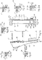
- Fig.1b indicates with the reference line "O" the position in the cold state of the sidewall 212 of the crystalliser, which in this case is shown as being straight but which could also take on one of the different known forms with which the sidewalls of the crystalliser are embodied.
- the strongly negative taper shown with the line "28" in the upper zone 37 causes the solidifying billet/bloom/slab 24 to penetrate deeply within the deformed sidewall 112 of the crystalliser with resulting great difficulties of extraction and descent of the cast product.
- an air space of a value "g1" is caused in the lower zone 38 of the crystalliser between the sidewall 112 of the crystalliser and the skin of the product owing both to the shrinkage of the solidifying skin and to the outward deformation of the sidewall 112 due to the thermal field.
- the progressive separation of the skin from the sidewall 112 of the crystalliser takes on great values and involves problems of the uniformity of the cooling, with a resulting very great reduction of heat exchange and therefore of formation of the skin.
- the heat exchange in the rigid crystallisers of the state of the art has acceptable values only along the first segment 137 of the crystalliser extending along about one quarter of the length of the same, normally about 200 mm. below the meniscus, where the skin of the billet/bloom/slab is substantially in contact with the sidewall of the crystalliser.
- the heat exchange is greatly reduced to a value of heat flux of about 1.5 to 2 MW/m2.
- crystalliser models having a variable section have been disclosed in which the sidewalls converge in the downward direction; to be more exact, the shape of the development of the sidewalls of the crystalliser along the casting direction has been proposed to be a function of the coefficient of shrinkage of the material.
- the skin of the billet or bloom at the corners is less thick than along the sidewalls of the billet or bloom, and gradients of temperature between the corners and the sides of the billet or bloom are created.
- the inner surface of those sidewalls is generally lined with Ni/Cr , which however possesses little slipperiness.
- the purpose of this invention is to provide a method to control the deformations of the single sidewalls of a crystalliser for the continuous casting of billets/blooms/slabs, so that this deformation is almost nil, together with cancellation of the negative taper of the first segment of the crystalliser or even with the taper being directed towards the inside of the crystalliser with a view to improving the working of the crystalliser and to achieving greater extraction speeds.
- a further purpose is to provide a crystalliser in which, on the one hand, the separation of the skin of the solidifying billet/ bloom/slab from the sidewall of the crystalliser is reduced and, on the other hand, the thermal deformation of the single sidewalls of the crystalliser is compensated so that the sidewalls follow the natural shrinkage of the solidifying billet/ bloom/slab.
- the crystalliser according to the invention has sidewalls with an average thickness of a reduced value, between 4 and 15 mm. but advantageously between 4 and 10 mm., in proportion to their width, so that they have a substantially resilient behaviour according to the pressure of the cooling fluid acting on the outside of the sidewalls.
- This pressure has a value strictly correlated with that thickness so as to ensure the resilient behaviour.
- the single sidewalls of the crystalliser according to the invention adapt themselves to the respective sides of the billet/bloom/slab being formed while that billet/bloom/slab solidifies during its passage through the crystalliser.
- this adaptation of the sidewalls of the crystalliser is caused by the pressure of the cooling fluid, so that, by acting longitudinally on the pressure or on the reduction of pressure within a channel for circulation of the cooling fluid, the deformation induced in the sidewall is varied, thus also making possible the adaptation of the crystalliser to a plurality of types of cast metal and to various fields of casting speeds.
- the sidewalls of the crystalliser have specific longitudinal zones associated with a specific pressure of the cooling fluid, the pressure being variable between one longitudinal zone and another according to a desired range of pressures.
- a second formulation of the invention arranges that at least one longitudinal sidewall of the crystalliser is associated with at least one specific range of pressures of the cooling fluid.
- cooling fluid is generally meant water for industrial use, at any rate water which is normally used to cool the crystalliser, and such water will be employed hereinafter as a reference element.
- the invention arranges to employ as a cooling fluid water to which has been added substances which enable that water to be used even at temperatures lower than "0" and down to -25°C/-30°C upon entry into the mould.
- a variant of the invention arranges for the use, as a cooling fluid, of other liquid substances such as glycol, for instance, at a temperature between -10°C/-15°C and -70°C/-80°C upon entry into the mould.
- a further variant of the invention covers the use, as a cooling fluid, of liquefied gases, whether pure or combined with other gases or liquids, at a temperature between -3°C and -270°C upon entry into the mould.
- cooling fluid water, also called normal water, as normally used to cool continuous casting moulds in an industrial process.
- the crystalliser is embodied in such a way that its dimensions in its transverse direction already take partial account of thermal expansion due to its heating; in such a case the vertical median line in the cold state may be straight or may already have a positive taper substantially in the vicinity of the meniscus.
- the crystalliser is advantageously dimensioned in such a way that its cross-section, when it is in the state of normal expansion owing to the inclusion of liquid metal within it, corresponds substantially to the section of the billet/bloom/slab which is to be produced at its outlet.
- the crystalliser is dimensioned in such a way that its longitudinal section takes into account a typical expansion for a given range of steels which are to be cast with that crystalliser.
- the invention provides for the use of pressures much higher than those normally used; in any event the invention arranges that the pressure of the cooling fluid is correlated with the deformation desired at a given longitudinal zone of the sidewall of the crystalliser in relation to the thickness of that sidewall, to the characteristics of the material forming that sidewall (normally copper or copper alloy), to the characteristics of the cast material and to the extraction speed.
- the pressure at which the cooling fluid is fed is therefore at least a function of the inward deformation to be imparted to the sidewall of the crystalliser, or at least to a zone of that sidewall in relation to the thickness of the relative sidewall at that zone.
- the invention arranges that the pressure of the cooling fluid is such as will deform the sidewalls of the crystalliser inwards so as at least to recover the deformation induced by the thermal field along the crystalliser in order to keep the sidewall substantially straight along the nominal line in the cold state, or even displaced positively in relation to that nominal line.
- the scope of the invention includes also the correlation of the pressure of the cooling fluid with the value of the thermal flux to be removed from the molten metal through the sidewall of the crystalliser.
- the pressure of the cooling fluid acting against the sidewalls of the crystalliser recovers the deformation induced by the heat in those sidewalls of the crystalliser and makes them linear or substantially linear or even induces in them a positive displacement, namely towards the inside of the casting chamber.
- the pressure of the cooling fluid eliminates the negative taper caused in the case of rigid crystallisers (Figs.1a and 1b), thus bringing about an improvement of the surface of the solidifying skin and a minimisation of the depth of the oscillation marks, namely those notches created in the skin owing to the oscillation of the mould during the descent of the cast product.
- the pressure of the cooling fluid can alter as desired the local or complete taper of the sidewalls.
- the pressure of the cooling fluid has the result of minimising or even eliminating the air space created between the sidewalls of the crystalliser and the solidified skin of the billet/bloom/slab.
- the pressure of the cooling fluid can be varied by maintaining a constant ⁇ P along the whole fluid circulation channel of a determined zone, so as to induce a substantially constant deformation or recovery of deformation along that whole zone.
- the ⁇ P between the inlet and outlet can be made variable through one and the same fluid circulation channel so as to induce variable deformations or recovery of deformations suitable for the obtaining of a desired result along the height of the crystalliser.
- the crystalliser is associated, in the longitudinal direction, with at least two cooling chambers with the relative fluid circulation channels so as to obtain at least two longitudinally consecutive and independently manageable zones, so that in those zones there may be differentiated and independent ranges of pressure of the cooling fluid.
- differentiated and independent cooling zones can also be obtained.
- the cooling conditions and pressure are governed by a data processor which receives the necessary information from measurement means, which cooperate with the sidewalls of the crystalliser and/or with the surface of the billet/bloom/ slab emerging from the crystalliser.
- the measurement means may be means to detect the temperature of the sidewalls of the crystalliser or else, or also, means to detect the surface temperature of the billet/bloom/slab in the vicinity of the position of the exit of the same from the crystalliser, or else, or also, means to detect the force of friction between the inner side of the sidewalls of the crystalliser and the skin of the forming billet/bloom/slab.
- the temperature measurement means are associated at least with the lower part of the crystalliser where the separation of the skin from the sidewalls of the crystalliser takes place.
- the temperature measurement means are also associated with the surface of the billet/bloom/slab as the latter leaves the crystalliser.
- the pressures according to the invention vary from 3 to 15 bar.
- the pressure according to the invention vary from 5 to 20 bar.
- the invention arranges to increase in feedback the pressure of the cooling fluid so as to bring the value of the air space back to the desired value.
- the wider sidewalls of the rectangle of the crystalliser are governed by independent pressures different from the pressures acting on the narrower sidewalls.
- the sidewalls are subjected to the same range of pressures but with an effect variable in relation to the different width, and possibly different thickness, of the sidewall.
- the invention arranges that each side of the crystalliser is subjected to its own independent range of pressures of the cooling fluid.
- the cooling fluid can flow in the same direction as, or in the opposite direction to, the direction of feed of the billet/bloom within the casting chamber.
- the fluid circulation channels do not affect the corner zones of the crystalliser, the purpose being to prevent causing an excessive cooling of the corners of the billet/bloom/slab being formed.
- This situation ensures a uniform growth of the solidified layer and eliminates the tendency of the outgoing billet/bloom to take on a rhomboidal section.
- these corners zone are cooled in a different manner from the rest of the sidewalls of the crystalliser.
- the crystalliser according to the invention includes stiffening elements suitable at least to control the deformations of the crystalliser caused by the thermal expansion as a result of the heating of the crystalliser.
- stiffening elements are embodied directly in the crystalliser itself or are auxiliary external elements which are secured to, or are caused to cooperate with, the corners of the crystalliser.
- the crystalliser according to the invention advantageously has its inner surface lined with lining materials possessing good thermal conductivity, good wear resistance and great slipperiness (low coefficient of friction), such as the carbides and/or other alloys of hard metals.
- the lining materials are advantageously applied by means of the plasma spray technique, which ensures excellent adhesion of the lining materials even to the copper sidewalls.
- At least part of one surface of the fluid circulation channel includes flow disturbing means, which break up the fluid streams of the outermost layer of the fluid and cause the cooling fluid to run in a turbulent manner with a resulting increase of the heat exchange.
- the disturbing means can be embodied by means of rough areas, hollows, sequences of enlargements and narrowings, etc.
- the outer surface of the sidewalls of the crystalliser may include ribs or other shapes.
- the intermediate walls defining the fluid circulation chambers can be moved in relation to the sidewalls of the crystalliser and cooperate with adjustment means for their approach towards, or distancing from, those sidewalls.
- This adjustment can be perpendicular to the sidewalls or can make possible the obtaining of desired angles between the sidewalls of the crystalliser and the intermediate walls.
- the reference number 10 in the attached figures denotes generally a mould according to the invention, with which a nozzle 25 to discharge molten metal is caused to cooperate.
- the mould 10 can have a square, rectangular or polygonal cross-section or any desired cross-section.
- the mould 10 according to the invention comprises a crystalliser 11 the sidewalls 12 of which have a thickness between 4 and 15 mm., but advantageously between 4 and 10 mm.
- the sidewalls 12 of the crystalliser 11 have at least their inner surface lined with a material having a good thermal conductivity, a good resistance to wear and great slipperiness (a low coefficient of friction), such as the carbides for instance or other alloys of hard metals.
- lining materials are advantageously applied by the plasma spray technique or by hypersonic spraying.
- the mould 10 comprises containing walls 13 positioned outside the crystalliser 11 and defining therewith cooling chambers 14 in which a cooling fluid is caused to run.
- the cooling chamber 14 is one single longitudinal chamber and takes up the whole longitudinal extent of the sidewall 12 of the crystalliser 11.
- two or more cooling chambers 14 are positioned longitudinally in sequence and in them the cooling fluid under pressure circulates independently.
- the cooling fluid can circulate in the opposite direction to, or in the same direction as, the direction of feed of the billet/bloom/slab 24 being formed.
- the cooling chambers 14 includes a feeder conduit 22a-122a equipped with an adjustment valve 23a-123a and a discharge conduit 22b-122b also equipped with an adjustment valve 23b-123b.
- These adjustment valves 23a-23b-123a-123b have the purpose of adjusting in a desired manner the feed pressure and/or the reduction of pressure of the cooling fluid within the specific cooling chambers 14-114-214.
- the cooling chambers 14 in the mould 10 according to the invention contain on each side of the crystalliser 11 their own specific intermediate walls 20, which can be moved transversely according to the arrows 17 of Figs.3a-3b and 4a-4b by means of relative motors 32.
- a fluid circulation channel 21 is provided between the intermediate wall 20 and the sidewall 12 of the crystalliser 11 and has a variable cross-section of its passage if the intermediate wall 20 is movable.
- the intermediate wall 20 is embodied with two parts, namely an upper part 120 and a lower part 220 with a line of connection 39 but can also be embodied with a plurality of parts.
- connection between the upper 120 and lower 220 parts is obtained at 39 by means of a hinge, a plurality of hinges or in another manner, so that it is possible to change independently the transverse width of the circulation channel 21 by modifying its geometry.
- the wider sidewalls have pressure factors different from the pressure factors of the narrower sidewalls.
- each sidewall has its own independent range of pressures.
- each sidewall is divided into longitudinal zones defined by a specific range of pressures of the cooling fluid.
- Figs.1a-1b and 4a-4b show the behaviour of crystallisers of the state of the art (Figs.1a-1b) and crystallisers according to the invention (Figs.4a-4b).
- the crystalliser 11 in the vicinity of the meniscus 27 and therebelow, namely in the upper zone 37, is heated by the liquid metal running within the casting chamber 31 and is deformed outwards in a resilient manner (sidewall 112), and the pressure of the cooling fluid acting in the specific circulation channels 21-121 of that zone 37 acts in such a manner as to compensate that deformation and reduces it, thus cancelling the negative taper induced in the sidewalls or even imparting to the sidewalls a partial positive taper towards the inside of the casting chamber 31 (sidewall 12).
- the pressure of the cooling fluid in the relative specific circulation channel 21-221 enables the interspace 36 between the sidewall 12 of the crystalliser 11 and the skin of the solidifying billet/bloom/ slab 24 to be reduced until it has been cancelled.
- Figs.1a and 1b show with the line 28 that at the meniscus 27 the sidewall 12 of the crystalliser 11 bulges outwards and thereafter takes up lower down a positive taper; in the meantime the skin being formed of the billet/bloom/slab 24 has shrunk and creates, together with the outward deformation induced by the thermal field, an air interspace 36 of a value "g1" , which reduces severely the removed heat flux.
- the pressure of the cooling fluid eliminates the negative taper of the sidewall 12 of the crystalliser 11 in the zone below the meniscus 27 and, by displacing the sidewall 12 inwards, recovers and substantially cancels the air interspace 36.
- At least its wider sidewalls include circulation chambers 14 and circulation channels 21 which are independent and have independent pressures of the cooling fluid.
- the cooling chamber 14 in the example shown in Figs.3b and 4b is divided by separator walls 34 into two cooling chambers 114-214, each with its own independent circulation of cooling fluid 22a-22b-23a-23b-122a-122b-123a-123b.
- the independent circulation can be extended so as to affect also single longitudinal zones of sidewall 12 of the crystalliser 11.
- the circulation channels 21 do not cooperate directly with the corners 15 of the crystalliser 11, which are not cooled by the cooling fluid running within the circulation channels 21.
- a segment 35 of an increased thickness is included at the corners 15 of the crystalliser 11 so as to reduce the heat exchange with the cooling fluid.
- the segment 35 of an increased thickness can be embodied by means of stiffening elements 16 obtained wholly (16a - Fig.2c) or partly (116a - Figs.2b and 2d) directly in the sidewall 12 of the crystalliser 11 or may consist of independent stiffening elements 16b (Figs.2a-2e-2f).
- the independent stiffening elements 16b can be associated with or rigidly connected, by brazing for instance, to the corners 15 of the crystalliser 11 according to the invention.
- a stiffening element 16a-116a provided in the sidewall 12 of the crystalliser 11 can be conformed as a solid polygon or have a T-shape or another form.
- stiffening elements 16b are independent, they can be conformed as a "T” , or an "L” or an “ ⁇ ” or can have other forms.
- the stiffening element which in Fig.2d is provided partly 116a in the sidewall 12 of the crystalliser 11, whereas in Fig.2f it is an independent element 16b, is T-shaped and is inserted in a space 29 defined in the segment 35 of an increased thickness.
- Cooling fluid may or may not run through the space 29.
- the stiffening element 16 which may also consist of a plurality of pieces, performs the double task of stiffening and of reducing the heat exchange at the corners 15 of the crystalliser 11.
- the segment 35 of an increased thickness has a stiffening element which is not in direct contact with the corners 15b of the crystalliser 11 but is separated therefrom by a given distance of about 0.3 to 0.6 mm.
- the embodiment relating to the corner 15b and the variant thereof relating to the corner 15c define a geometry suitable to increase the turbulence of the circulating cooling fluid and, amongst other things, to facilitate the alignment of the crystalliser 11.
- the circulation channel 21 cooperates at its lateral ends with lateral inclined walls 30 having an inclination which can be varied as required so as to modulate and graduate the heat exchange near the corners 15 of the crystalliser 11 (Figs.2f-5).
- the crystalliser 11 can be moved vertically and be rested on load cells 26, which record the force of friction of the billet/bloom /slab 24 against the sidewalls 12 of the crystalliser 11.
- the crystalliser 11 is associated, at various heights and advantageously along its whole length, with temperature measurement means 19-119, which measure respectively the temperature of the various zones on the sidewalls 12 of the crystalliser 11 and at the exit of the billet/bloom/slab 24 and on the billet/bloom/slab 24 leaving that exit.
- the load cells 26 and the temperature measurement means 19-119 send their data to a data processor 18 which governs the adjustment valves 23a-23b-123a-123b and adjusts as required the pressure in the various cooling chambers 14-114-214 and in the respective circulation channels 21-121-221 and even in relation to each single vertical portion of the sidewalls 12.
- the data processor 18 can also govern the motors 32 adjusting the transverse width, or span, of the circulation channels 21-121-221 and can regulate and, at any rate, control electromagnetic stirrers 33-133 so as to cause a circulation of their magnetic flow in the same direction or in opposite directions.
- the surfaces which define the circulation channels 21 can advantageously include disturbing elements, which break the fluid streams of the outermost layer of the fluid and cause the cooling fluid to run with a turbulent motion within the circulation channels 21 with a resulting increase of heat exchange.
- These disturbing elements may be embodied on the outer surface of the sidewalls 12 of the crystalliser 11 and on the inner surface of the intermediate wall 20.
- the outer surface of the sidewalls 12 of the crystalliser 11 may include grooves, rough areas, jutting portions or other means suitable to increase the surface of heat exchange, these grooves, rough areas, jutting portions or other means advantageously, but not only, extending vertically.
Landscapes
- Engineering & Computer Science (AREA)
- Mechanical Engineering (AREA)
- Continuous Casting (AREA)
- Heat Treatments In General, Especially Conveying And Cooling (AREA)
- Treatment Of Steel In Its Molten State (AREA)
- Organic Low-Molecular-Weight Compounds And Preparation Thereof (AREA)
- Crystals, And After-Treatments Of Crystals (AREA)
Applications Claiming Priority (6)
| Application Number | Priority Date | Filing Date | Title |
|---|---|---|---|
| IT94UD000096 IT1267249B1 (it) | 1994-06-06 | 1994-06-06 | Cristallizzatore a pareti sottili |
| ITUD940096 | 1994-06-06 | ||
| IT95UD000015A IT1280123B1 (it) | 1995-02-06 | 1995-02-06 | Procedimento di controllo delle deformazioni delle pareti di un cristallizzatore e cristallizzatore a pareti sottili per colata |
| ITUD950013 | 1995-02-06 | ||
| ITUD950015 | 1995-02-06 | ||
| ITUD950013 IT1280121B1 (it) | 1995-02-06 | 1995-02-06 | Procedimento di controllo delle deformazioni delle pareti di un cristallizzatore e cristallizzatore a pareti sottili per colata |
Publications (2)
| Publication Number | Publication Date |
|---|---|
| EP0686445A1 true EP0686445A1 (fr) | 1995-12-13 |
| EP0686445B1 EP0686445B1 (fr) | 2000-08-16 |
Family
ID=27274209
Family Applications (1)
| Application Number | Title | Priority Date | Filing Date |
|---|---|---|---|
| EP95107644A Expired - Lifetime EP0686445B1 (fr) | 1994-06-06 | 1995-05-19 | Procédé de régulation de la déformation des faces latérales d'une lingotière, et lingotière pour la coulée continue |
Country Status (10)
| Country | Link |
|---|---|
| US (1) | US5762127A (fr) |
| EP (1) | EP0686445B1 (fr) |
| KR (1) | KR960000355A (fr) |
| CN (1) | CN1048667C (fr) |
| AT (1) | ATE195449T1 (fr) |
| AU (1) | AU692243B2 (fr) |
| BR (1) | BR9502195A (fr) |
| CA (1) | CA2151098A1 (fr) |
| DE (1) | DE69518359T2 (fr) |
| ES (1) | ES2148374T3 (fr) |
Cited By (7)
| Publication number | Priority date | Publication date | Assignee | Title |
|---|---|---|---|---|
| EP0807475A1 (fr) * | 1996-04-30 | 1997-11-19 | DANIELI & C. OFFICINE MECCANICHE S.p.A. | Procédé pour générer des vibrations dans les parois d'une lingotière de coulée continue moyennant des pulsations du liquide de refroidissement |
| WO2000041830A1 (fr) * | 1999-01-13 | 2000-07-20 | Danieli & C. Officine Meccaniche Spa | Dispositif et procede de coulee continue a grande vitesse |
| EP0686446B1 (fr) * | 1994-06-06 | 2000-08-16 | DANIELI & C. OFFICINE MECCANICHE S.p.A. | Cristallisoir de coulée continue ayant un échange de chaleur amélioré et procédé pour augmenter l'échange de chaleur d'un cristallisoir de coulée continue |
| WO2002083342A1 (fr) * | 2001-04-14 | 2002-10-24 | Sms Demag Aktiengesellschaft | Coquille pour installation de coulee continue pour metaux et procede pour influencer la conicite des parois laterales de cette coquille |
| EP1345720A4 (fr) * | 2000-09-11 | 2006-03-22 | Sms Demag Inc | Systeme et procede d'optimisation du refroidissement dans un moule de coulee continue |
| WO2008086856A1 (fr) | 2007-01-17 | 2008-07-24 | Sms Siemag Ag | Lingotière de coulée continue avec canal de réfrigérant |
| WO2016178153A1 (fr) * | 2015-05-05 | 2016-11-10 | Danieli & C. Officine Meccaniche S.P.A. | Lingotière pour la coulée continue |
Families Citing this family (20)
| Publication number | Priority date | Publication date | Assignee | Title |
|---|---|---|---|---|
| IT1310517B1 (it) * | 1999-01-13 | 2002-02-18 | Danieli Off Mecc | Cristallizzatore per colata continua |
| US6338380B1 (en) | 2001-04-27 | 2002-01-15 | O'dwyer James P. | Multiport mold cooling apparatus for continuous casting |
| WO2003035306A1 (fr) * | 2001-10-18 | 2003-05-01 | Sms Demag Aktiengesellschaft | Procede et dispositif pour optimiser la capacite de refroidissement d'une coquille de coulee continue pour metaux liquides, notamment acier liquide |
| CN102355963B (zh) * | 2009-03-17 | 2013-10-09 | 新日铁住金株式会社 | 连续铸造用铸模铜板的温度测量方法和装置 |
| US20110048669A1 (en) * | 2009-08-31 | 2011-03-03 | Abb Inc. | Electromagnetic stirrer arrangement with continuous casting of steel billets and bloom |
| JP5896811B2 (ja) * | 2012-04-02 | 2016-03-30 | 株式会社神戸製鋼所 | チタンまたはチタン合金からなる鋳塊の連続鋳造用の鋳型およびこれを備えた連続鋳造装置 |
| CN102814477A (zh) * | 2012-08-08 | 2012-12-12 | 中国重型机械研究院股份公司 | 一种耐磨的结晶器窄面铜板结构 |
| ITUD20120194A1 (it) * | 2012-11-16 | 2014-05-17 | Danieli Off Mecc | Metodo per la realizzazione di un cristallizzatore a piastre per colata continua di bramme, e cristallizzatore cosi' ottenuto |
| US9936541B2 (en) | 2013-11-23 | 2018-04-03 | Almex USA, Inc. | Alloy melting and holding furnace |
| JP6394831B2 (ja) * | 2016-10-19 | 2018-09-26 | Jfeスチール株式会社 | 連続鋳造用鋳型及び鋼の連続鋳造方法 |
| CN107008884B (zh) * | 2017-04-20 | 2022-07-22 | 中冶京诚工程技术有限公司 | 一种冷却模具及冷却钢锭的方法 |
| CN108788033B (zh) * | 2017-04-26 | 2020-07-28 | 中国宝武钢铁集团有限公司 | 一种镁合金铸造冷却方法 |
| CN108788032B (zh) * | 2017-04-26 | 2020-07-28 | 中国宝武钢铁集团有限公司 | 冷却强度可调整的镁合金连铸用结晶器及控制冷却的方法 |
| CN109794586B (zh) * | 2019-02-27 | 2023-10-03 | 山东钢铁股份有限公司 | 一种适用于异形坯连铸机全保护浇铸的结晶器 |
| CN109940141A (zh) * | 2019-04-25 | 2019-06-28 | 芜湖新兴铸管有限责任公司 | 方坯结晶器在线调整工艺 |
| AT525111A1 (de) * | 2021-06-08 | 2022-12-15 | Primetals Technologies Austria GmbH | Rühren bei gegossenen Vorblöcken mit oszillierendem Strangrührer |
| CN114769527B (zh) * | 2022-05-30 | 2025-05-27 | 安徽马钢重型机械制造有限公司 | 一种新型板坯结晶器 |
| CN116372123B (zh) * | 2022-12-22 | 2026-02-10 | 江苏隆达超合金航材有限公司 | 降低高温合金烫璧率和夹杂物含量的复合模管及组模方法 |
| CN117272761B (zh) * | 2023-11-21 | 2024-04-26 | 北京科技大学 | 一种大方坯中间裂纹的监控方法及系统 |
| CN119328087B (zh) * | 2024-09-27 | 2025-11-04 | 中冶南方连铸技术工程有限责任公司 | 一种连铸机结晶器与连铸机 |
Citations (9)
| Publication number | Priority date | Publication date | Assignee | Title |
|---|---|---|---|---|
| DE1916503A1 (de) * | 1968-06-05 | 1970-01-29 | Wiener Schwachstromwerke Gmbh | Vorrichtung zum Stranggiessen mit einer die Durchlaufkokille umgebenden Kuehlvorrichtung |
| US3520352A (en) * | 1967-10-19 | 1970-07-14 | Koppers Co Inc | Continuous casting mold having insulated portions |
| DE2106634A1 (en) * | 1971-02-12 | 1972-08-24 | Mitsubishi Kinzoku Kogyo K.K., Tokio | Graphite wall continuous casting mould - with a metal skin |
| FR2223115A1 (fr) * | 1973-03-30 | 1974-10-25 | Concast Ag | |
| GB2016977A (en) * | 1978-03-23 | 1979-10-03 | Voest Ag | Cooled continuous casting mould with electromagnetic stirring |
| JPS5935856A (ja) * | 1982-08-20 | 1984-02-27 | Kawasaki Steel Corp | 連続鋳造用鋳型 |
| DE3423475A1 (de) * | 1984-06-26 | 1984-11-29 | Mannesmann AG, 4000 Düsseldorf | Verfahren und einrichtung zum stranggiessen von fluessigen metallen, insbesondere von fluessigem stahl |
| FR2661120A3 (fr) * | 1990-04-20 | 1991-10-25 | Siderurgie Fse Inst Rech | Lingotiere de coulee continue de metal liquide equipee de moyens de controle de la solidification du metal liquide. |
| DE4127333A1 (de) * | 1991-08-19 | 1993-02-25 | Schloemann Siemag Ag | Stahlstranggiesskokille |
Family Cites Families (9)
| Publication number | Priority date | Publication date | Assignee | Title |
|---|---|---|---|---|
| SU273044A1 (ru) * | 1968-12-11 | 1986-08-23 | Simonov V P | Кристаллизатор дл непрерывной разливки металлов и сплавов |
| US3667534A (en) * | 1971-03-11 | 1972-06-06 | Sumitomo Metal Ind | Steel ingot making method |
| CH552423A (de) * | 1972-04-18 | 1974-08-15 | Concast Ag | Verfahren und vorrichtung zum steuern des waermeentzuges in kokillen beim stranggiessen. |
| GB1473095A (fr) * | 1973-04-30 | 1977-05-11 | ||
| JPS5345779A (en) * | 1976-10-08 | 1978-04-24 | Hitachi Ltd | Gas transfer tube |
| JPS5377840A (en) * | 1976-12-21 | 1978-07-10 | Mishima Kosan Co Ltd | Preparation of mold for slab |
| JPS60136845U (ja) * | 1984-02-16 | 1985-09-11 | 株式会社神戸製鋼所 | 連続鋳造機の電磁撹拌用鋳型 |
| SU1400769A1 (ru) * | 1986-06-10 | 1988-06-07 | Государственный Научно-Исследовательский,Проектный И Конструкторский Институт Сплавов И Обработки Цветных Металлов "Гипроцветметобработка" | Кристаллизатор дл полунепрерывного и непрерывного лить заготовок меди и медных сплавов |
| DE58902716D1 (de) * | 1989-06-28 | 1992-12-17 | Wieland Werke Ag | Stranggiesskokille zum senkrechten bandgiessen von metallen. |
-
1995
- 1995-05-19 EP EP95107644A patent/EP0686445B1/fr not_active Expired - Lifetime
- 1995-05-19 ES ES95107644T patent/ES2148374T3/es not_active Expired - Lifetime
- 1995-05-19 AT AT95107644T patent/ATE195449T1/de not_active IP Right Cessation
- 1995-05-19 DE DE69518359T patent/DE69518359T2/de not_active Expired - Fee Related
- 1995-05-24 AU AU20270/95A patent/AU692243B2/en not_active Ceased
- 1995-06-05 CN CN95106547A patent/CN1048667C/zh not_active Expired - Fee Related
- 1995-06-06 BR BR9502195A patent/BR9502195A/pt not_active IP Right Cessation
- 1995-06-06 US US08/470,453 patent/US5762127A/en not_active Expired - Fee Related
- 1995-06-06 CA CA002151098A patent/CA2151098A1/fr not_active Abandoned
- 1995-06-07 KR KR1019950014865A patent/KR960000355A/ko not_active Ceased
Patent Citations (9)
| Publication number | Priority date | Publication date | Assignee | Title |
|---|---|---|---|---|
| US3520352A (en) * | 1967-10-19 | 1970-07-14 | Koppers Co Inc | Continuous casting mold having insulated portions |
| DE1916503A1 (de) * | 1968-06-05 | 1970-01-29 | Wiener Schwachstromwerke Gmbh | Vorrichtung zum Stranggiessen mit einer die Durchlaufkokille umgebenden Kuehlvorrichtung |
| DE2106634A1 (en) * | 1971-02-12 | 1972-08-24 | Mitsubishi Kinzoku Kogyo K.K., Tokio | Graphite wall continuous casting mould - with a metal skin |
| FR2223115A1 (fr) * | 1973-03-30 | 1974-10-25 | Concast Ag | |
| GB2016977A (en) * | 1978-03-23 | 1979-10-03 | Voest Ag | Cooled continuous casting mould with electromagnetic stirring |
| JPS5935856A (ja) * | 1982-08-20 | 1984-02-27 | Kawasaki Steel Corp | 連続鋳造用鋳型 |
| DE3423475A1 (de) * | 1984-06-26 | 1984-11-29 | Mannesmann AG, 4000 Düsseldorf | Verfahren und einrichtung zum stranggiessen von fluessigen metallen, insbesondere von fluessigem stahl |
| FR2661120A3 (fr) * | 1990-04-20 | 1991-10-25 | Siderurgie Fse Inst Rech | Lingotiere de coulee continue de metal liquide equipee de moyens de controle de la solidification du metal liquide. |
| DE4127333A1 (de) * | 1991-08-19 | 1993-02-25 | Schloemann Siemag Ag | Stahlstranggiesskokille |
Non-Patent Citations (2)
| Title |
|---|
| PATENT ABSTRACTS OF JAPAN vol. 008, no. 136 (M - 304) 23 June 1984 (1984-06-23) * |
| SAMARASEKERA ET AL.: "The Thermal Distortion of Continous-Casting Billet Molds.", METALLURGICAL TRANSACTIONS B., vol. 13B, no. 1, WARRENDALE, PA, US, pages 91 - 104 * |
Cited By (9)
| Publication number | Priority date | Publication date | Assignee | Title |
|---|---|---|---|---|
| EP0686446B1 (fr) * | 1994-06-06 | 2000-08-16 | DANIELI & C. OFFICINE MECCANICHE S.p.A. | Cristallisoir de coulée continue ayant un échange de chaleur amélioré et procédé pour augmenter l'échange de chaleur d'un cristallisoir de coulée continue |
| EP0807475A1 (fr) * | 1996-04-30 | 1997-11-19 | DANIELI & C. OFFICINE MECCANICHE S.p.A. | Procédé pour générer des vibrations dans les parois d'une lingotière de coulée continue moyennant des pulsations du liquide de refroidissement |
| US5915458A (en) * | 1996-04-30 | 1999-06-29 | Danieli & C. Officine Meccaniche Spa | Method to obtain transverse vibrations of the walls of the crystalliser in an ingot mould by means of a pulsation in the cooling fluid |
| WO2000041830A1 (fr) * | 1999-01-13 | 2000-07-20 | Danieli & C. Officine Meccaniche Spa | Dispositif et procede de coulee continue a grande vitesse |
| US6315030B1 (en) | 1999-01-13 | 2001-11-13 | Danieli & C. Officine Meccaniche S.P.A. | High speed continuous casting device and relative method |
| EP1345720A4 (fr) * | 2000-09-11 | 2006-03-22 | Sms Demag Inc | Systeme et procede d'optimisation du refroidissement dans un moule de coulee continue |
| WO2002083342A1 (fr) * | 2001-04-14 | 2002-10-24 | Sms Demag Aktiengesellschaft | Coquille pour installation de coulee continue pour metaux et procede pour influencer la conicite des parois laterales de cette coquille |
| WO2008086856A1 (fr) | 2007-01-17 | 2008-07-24 | Sms Siemag Ag | Lingotière de coulée continue avec canal de réfrigérant |
| WO2016178153A1 (fr) * | 2015-05-05 | 2016-11-10 | Danieli & C. Officine Meccaniche S.P.A. | Lingotière pour la coulée continue |
Also Published As
| Publication number | Publication date |
|---|---|
| ES2148374T3 (es) | 2000-10-16 |
| DE69518359T2 (de) | 2000-12-21 |
| CA2151098A1 (fr) | 1995-12-07 |
| BR9502195A (pt) | 1996-01-09 |
| US5762127A (en) | 1998-06-09 |
| CN1048667C (zh) | 2000-01-26 |
| ATE195449T1 (de) | 2000-09-15 |
| EP0686445B1 (fr) | 2000-08-16 |
| DE69518359D1 (de) | 2000-09-21 |
| CN1126121A (zh) | 1996-07-10 |
| AU2027095A (en) | 1995-12-14 |
| AU692243B2 (en) | 1998-06-04 |
| KR960000355A (ko) | 1996-01-25 |
Similar Documents
| Publication | Publication Date | Title |
|---|---|---|
| EP0686445B1 (fr) | Procédé de régulation de la déformation des faces latérales d'une lingotière, et lingotière pour la coulée continue | |
| US4974661A (en) | Sidewall containment of liquid metal with vertical alternating magnetic fields | |
| US5611390A (en) | Continuous-casting crystalliser with increased heat exchange and method to increase the heat exchange in a continuous-casting crystalliser | |
| WO1999011403A1 (fr) | Procede et dispositif pour commander au moyen de champs electromagnetiques l'ecoulement du metal lors d'une operation de coulee en continu | |
| KR20110020905A (ko) | 가장자리 부분의 품질을 제어하기 위한 스트립 캐스팅 방법 및 그를 위한 장치 | |
| EP0686446B1 (fr) | Cristallisoir de coulée continue ayant un échange de chaleur amélioré et procédé pour augmenter l'échange de chaleur d'un cristallisoir de coulée continue | |
| US4519439A (en) | Method of preventing formation of segregations during continuous casting | |
| AU757475B2 (en) | High speed continuous casting device and relative method | |
| WO2000041828A1 (fr) | Cristalliseur pour coulee continue | |
| US4911226A (en) | Method and apparatus for continuously casting strip steel | |
| EP0022649B1 (fr) | Procédé et appareil pour la coulée électromagnétique de métaux en utilisant un écran de protection non magnétique | |
| CA2420232A1 (fr) | Coquille refroidie pour coulee continue permettant la coulee de metal | |
| EP0191586B1 (fr) | Coulée continue horizontale utilisant un champ électromagnétique supportant le lingot coulé | |
| WO1996001708A1 (fr) | Machine de coulee a deux cylindres et laminoir utilisable avec ladite machine | |
| EP0440650B1 (fr) | Fabrication de mince plaque de metal | |
| US4458744A (en) | Electromagnetic casting shape control by differential screening and inductor contouring | |
| US5299627A (en) | Continuous casting method | |
| US4033404A (en) | Oscillatory mold equipped with a hollow mold cavity which is curved in the direction of travel of the strand | |
| US6354363B1 (en) | Ingot mould with multiple angles for loaded continuous casting of metallurgical product | |
| Aketa et al. | Study on the Mechanism of the Occurrence and the Prevention of Cracks in Continuously Cast Billets of Steel | |
| EP0022566B1 (fr) | Procédé et dispositif pour le moulage électromagnétique de métaux liquides ou d'alliages, installation réfrigérante pour la coulée électromagnétique | |
| US4582119A (en) | Method of, and apparatus for, continuously casting metal in a mold chamber having cooled rotating walls | |
| EP0342020A2 (fr) | Procédé et dispositif de coulée de bande de métal | |
| JPS5835050A (ja) | 溶湯の加熱機能を有する連続鋳造用タンデイツシユ | |
| JPH0347654A (ja) | 連続鋳造方法及びこの方法に使用される連続鋳造用鋳型 |
Legal Events
| Date | Code | Title | Description |
|---|---|---|---|
| PUAI | Public reference made under article 153(3) epc to a published international application that has entered the european phase |
Free format text: ORIGINAL CODE: 0009012 |
|
| AK | Designated contracting states |
Kind code of ref document: A1 Designated state(s): AT BE DE ES FR GB IT SE |
|
| 17P | Request for examination filed |
Effective date: 19960606 |
|
| 17Q | First examination report despatched |
Effective date: 19980622 |
|
| GRAG | Despatch of communication of intention to grant |
Free format text: ORIGINAL CODE: EPIDOS AGRA |
|
| GRAG | Despatch of communication of intention to grant |
Free format text: ORIGINAL CODE: EPIDOS AGRA |
|
| GRAH | Despatch of communication of intention to grant a patent |
Free format text: ORIGINAL CODE: EPIDOS IGRA |
|
| GRAH | Despatch of communication of intention to grant a patent |
Free format text: ORIGINAL CODE: EPIDOS IGRA |
|
| GRAA | (expected) grant |
Free format text: ORIGINAL CODE: 0009210 |
|
| AK | Designated contracting states |
Kind code of ref document: B1 Designated state(s): AT BE DE ES FR GB IT SE |
|
| REF | Corresponds to: |
Ref document number: 195449 Country of ref document: AT Date of ref document: 20000915 Kind code of ref document: T |
|
| ITF | It: translation for a ep patent filed | ||
| REF | Corresponds to: |
Ref document number: 69518359 Country of ref document: DE Date of ref document: 20000921 |
|
| ET | Fr: translation filed | ||
| REG | Reference to a national code |
Ref country code: ES Ref legal event code: FG2A Ref document number: 2148374 Country of ref document: ES Kind code of ref document: T3 |
|
| PG25 | Lapsed in a contracting state [announced via postgrant information from national office to epo] |
Ref country code: GB Free format text: LAPSE BECAUSE OF NON-PAYMENT OF DUE FEES Effective date: 20010519 Ref country code: AT Free format text: LAPSE BECAUSE OF NON-PAYMENT OF DUE FEES Effective date: 20010519 |
|
| PG25 | Lapsed in a contracting state [announced via postgrant information from national office to epo] |
Ref country code: SE Free format text: LAPSE BECAUSE OF NON-PAYMENT OF DUE FEES Effective date: 20010520 Ref country code: ES Free format text: LAPSE BECAUSE OF NON-PAYMENT OF DUE FEES Effective date: 20010520 |
|
| PG25 | Lapsed in a contracting state [announced via postgrant information from national office to epo] |
Ref country code: BE Free format text: LAPSE BECAUSE OF NON-PAYMENT OF DUE FEES Effective date: 20010531 |
|
| PLBE | No opposition filed within time limit |
Free format text: ORIGINAL CODE: 0009261 |
|
| STAA | Information on the status of an ep patent application or granted ep patent |
Free format text: STATUS: NO OPPOSITION FILED WITHIN TIME LIMIT |
|
| 26N | No opposition filed | ||
| BERE | Be: lapsed |
Owner name: DANIELI & C. OFFICINE MECCANICHE S.P.A. Effective date: 20010531 |
|
| GBPC | Gb: european patent ceased through non-payment of renewal fee |
Effective date: 20010519 |
|
| PG25 | Lapsed in a contracting state [announced via postgrant information from national office to epo] |
Ref country code: FR Free format text: LAPSE BECAUSE OF NON-PAYMENT OF DUE FEES Effective date: 20020131 |
|
| PG25 | Lapsed in a contracting state [announced via postgrant information from national office to epo] |
Ref country code: DE Free format text: LAPSE BECAUSE OF NON-PAYMENT OF DUE FEES Effective date: 20020301 |
|
| REG | Reference to a national code |
Ref country code: ES Ref legal event code: FD2A Effective date: 20020611 |
|
| PG25 | Lapsed in a contracting state [announced via postgrant information from national office to epo] |
Ref country code: IT Free format text: LAPSE BECAUSE OF NON-PAYMENT OF DUE FEES;WARNING: LAPSES OF ITALIAN PATENTS WITH EFFECTIVE DATE BEFORE 2007 MAY HAVE OCCURRED AT ANY TIME BEFORE 2007. THE CORRECT EFFECTIVE DATE MAY BE DIFFERENT FROM THE ONE RECORDED. Effective date: 20050519 |