EP0686483B1 - Fermeture d'un moule et prédurcissement d'un hydrogel polymérisable - Google Patents
Fermeture d'un moule et prédurcissement d'un hydrogel polymérisable Download PDFInfo
- Publication number
- EP0686483B1 EP0686483B1 EP95303985A EP95303985A EP0686483B1 EP 0686483 B1 EP0686483 B1 EP 0686483B1 EP 95303985 A EP95303985 A EP 95303985A EP 95303985 A EP95303985 A EP 95303985A EP 0686483 B1 EP0686483 B1 EP 0686483B1
- Authority
- EP
- European Patent Office
- Prior art keywords
- monomer
- monomer mixture
- mold
- polymerizable monomer
- partially curing
- Prior art date
- Legal status (The legal status is an assumption and is not a legal conclusion. Google has not performed a legal analysis and makes no representation as to the accuracy of the status listed.)
- Expired - Lifetime
Links
- 239000000017 hydrogel Substances 0.000 title description 8
- 239000000178 monomer Substances 0.000 claims abstract description 171
- 239000000203 mixture Substances 0.000 claims abstract description 91
- 238000000034 method Methods 0.000 claims abstract description 53
- 230000005855 radiation Effects 0.000 claims description 37
- 238000006116 polymerization reaction Methods 0.000 claims description 32
- QVGXLLKOCUKJST-UHFFFAOYSA-N atomic oxygen Chemical compound [O] QVGXLLKOCUKJST-UHFFFAOYSA-N 0.000 claims description 9
- 239000001301 oxygen Substances 0.000 claims description 9
- 229910052760 oxygen Inorganic materials 0.000 claims description 9
- 230000008569 process Effects 0.000 claims description 7
- 238000010894 electron beam technology Methods 0.000 claims description 3
- 230000002285 radioactive effect Effects 0.000 claims description 3
- 238000000151 deposition Methods 0.000 claims description 2
- 230000000379 polymerizing effect Effects 0.000 claims 3
- WOBHKFSMXKNTIM-UHFFFAOYSA-N Hydroxyethyl methacrylate Chemical compound CC(=C)C(=O)OCCO WOBHKFSMXKNTIM-UHFFFAOYSA-N 0.000 description 6
- 239000000499 gel Substances 0.000 description 6
- 239000003085 diluting agent Substances 0.000 description 5
- XLYOFNOQVPJJNP-UHFFFAOYSA-N water Substances O XLYOFNOQVPJJNP-UHFFFAOYSA-N 0.000 description 5
- 239000011521 glass Substances 0.000 description 4
- 238000004519 manufacturing process Methods 0.000 description 4
- 239000000463 material Substances 0.000 description 4
- IJGRMHOSHXDMSA-UHFFFAOYSA-N Atomic nitrogen Chemical compound N#N IJGRMHOSHXDMSA-UHFFFAOYSA-N 0.000 description 3
- 239000004793 Polystyrene Substances 0.000 description 3
- 239000003054 catalyst Substances 0.000 description 3
- 239000003431 cross linking reagent Substances 0.000 description 3
- -1 hydroxytrimethylene acrylate Chemical compound 0.000 description 3
- 238000000465 moulding Methods 0.000 description 3
- 229920002223 polystyrene Polymers 0.000 description 3
- OZAIFHULBGXAKX-UHFFFAOYSA-N 2-(2-cyanopropan-2-yldiazenyl)-2-methylpropanenitrile Chemical compound N#CC(C)(C)N=NC(C)(C)C#N OZAIFHULBGXAKX-UHFFFAOYSA-N 0.000 description 2
- SMZOUWXMTYCWNB-UHFFFAOYSA-N 2-(2-methoxy-5-methylphenyl)ethanamine Chemical compound COC1=CC=C(C)C=C1CCN SMZOUWXMTYCWNB-UHFFFAOYSA-N 0.000 description 2
- LEJBBGNFPAFPKQ-UHFFFAOYSA-N 2-(2-prop-2-enoyloxyethoxy)ethyl prop-2-enoate Chemical compound C=CC(=O)OCCOCCOC(=O)C=C LEJBBGNFPAFPKQ-UHFFFAOYSA-N 0.000 description 2
- NIXOWILDQLNWCW-UHFFFAOYSA-N 2-Propenoic acid Natural products OC(=O)C=C NIXOWILDQLNWCW-UHFFFAOYSA-N 0.000 description 2
- KUDUQBURMYMBIJ-UHFFFAOYSA-N 2-prop-2-enoyloxyethyl prop-2-enoate Chemical compound C=CC(=O)OCCOC(=O)C=C KUDUQBURMYMBIJ-UHFFFAOYSA-N 0.000 description 2
- RZVAJINKPMORJF-UHFFFAOYSA-N Acetaminophen Chemical compound CC(=O)NC1=CC=C(O)C=C1 RZVAJINKPMORJF-UHFFFAOYSA-N 0.000 description 2
- BAPJBEWLBFYGME-UHFFFAOYSA-N Methyl acrylate Chemical compound COC(=O)C=C BAPJBEWLBFYGME-UHFFFAOYSA-N 0.000 description 2
- PPBRXRYQALVLMV-UHFFFAOYSA-N Styrene Chemical compound C=CC1=CC=CC=C1 PPBRXRYQALVLMV-UHFFFAOYSA-N 0.000 description 2
- 238000010521 absorption reaction Methods 0.000 description 2
- 239000004327 boric acid Substances 0.000 description 2
- 239000006227 byproduct Substances 0.000 description 2
- 239000003999 initiator Substances 0.000 description 2
- 230000000977 initiatory effect Effects 0.000 description 2
- 230000007246 mechanism Effects 0.000 description 2
- 239000004033 plastic Substances 0.000 description 2
- 229920003023 plastic Polymers 0.000 description 2
- 229920000642 polymer Polymers 0.000 description 2
- 239000000047 product Substances 0.000 description 2
- 239000005297 pyrex Substances 0.000 description 2
- 239000002904 solvent Substances 0.000 description 2
- 125000006850 spacer group Chemical group 0.000 description 2
- 239000007858 starting material Substances 0.000 description 2
- 229920002818 (Hydroxyethyl)methacrylate Polymers 0.000 description 1
- LZDKZFUFMNSQCJ-UHFFFAOYSA-N 1,2-diethoxyethane Chemical compound CCOCCOCC LZDKZFUFMNSQCJ-UHFFFAOYSA-N 0.000 description 1
- VDYWHVQKENANGY-UHFFFAOYSA-N 1,3-Butyleneglycol dimethacrylate Chemical compound CC(=C)C(=O)OC(C)CCOC(=O)C(C)=C VDYWHVQKENANGY-UHFFFAOYSA-N 0.000 description 1
- VNQXSTWCDUXYEZ-UHFFFAOYSA-N 1,7,7-trimethylbicyclo[2.2.1]heptane-2,3-dione Chemical compound C1CC2(C)C(=O)C(=O)C1C2(C)C VNQXSTWCDUXYEZ-UHFFFAOYSA-N 0.000 description 1
- NEBBLNDVSSWJLL-UHFFFAOYSA-N 2,3-bis(2-methylprop-2-enoyloxy)propyl 2-methylprop-2-enoate Chemical compound CC(=C)C(=O)OCC(OC(=O)C(C)=C)COC(=O)C(C)=C NEBBLNDVSSWJLL-UHFFFAOYSA-N 0.000 description 1
- QRIMLDXJAPZHJE-UHFFFAOYSA-N 2,3-dihydroxypropyl 2-methylprop-2-enoate Chemical compound CC(=C)C(=O)OCC(O)CO QRIMLDXJAPZHJE-UHFFFAOYSA-N 0.000 description 1
- LZHUBCULTHIFNO-UHFFFAOYSA-N 2,4-dihydroxy-1,5-bis[4-(2-hydroxyethoxy)phenyl]-2,4-dimethylpentan-3-one Chemical compound C=1C=C(OCCO)C=CC=1CC(C)(O)C(=O)C(O)(C)CC1=CC=C(OCCO)C=C1 LZHUBCULTHIFNO-UHFFFAOYSA-N 0.000 description 1
- IEXIIPOUMNDEEJ-UHFFFAOYSA-N 2-(2-methylprop-2-enoyloxy)butyl 2-methylprop-2-enoate Chemical compound CC(=C)C(=O)OC(CC)COC(=O)C(C)=C IEXIIPOUMNDEEJ-UHFFFAOYSA-N 0.000 description 1
- JJBFVQSGPLGDNX-UHFFFAOYSA-N 2-(2-methylprop-2-enoyloxy)propyl 2-methylprop-2-enoate Chemical compound CC(=C)C(=O)OC(C)COC(=O)C(C)=C JJBFVQSGPLGDNX-UHFFFAOYSA-N 0.000 description 1
- DPBJAVGHACCNRL-UHFFFAOYSA-N 2-(dimethylamino)ethyl prop-2-enoate Chemical compound CN(C)CCOC(=O)C=C DPBJAVGHACCNRL-UHFFFAOYSA-N 0.000 description 1
- JQCWCBBBJXQKDE-UHFFFAOYSA-N 2-[2-(2-hydroxyethoxy)ethoxy]-1-methoxyethanol;2-methylprop-2-enoic acid Chemical compound CC(=C)C(O)=O.COC(O)COCCOCCO JQCWCBBBJXQKDE-UHFFFAOYSA-N 0.000 description 1
- JFZBUNLOTDDXNY-UHFFFAOYSA-N 2-[2-(2-methylprop-2-enoyloxy)propoxy]propyl 2-methylprop-2-enoate Chemical compound CC(=C)C(=O)OCC(C)OCC(C)OC(=O)C(C)=C JFZBUNLOTDDXNY-UHFFFAOYSA-N 0.000 description 1
- SFPNZPQIIAJXGL-UHFFFAOYSA-N 2-ethoxyethyl 2-methylprop-2-enoate Chemical compound CCOCCOC(=O)C(C)=C SFPNZPQIIAJXGL-UHFFFAOYSA-N 0.000 description 1
- OMIGHNLMNHATMP-UHFFFAOYSA-N 2-hydroxyethyl prop-2-enoate Chemical compound OCCOC(=O)C=C OMIGHNLMNHATMP-UHFFFAOYSA-N 0.000 description 1
- YXYJVFYWCLAXHO-UHFFFAOYSA-N 2-methoxyethyl 2-methylprop-2-enoate Chemical compound COCCOC(=O)C(C)=C YXYJVFYWCLAXHO-UHFFFAOYSA-N 0.000 description 1
- RUMACXVDVNRZJZ-UHFFFAOYSA-N 2-methylpropyl 2-methylprop-2-enoate Chemical compound CC(C)COC(=O)C(C)=C RUMACXVDVNRZJZ-UHFFFAOYSA-N 0.000 description 1
- VFZKVQVQOMDJEG-UHFFFAOYSA-N 2-prop-2-enoyloxypropyl prop-2-enoate Chemical compound C=CC(=O)OC(C)COC(=O)C=C VFZKVQVQOMDJEG-UHFFFAOYSA-N 0.000 description 1
- GNSFRPWPOGYVLO-UHFFFAOYSA-N 3-hydroxypropyl 2-methylprop-2-enoate Chemical compound CC(=C)C(=O)OCCCO GNSFRPWPOGYVLO-UHFFFAOYSA-N 0.000 description 1
- XOJWAAUYNWGQAU-UHFFFAOYSA-N 4-(2-methylprop-2-enoyloxy)butyl 2-methylprop-2-enoate Chemical compound CC(=C)C(=O)OCCCCOC(=O)C(C)=C XOJWAAUYNWGQAU-UHFFFAOYSA-N 0.000 description 1
- DBCAQXHNJOFNGC-UHFFFAOYSA-N 4-bromo-1,1,1-trifluorobutane Chemical compound FC(F)(F)CCCBr DBCAQXHNJOFNGC-UHFFFAOYSA-N 0.000 description 1
- HRPVXLWXLXDGHG-UHFFFAOYSA-N Acrylamide Chemical compound NC(=O)C=C HRPVXLWXLXDGHG-UHFFFAOYSA-N 0.000 description 1
- QGZKDVFQNNGYKY-UHFFFAOYSA-O Ammonium Chemical compound [NH4+] QGZKDVFQNNGYKY-UHFFFAOYSA-O 0.000 description 1
- 239000004342 Benzoyl peroxide Substances 0.000 description 1
- OMPJBNCRMGITSC-UHFFFAOYSA-N Benzoylperoxide Chemical compound C=1C=CC=CC=1C(=O)OOC(=O)C1=CC=CC=C1 OMPJBNCRMGITSC-UHFFFAOYSA-N 0.000 description 1
- 102100026735 Coagulation factor VIII Human genes 0.000 description 1
- 101000911390 Homo sapiens Coagulation factor VIII Proteins 0.000 description 1
- YIVJZNGAASQVEM-UHFFFAOYSA-N Lauroyl peroxide Chemical compound CCCCCCCCCCCC(=O)OOC(=O)CCCCCCCCCCC YIVJZNGAASQVEM-UHFFFAOYSA-N 0.000 description 1
- CERQOIWHTDAKMF-UHFFFAOYSA-N Methacrylic acid Chemical compound CC(=C)C(O)=O CERQOIWHTDAKMF-UHFFFAOYSA-N 0.000 description 1
- VVQNEPGJFQJSBK-UHFFFAOYSA-N Methyl methacrylate Chemical compound COC(=O)C(C)=C VVQNEPGJFQJSBK-UHFFFAOYSA-N 0.000 description 1
- WHNWPMSKXPGLAX-UHFFFAOYSA-N N-Vinyl-2-pyrrolidone Chemical compound C=CN1CCCC1=O WHNWPMSKXPGLAX-UHFFFAOYSA-N 0.000 description 1
- DAKWPKUUDNSNPN-UHFFFAOYSA-N Trimethylolpropane triacrylate Chemical compound C=CC(=O)OCC(CC)(COC(=O)C=C)COC(=O)C=C DAKWPKUUDNSNPN-UHFFFAOYSA-N 0.000 description 1
- OKKRPWIIYQTPQF-UHFFFAOYSA-N Trimethylolpropane trimethacrylate Chemical compound CC(=C)C(=O)OCC(CC)(COC(=O)C(C)=C)COC(=O)C(C)=C OKKRPWIIYQTPQF-UHFFFAOYSA-N 0.000 description 1
- XTXRWKRVRITETP-UHFFFAOYSA-N Vinyl acetate Chemical compound CC(=O)OC=C XTXRWKRVRITETP-UHFFFAOYSA-N 0.000 description 1
- 239000002253 acid Substances 0.000 description 1
- 230000009471 action Effects 0.000 description 1
- 238000010923 batch production Methods 0.000 description 1
- 235000019400 benzoyl peroxide Nutrition 0.000 description 1
- KGBXLFKZBHKPEV-UHFFFAOYSA-N boric acid Chemical compound OB(O)O KGBXLFKZBHKPEV-UHFFFAOYSA-N 0.000 description 1
- 229930006711 bornane-2,3-dione Natural products 0.000 description 1
- 230000015556 catabolic process Effects 0.000 description 1
- 238000006243 chemical reaction Methods 0.000 description 1
- 150000001875 compounds Chemical class 0.000 description 1
- 238000001816 cooling Methods 0.000 description 1
- 229920001577 copolymer Polymers 0.000 description 1
- 230000002950 deficient Effects 0.000 description 1
- 238000006731 degradation reaction Methods 0.000 description 1
- 150000005690 diesters Chemical class 0.000 description 1
- 229910001873 dinitrogen Inorganic materials 0.000 description 1
- 238000006073 displacement reaction Methods 0.000 description 1
- 230000000694 effects Effects 0.000 description 1
- 150000002148 esters Chemical class 0.000 description 1
- STVZJERGLQHEKB-UHFFFAOYSA-N ethylene glycol dimethacrylate Substances CC(=C)C(=O)OCCOC(=O)C(C)=C STVZJERGLQHEKB-UHFFFAOYSA-N 0.000 description 1
- 239000000835 fiber Substances 0.000 description 1
- 239000011953 free-radical catalyst Substances 0.000 description 1
- 239000007789 gas Substances 0.000 description 1
- VOZRXNHHFUQHIL-UHFFFAOYSA-N glycidyl methacrylate Chemical compound CC(=C)C(=O)OCC1CO1 VOZRXNHHFUQHIL-UHFFFAOYSA-N 0.000 description 1
- 230000000887 hydrating effect Effects 0.000 description 1
- 230000002209 hydrophobic effect Effects 0.000 description 1
- 125000002887 hydroxy group Chemical group [H]O* 0.000 description 1
- QSHDDOUJBYECFT-UHFFFAOYSA-N mercury Chemical compound [Hg] QSHDDOUJBYECFT-UHFFFAOYSA-N 0.000 description 1
- 125000005641 methacryl group Chemical group 0.000 description 1
- OMNKZBIFPJNNIO-UHFFFAOYSA-N n-(2-methyl-4-oxopentan-2-yl)prop-2-enamide Chemical compound CC(=O)CC(C)(C)NC(=O)C=C OMNKZBIFPJNNIO-UHFFFAOYSA-N 0.000 description 1
- ILCQQHAOOOVHQJ-UHFFFAOYSA-N n-ethenylprop-2-enamide Chemical compound C=CNC(=O)C=C ILCQQHAOOOVHQJ-UHFFFAOYSA-N 0.000 description 1
- 229910052757 nitrogen Inorganic materials 0.000 description 1
- 230000003287 optical effect Effects 0.000 description 1
- 238000004806 packaging method and process Methods 0.000 description 1
- FZUGPQWGEGAKET-UHFFFAOYSA-N parbenate Chemical compound CCOC(=O)C1=CC=C(N(C)C)C=C1 FZUGPQWGEGAKET-UHFFFAOYSA-N 0.000 description 1
- FSDNTQSJGHSJBG-UHFFFAOYSA-N piperidine-4-carbonitrile Chemical compound N#CC1CCNCC1 FSDNTQSJGHSJBG-UHFFFAOYSA-N 0.000 description 1
- 239000003505 polymerization initiator Substances 0.000 description 1
- BWJUFXUULUEGMA-UHFFFAOYSA-N propan-2-yl propan-2-yloxycarbonyloxy carbonate Chemical compound CC(C)OC(=O)OOC(=O)OC(C)C BWJUFXUULUEGMA-UHFFFAOYSA-N 0.000 description 1
- 230000001681 protective effect Effects 0.000 description 1
- 238000003908 quality control method Methods 0.000 description 1
- 230000004044 response Effects 0.000 description 1
- 238000000926 separation method Methods 0.000 description 1
- 229940001584 sodium metabisulfite Drugs 0.000 description 1
- 238000001228 spectrum Methods 0.000 description 1
- 229910001220 stainless steel Inorganic materials 0.000 description 1
- 239000010935 stainless steel Substances 0.000 description 1
- 150000005846 sugar alcohols Polymers 0.000 description 1
- 238000012719 thermal polymerization Methods 0.000 description 1
- 150000005691 triesters Chemical class 0.000 description 1
- 229940096522 trimethylolpropane triacrylate Drugs 0.000 description 1
- 238000009423 ventilation Methods 0.000 description 1
- 238000005406 washing Methods 0.000 description 1
Images


Classifications
-
- B—PERFORMING OPERATIONS; TRANSPORTING
- B29—WORKING OF PLASTICS; WORKING OF SUBSTANCES IN A PLASTIC STATE IN GENERAL
- B29D—PRODUCING PARTICULAR ARTICLES FROM PLASTICS OR FROM SUBSTANCES IN A PLASTIC STATE
- B29D11/00—Producing optical elements, e.g. lenses or prisms
- B29D11/00009—Production of simple or compound lenses
- B29D11/00038—Production of contact lenses
- B29D11/00125—Auxiliary operations, e.g. removing oxygen from the mould, conveying moulds from a storage to the production line in an inert atmosphere
- B29D11/00134—Curing of the contact lens material
- B29D11/00144—Curing of the contact lens material wherein the lens material is not fully polymerized, e.g. by leaving an unpolymerized volume
-
- B—PERFORMING OPERATIONS; TRANSPORTING
- B29—WORKING OF PLASTICS; WORKING OF SUBSTANCES IN A PLASTIC STATE IN GENERAL
- B29C—SHAPING OR JOINING OF PLASTICS; SHAPING OF MATERIAL IN A PLASTIC STATE, NOT OTHERWISE PROVIDED FOR; AFTER-TREATMENT OF THE SHAPED PRODUCTS, e.g. REPAIRING
- B29C33/00—Moulds or cores; Details thereof or accessories therefor
- B29C33/0011—Moulds or cores; Details thereof or accessories therefor thin-walled moulds
-
- B—PERFORMING OPERATIONS; TRANSPORTING
- B29—WORKING OF PLASTICS; WORKING OF SUBSTANCES IN A PLASTIC STATE IN GENERAL
- B29C—SHAPING OR JOINING OF PLASTICS; SHAPING OF MATERIAL IN A PLASTIC STATE, NOT OTHERWISE PROVIDED FOR; AFTER-TREATMENT OF THE SHAPED PRODUCTS, e.g. REPAIRING
- B29C33/00—Moulds or cores; Details thereof or accessories therefor
- B29C33/20—Opening, closing or clamping
- B29C33/202—Clamping means operating on closed or nearly closed mould parts, the clamping means being independently movable of the opening or closing means
-
- B—PERFORMING OPERATIONS; TRANSPORTING
- B29—WORKING OF PLASTICS; WORKING OF SUBSTANCES IN A PLASTIC STATE IN GENERAL
- B29C—SHAPING OR JOINING OF PLASTICS; SHAPING OF MATERIAL IN A PLASTIC STATE, NOT OTHERWISE PROVIDED FOR; AFTER-TREATMENT OF THE SHAPED PRODUCTS, e.g. REPAIRING
- B29C35/00—Heating, cooling or curing, e.g. crosslinking or vulcanising; Apparatus therefor
- B29C35/02—Heating or curing, e.g. crosslinking or vulcanizing during moulding, e.g. in a mould
- B29C35/08—Heating or curing, e.g. crosslinking or vulcanizing during moulding, e.g. in a mould by wave energy or particle radiation
- B29C35/0888—Heating or curing, e.g. crosslinking or vulcanizing during moulding, e.g. in a mould by wave energy or particle radiation using transparant moulds
-
- B—PERFORMING OPERATIONS; TRANSPORTING
- B29—WORKING OF PLASTICS; WORKING OF SUBSTANCES IN A PLASTIC STATE IN GENERAL
- B29D—PRODUCING PARTICULAR ARTICLES FROM PLASTICS OR FROM SUBSTANCES IN A PLASTIC STATE
- B29D11/00—Producing optical elements, e.g. lenses or prisms
- B29D11/00009—Production of simple or compound lenses
- B29D11/00038—Production of contact lenses
- B29D11/00125—Auxiliary operations, e.g. removing oxygen from the mould, conveying moulds from a storage to the production line in an inert atmosphere
- B29D11/00134—Curing of the contact lens material
-
- B—PERFORMING OPERATIONS; TRANSPORTING
- B29—WORKING OF PLASTICS; WORKING OF SUBSTANCES IN A PLASTIC STATE IN GENERAL
- B29C—SHAPING OR JOINING OF PLASTICS; SHAPING OF MATERIAL IN A PLASTIC STATE, NOT OTHERWISE PROVIDED FOR; AFTER-TREATMENT OF THE SHAPED PRODUCTS, e.g. REPAIRING
- B29C37/00—Component parts, details, accessories or auxiliary operations, not covered by group B29C33/00 or B29C35/00
- B29C2037/90—Measuring, controlling or regulating
-
- B—PERFORMING OPERATIONS; TRANSPORTING
- B29—WORKING OF PLASTICS; WORKING OF SUBSTANCES IN A PLASTIC STATE IN GENERAL
- B29K—INDEXING SCHEME ASSOCIATED WITH SUBCLASSES B29B, B29C OR B29D, RELATING TO MOULDING MATERIALS OR TO MATERIALS FOR MOULDS, REINFORCEMENTS, FILLERS OR PREFORMED PARTS, e.g. INSERTS
- B29K2105/00—Condition, form or state of moulded material or of the material to be shaped
- B29K2105/0002—Condition, form or state of moulded material or of the material to be shaped monomers or prepolymers
-
- B—PERFORMING OPERATIONS; TRANSPORTING
- B29—WORKING OF PLASTICS; WORKING OF SUBSTANCES IN A PLASTIC STATE IN GENERAL
- B29L—INDEXING SCHEME ASSOCIATED WITH SUBCLASS B29C, RELATING TO PARTICULAR ARTICLES
- B29L2011/00—Optical elements, e.g. lenses, prisms
- B29L2011/0016—Lenses
- B29L2011/0041—Contact lenses
-
- Y—GENERAL TAGGING OF NEW TECHNOLOGICAL DEVELOPMENTS; GENERAL TAGGING OF CROSS-SECTIONAL TECHNOLOGIES SPANNING OVER SEVERAL SECTIONS OF THE IPC; TECHNICAL SUBJECTS COVERED BY FORMER USPC CROSS-REFERENCE ART COLLECTIONS [XRACs] AND DIGESTS
- Y10—TECHNICAL SUBJECTS COVERED BY FORMER USPC
- Y10S—TECHNICAL SUBJECTS COVERED BY FORMER USPC CROSS-REFERENCE ART COLLECTIONS [XRACs] AND DIGESTS
- Y10S425/00—Plastic article or earthenware shaping or treating: apparatus
- Y10S425/808—Lens mold
Definitions
- the present invention relates generally to an apparatus and method for molding soft contact lenses, and particularly an apparatus and method for precuring a polymerizable monomer or monomer mixture under pressure to form a soft contact lens.
- European patent application EP-A-0 484 015 discloses a method for curing contact lenses.
- the claimed method comprises sequential polymerization of the lens material by first photopolymerization followed thermal polymerization.
- the present invention is an apparatus and a method for precuring a polymerizable monomer mixture to form a soft contact lens in a mold which enables a more uniform cure for the lens during the cure step, and which reduces "puddling" or cavitation of the lens in the mold during cure.
- a polymerizable monomer or monomer mixture is deposited in a lens mold having first concave and second convex mold halves.
- the mold halves are formed of polystyrene or other material transparent to actinic or visible radiation.
- An active light source is moved from a first transport position to a second exposure position by means of a frame.
- the mold halves are clamped together under predetermined pressure for a predetermined period of time which may be done in a low oxygen environment.
- the second or convex mold half may be slightly thinner than the first or concave mold half to enable mold compliance during cure as the monomer is polymerized.
- the clamping pressure aligns flanges formed on the first and second mold halves to ensure that the flanges are parallel and that the respective curves of the molds are aligned.
- the clamping pressure also seats the second convex mold half against an annular edge formed on the first mold half to essentially sever any excess monomer from the monomer contained within the mold. Clamping pressure is provided by a clamping member mounted on the frame.
- the hydrogel After a predetermined clamping period, the hydrogel is exposed to actinic or visible radiation, such as a UV light source, to partially cure the hydrogel to a gel state. After a second predetermined period of exposure under clamping pressure, the clamping action and the UV radiation may be removed, and the partially precured hydrogel lens is transported in the mold to a curing station for complete polymerization and cure. Alternately, a complete cure may be effected in the apparatus.
- actinic or visible radiation such as a UV light source
- the present invention provides an apparatus as set forth hereinafter in claim 1.
- Clamping pressure may be applied by an annular air cylinder, spring driven annular cylinder, or physical weights which allows actinic radiation to pass through the annulus of the cylinder and through one or more of the mold halves and into the monomer or monomer mixture.
- the apparatus may include a means for controlling the duration and intensity of the clamping pressure, and the duration and intensity of the actinic radiation.
- a method of precuring a polymerizable monomer or monomer mixture to form a soft contact lens includes a step of depositing a polymerizable monomer or monomer mixture in a contact lens mold having first concave and second convex mold halves with the monomer therebetween. The mold halves are then clamped together with a predetermined pressure and then exposed to radiation to partially polymerize the monomer to a precured gel-like state. The clamping pressure is then relieved and the lens is then cured with additional radiation or a combination of heat and radiation.
- the radiation source may be actinic, electron beam or radioactive source, but preferably is an ultraviolet lamp which irradiates the monomer at 2-4 mW/cm 2 for 5-60 seconds, but preferably 20-40 seconds. Radiation may also be from a high intensity UV source that is pulsed or cycled.
- the clamping step aligns the mold halves, causes excess monomer to be removed from the mold cavity, and seats a compliant second mold half against a first mold half for the precure step.
- Figure 1 is a partially cut away elevation view of one of the embodiments for precuring a polymerizable monomer or monomer mixture to form a soft contact lens.
- Figure 2 is an end elevational view of the apparatus illustrated in Figure 1.
- FIG. 3 is a diagrammatic and schematic illustration of one embodiment of the invention.
- Figure 4 is a plan view of a carrier used to transport a plurality of contact lens molds having a polymerizable monomer or monomer mixture therebetween to and from the precure station.
- Figure 4(a) is a diagrammatic and cross-sectional view of a pair of mold halves in the pallet carrier of Figure 4.
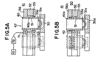
- Figure 5a is a diagrammatic illustration of one embodiment of the present invention which uses an air driven clamp for clamping the mold halves together.
- Figure 5b is a diagrammatic illustration of a second embodiment of the present invention which uses a spring driven clamp for clamping the mold halves together.
- Figure 6 is a plan view of a reciprocating portion of the apparatus for precuring a polymerizable monomer or monomer mixture to form a contact lens.
- Figure 7 is an elevational view of the apparatus illustrated in Figure 6.
- Figure 8 is an end elevational view of the apparatus illustrated in Figure 6.
- the present invention is useful in a process for forming soft contact lenses from a polymerizable monomer or monomer mixture.
- the soft contact lenses are formed in a mold assembly having a first concave and a second convex mold half.
- the mold halves are formed of polystyrene transparent to visible and ultraviolet light, with a central curved section defining a concave surface 31, a convex surface 33 and circular circumferential edge 31(c), and integral with said edge an annular essentially uniplanar flange 31(a).
- At least a part of the concave surface 31 and the convex surface 33 have the dimensions of the front or back curves, respectively of a contact lens to be produced in the mold assembly, and are smooth so that the surface of the contact lens formed by polymerization of said polymerizable composition in contact with the surface is optically acceptable.
- the mold is thin enough to transmit heat therethrough rapidly and has rigidity sufficient to withstand prying forces applied to separate the mold halves during demolding step which occurs after the cure step in the manufacturing process.
- the present invention may be used with an additional precure step introduced between the assembly of the mold with a polymerizable monomer or monomer mixture, and the cure step.
- the precure step partially cures the polymerizable monomer or monomer mixture to a viscous gel and initiates polymerization throughout the mixture.
- the parallel alignment of the mold halves are "frozen” by the viscous gel like nature of the partially polymerized monomer gel which prevents decentration and enables unattended and unweighted cure during the remainder of the cure period.
- the addition of this precure step has substantially reduced the number of defective lenses resulting from traditional methods of manufacture.
- first 31 and second 33 mold halves which define the shape of the final desired lens are used to direct mold the monomer mixture wherein the mixture is dissolved in a nonaqueous water displacable solvent.
- the front concave mold half 31 is substantially filled with a polymerization mixture 32
- the concave front mold half 31 is covered with a base mold half 33 under a vacuum to ensure that no air bubbles are trapped between the mold halves.
- the base mold half is then brought to rest on the circumferential edge 31(c) of the concave front mold half to ensure that the resultant lenses are properly aligned and without distortion.
- the first and second mold halves are then clamped together.
- This clamping step may be done following assembly of the mold halves, during precure, or both.
- the clamping step displaces any surplus monomer from the mold area and properly aligns the mold halves by alignment of the mold flanges.
- the mold halves are clamped under pressure, the monomer or monomer mixture is then exposed to actinic light, preferably from a UV lamp, while the mold halves are clamped.
- actinic light preferably from a UV lamp
- the mold halves are clamped for approximately 40 seconds with 30 seconds of actinic radiation.
- the monomer or monomer mixture has formed a partially polymerized gel, with polymerization initiated throughout the mixture.
- the monomer/diluent mixture is then cured in a UV oven whereby polymerization of the monomer(s) is completed.
- This irradiation with actinic, visible or ultraviolet radiation produces a polymer/diluent mixture in the shape of the final desired hydrogel lens.
- the two halves of the mold are separated in a demolding step typically leaving the contact lens in the first or front curve mold half, from which it is subsequently removed.
- the front and base curve mold halves are used for a single molding and then discarded or disposed of.
- the solvent is displaced with water to produce a hydrated lens, which when fully hydrated and buffered, will be of the final shape and size which, in most cases, is nominally 10% larger than the original molded polymer/diluent article.
- the precure step is inserted in the process immediately after the polymerizable composition is placed in the front curve mold half, and the mold halves assembled.
- compositions to which this precure step may be directed include copolymers based on 2-hydroxyethyl methacrylate ("HEMA”) and one or more comonomers such as 2-hydroxyethyl acrylate, methyl acrylate, methyl methacrylate, vinyl pyrrolidone, N-vinyl acrylamide, hydroxypropyl methacrylate, isobutyl methacrylate, styrene, ethoxyethyl methacrylate, methoxy triethyleneglycol methacrylate, glycidyl methacrylate, diacetone acrylamide, vinyl acetate, acrylamide, hydroxytrimethylene acrylate, methoxyethyl methacrylate, acrylic acid, methacryl acid, glyceryl methacrylate, and dimethylamino ethyl acrylate.
- HEMA 2-hydroxyethyl methacrylate
- comonomers such as 2-hydroxyethyl acrylate, methyl
- compositions are disclosed in U.S. Patent No. 4,495,313 to Larsen, U.S. Patent No. 5,039,459 to Larsen et al. and U.S. Patent No. 4,680,336 to Larsen et al.,.
- Such compositions comprise anhydrous mixtures of a polymerizable hydrophilic hydroxy ester of acrylic acid or methacrylic acid and a polyhydric alcohol, and a water displaceable ester of boric acid and a polyhydroxyl compound having preferably at least 3 hydroxyl groups. Polymerization of such compositions, followed by displacement of the boric acid ester with water, yields a hydrophilic contact lens.
- the mold assembly of the present invention described herein may be used to make hydrophobic or rigid contact lenses, but the manufacture of hydrophilic lenses is preferred.
- the polymerizable compositions preferably contain a small amount of a cross-linking agent, usually from 0.05 to 2% and most frequently from 0.05 to 1.0%, of a diester or triester.
- a cross-linking agent usually from 0.05 to 2% and most frequently from 0.05 to 1.0%, of a diester or triester.
- representative cross linking agents include: ethylene glycol diacrylate, ethylene glycol dimethacrylate, 1,2-butylene dimethacrylate, 1,3-butylene dimethacrylate, 1,4-butylene dimethacrylate, propylene glycol diacrylate, propylene glycol dimethacrylate, diethylglycol dimethacrylate, dipropylene glycol dimethacrylate, diethylene glycol diacrylate, dipropylene glycol diacrylate, glycerine trimethacrylate, trimethylol propane triacrylate, trimethylol propane trimethacrylate, and the like.
- Typical cross-linking agents
- the polymerizable compositions generally also include a catalyst, usually from about 0.05 to 1% of a free radical catalyst.
- a catalyst usually from about 0.05 to 1% of a free radical catalyst.
- Typical examples of such catalysts include lauroyl peroxide, benzoyl peroxide, isopropyl percarbonate, azobisisobutyronitrile and known redox systems such as the ammonium persulfate-sodium metabisulfite combination and the like.
- Irradiation by ultraviolet light, electron beam or a radioactive source may also be employed to catalyze the polymerization reaction, optionally with the addition of a polymerization initiator.
- Representative initiators include camphorquinone, ethyl-4-(N,N-dimethyl-amino)benzoate, and 4-(2-hydroxyethoxy)phenyl-2-hydroxyl-2-propyl ketone.
- Polymerization of the polymerizable composition in the mold assembly is preferably carried out by exposing the composition to polymerization initiating conditions.
- the preferred technique is to include in the composition initiators which work upon expose to ultraviolet or visible radiation; and exposing the composition to ultraviolet or visible radiation of an intensity and duration effective to initiate polymerization and to allow it to proceed.
- the mold halves are preferably transparent to ultraviolet or visible radiation.
- the monomer is again exposed to ultraviolet or visible radiation in a cure step in which the polymerization is permitted to proceed to completion. The required duration of the remainder of the reaction can readily be ascertained experimentally for any polymerizable composition.
- the mold assembly is disassembled to permit further processing of the polymerized hydrogel into a contact lens (such processing including e.g. washing and hydrating, and packaging of the lens).
- a contact lens such processing including e.g. washing and hydrating, and packaging of the lens.
- the flanges of the front and back curve mold halves are gripped and pulled away from each other, either in directly opposite directions or through an angle in a prying sort of motion.
- the back curve is first heated moderately to facilitate separation of the polymerized article from the back curve mold half surfaces.
- Figure 1 and Figure 2 represent a side elevation view and an end elevation view, respectively, of an apparatus for practicing the present invention.
- a support frame 11 having legs 12 provides support for the device at an elevation of an infeed conveyor 13.
- the precure apparatus receives a plurality of pallets, one of which is illustrated in Figure 4, having a plurality of contact lens molds therein, from the infeed conveyor 13.
- the infeed conveyor 13 delivers the pallets 30 and molds 31, 33 to a low oxygen environment, which environment is accomplished by pressurizing an enclosure 14 with nitrogen gas. Prior to polymerization, the monomer is susceptible to absorption of oxygen which results in degradation of the resultant lens.
- the enclosure 14 may be pivoted about pivot point 15 by lifting on handle member 16.
- a gas strut assist device 17 will hold the enclosure 14 in an open position for servicing of the apparatus.
- the conveyor 13 delivers pallets 30 containing a plurality of molds 31,33 to an accumulating section generally indicated 18 which gathers a plurality of pallets for the precure step.
- twelve pallets of the type illustrated in Figure 4 are accumulated for a total of 96 molds in each batch operation.
- a total of 12 pallets having 96 contact lens molds thereon are batched for each precure operation.
- Accumulator 18 thus enables the precure apparatus of the present invention to batch process a plurality of molds for an extended period of time of 30 to 60 seconds while continuously receiving new pallets from the production line at the rate of 1 every 6 to 12 seconds.
- the precure assembly 19 is partially visible in the breakaway portion of Figure 1, and is further described with respect to Figures 6-8. It is raised and lowered into engagement with pallets containing contact lens molds by virtue of a pneumatic cylinder 20 which raises and lowers an intermediate support beam 21 and reciprocating shaft members 22 which are journaled for reciprocating support in member 23 as will be hereinafter subsequently described in greater detail. After the precure operation, the pallets with contact lens molds therein are discharged through a nitrogen ventilation airlock mechanism 24 (illustrated in Figure 1) for subsequent cure by heat and cycled actinic radiation.
- the present invention is particularly adapted to cooperate with a plurality of pallets as illustrated in Figure 4 and 4a which have a plurality of cavities for receiving a plurality of contact lens molds.
- the contact lenses of the present invention are formed by placing an amount of polymerizable composition, generally on the order of about 60 ⁇ l, in the first or concave mold half 31.
- the desired amount depends on the dimensions (i.e., the diameter and thickness) of the desired lens, taking into account the generation of by-products upon polymerization and exchange water for those by-products and diluent, if any, following polymerization.
- a second or convex mold half 33 is placed onto the polymerizable composition 32 with the first and second mold halves aligned so that their axes of rotation are collinear and the respective flanges 31(a), 33(a) are parallel.
- the mold halves 31 are carried in an annular recess 30(a) which receives and supports the annular flange 31(a) of the first or concave mold half.
- the pallet 30 also has a plurality of recesses 30(b) for receiving the concave portion of the mold.
- the pallet also carries a plurality of oriented recesses 30(c) which receive a triangular tab portion 31(c) of the base mold half to provide a predefined angular position.
- the second or convex mold half 33 also includes a triangular tab 33(c) which overlies tab 31(c) to provide a collinear axis of rotation with respect to the two mold halves.
- the pallet 30 illustrated in Figure 4 also contains a unique bar code number 35 for use in pallet tracking and quality control procedures.
- Figure 3 is a diagrammatic representation of a portion of the apparatus more fully illustrated in Figures 6-9 and Figures 9-10 which is particularly suited to an overview of the present invention.
- the apparatus includes a conveyor system 13 for transporting a plurality of pallets 30 into and away from the precure station.
- Batch mode forks 36(a), 36(b) are used to gather and move a plurality of pallets into the precure apparatus.
- the apparatus 19 includes multiple vertical reciprocal movements, a first one of which is in response to movement from air cylinder 20(a) and reciprocating beam 21(a).
- a plurality of annular clamping means 40 will engage the upper annular flange 33(a) of each of the mold halves contained within pallets 30.
- a plurality of annular clamping means 40 are mounted on and travel with a reciprocating platform 41 of the apparatus, and are resiliently mounted therein for a second reciprocal movement along the directions of arrow B illustrated in Figure 3.
- the clamping means 40 are biased within frame 41 by springs 42 (illustrated diagrammatically) which may be the air spring 42(a) illustrated in Figure 5a or a helical spring 42 as illustrated in Figure 5b.
- springs 42 illustrated diagrammatically
- the clamping means will engage and clamp the first and second mold halves together with the force determined by the spring means 42.
- the force will be determined by the amount of pressure provided to the air cylinder 42(a). While clamping means 40 have been illustrated as four members in Figure 3 for illustrative purposes, it is understood that in the embodiments illustrated in Figure 6-8 and the embodiment illustrated in Figures 9-10 that there are 96 individual clamping means, with an individual clamping means for each of the mold halves.
- a plurality of actinic light sources 44 Positioned above the clamping apparatus are a plurality of actinic light sources 44 which may be UV lamps.
- the lamps are separated from the clamping area by Pyrex glass 100 which separates the precure apparatus into two separate heat zones. This enables cooling of the actinic lamps 44, while maintaining the clamping zone at an optimal cure temperature.
- the glass 100 also protects the lamps from monomer emissions which collect on the glass 100 rather than the lamps 44.
- a shutter mechanism 45 is opened by air cylinder 46 to enable the actinic light source 44 to initiate polymerization of the polymerizable composition in each of the mold halves 33.
- Shutter 45 has a plurality of openings 43 defined therein and is reciprocal along the x axis as indicated by arrow C in Figure 3 in order to open and close the exposure passage ways 47.
- control circuit 10 which controls the duration of the clamping period by the length of time air cylinder 20(a) is activated to its reciprocal down position.
- Control circuit 10 also controls the amount of radiation received by the molds controlling the duration of the exposure period through operation of shutter 45 and air cylinder 46.
- the intensity may also be manually adjusted by raising or lowering the lamps 44 with respect to molds 31,33.
- the polymerization radiation may be generated remotely and routed to the clamped mold halves and polymerizable material via a fiber optic system, with control system 10 providing control of exposure time and energy level.
- the amount of force applied by clamping means 40 may be varied from approximately 4.903 to 19.613 N/per lens (0.5 Kgf to 2.0 Kgf/per lens) and is applied to keep the flange 33(a) of the second convex mold half parallel to the flange 31(a) of the first concave mold half for the duration of the exposure.
- the clamping weight is applied for 10 to 60 seconds, but typically for a period of 40 seconds by control means 10.
- actinic radiation from UV lamps 44 is applied to the assembled mold and the polymerizable monomer.
- the intensity of the UV light source is 2-4 mW/cm 2 , and this intensity of light is applied for 10 to 50 seconds, but in the preferred embodiment, is applied for 30 seconds.
- the UV lamp source are tubular low pressure mercury vapor fluorescent lamps which emit a long wave ultraviolet radiation having a highly concentrated radiation between 320 and 390 nm.
- the lamps are manufactured by Philips as model TL' 29 D 16/09 N having a nominal wattage of 14 watts and an average radiation of 1.8 watts in the desired spectrum.
- the mold halves are first clamped together for a predetermined period of time, prior to exposure, in order to allow equilibrium to develop between the monomer and the mold cavity, and to allow any excess monomer to be extruded out of the mold cavity into the space between flanges 31(a) and 32(a) where it forms a ring of excess monomer 32(a), which is generally referred to as a "HEMA" ring when hydroxyethylmethacrylate monomer is used.
- the first or concave mold cavity includes a sharp annular edge 31(c) to cleanly contact the convex portion of mold half 33 and thereby separate the contact lens 32 from the HEMA ring 32(a).
- the pre-exposure clamping period allows for any excess monomer to migrate from the mold cavity to the HEMA ring, enables the second mold cavity to seat cleanly on parting edge 31(c), and allows an equilibrium to develop between the mold halves and the monomer.
- actinic radiation on the order of 2-4 mW/cm 2 is applied for approximately 30 seconds.
- Different intensities and exposure times could be used, including pulsed and cycled high intensity UV on the order of 10 to 150 mW/cm 2 with exposure times running from 5 to 60 seconds.
- the actinic-radiation may be cycled on for 3 to 10 seconds and then off for 3 to 10 seconds with a total of 1 to 10 cycles of radiation.
- the shutter 45 is closed by reciprocating it to the right as illustrated in Figure 3 and the weight is removed by energizing cylinder 20(a) to lift the precure assembly 19 upwardly by means of push rods 22(a).
- the clamping means 40 will be lifted clear of the molds and pallets to enable them to be transported out of the precure means by means of conveyor 13(a).
- the temperature in the system may be varied from ambient to 50°C.
- the monomer has gone through initiation and some degree of polymerization.
- the resultant product is in a gel state with some areas of the product that have the least thickness, i.e., the edge, having a higher degree of polymerization than the body.
- the monomer polymerizes it forms a seal along the parting edge 31(c), which together with the inherent shrinkage of the monomer from polymerization, forms a secure mold package that may be cured in atmospheric conditions.
- the clamping pressure aligns the mold flanges to provide substantially parallel alignment of the flanges, and the seal maintains them in a parallel position which results in improved optical characteristics near the theoretical maximum of the plastic mold halves. Further, the clamping, and resultant seal from the partial cure results in an improved "clean" edge at the circumference of the lens.
- Figures 5a and 5b are schematic illustrations of two alternate means for clamping the mold halves together.
- an air spring is used to displace the clamping means 40 downwardly with respect to the movement of reciprocating platform 41.
- a resilient coil spring 42 is used to drive the clamping means 40 downwardly with respect to the movement of reciprocating platform 41.
- reciprocating platform 41 includes a plurality of annular cylinders 40, each of which has an annular flange 51 formed thereon, which reciprocates within a cylinder defined by spacer plate 52 to form an air spring or air cylinder 42(a).
- the cylinder is vented to atmosphere by vents, one of which is illustrated at 53 in Figure 5a to enable air pressure in the air cylinder 42(a) to drive the flange 51 and clamping means 40 downwardly against a stop plate 55 when the air cylinder 42(a) is pressurized.
- the carriage 50 also includes an upper stop member 56 which defines the upper limit of travel by annular flange 51, and serves as reciprocal bearing support for the clamping means 40.
- the upper stop member 56 also defines a plurality of air plenums, one of which is schematically illustrated at 71, which provide air pressure for the air cylinder 42(a).
- Air pressure is supplied to plenum 71 by solenoid air valve 72 which is activated by control means 10.
- the air pressure supplied to air cylinder 42(a) is variable to generate a clamping force of 4.903 to 19.613 N/per lens (0.5 Kgf to 2.0 Kgf) on the annular flange 33(a).
- the annular clamping means 40 engages the annular flange 33(a) formed on the second or convex mold half to urge it downwardly and clamp it into engagement with mold half 31.
- the movement of reciprocating platform 41 is defined by the movement of the entire assembly 19 as driven by air cylinder 20.
- the annular clamping cylinder 40 also includes an annular flange 51 which is engaged by a resilient coil spring 42 and driven downwardly, as illustrated in Figure 5b, against stop plate 55.
- the other end of coil spring 42 is mounted within upper stop plate 56(a).
- Spacer plate 52 and the upper stop plate 56 provide support and guidance for the vertical reciprocation of clamping members 40.
- the clamping member 40 is formed of stainless steel, and optionally the mass of the clamping members may be increased to enable the clamping members to clamp by weight alone, without air or spring assist.
- the combination of the individual reciprocal clamping means 40 and locally driven resilient biasing means enable precise control of the amount of clamping pressure exerted on the plastic flanges 33(a) of the upper mold regardless of the amount of force needed to move the mass of the entire precure assembly 19.
- Figures 6-8 are top side and end elevation views of one embodiment of the apparatus for performing the present invention.
- the precure assembly 19 is mounted on reciprocating support shafts 22 which are journaled for reciprocating motion within support members 23 which are fixably mounted to a frame.
- Each of the support members 23 include upper and lower bearings or journals 23(a), 23(b) to provide for precision guidance of the reciprocating shafts 22.
- Shafts 22 are driven by intermediate support frame 21 which is in turn driven by air cylinder 20 as previously described.
- the precure assembly 19 is reciprocated vertically with respect to the upper most surface of the conveyor 13 illustrated schematically in Figures 7 and 8.
- the precure assembly 19 is supported from an upper support frame 60 from which various operating components are suspended by intermediate support members at each corner generally illustrated at 61, 62 in Figure 7 and 62, 63 in Figure 8. These members suspend the reciprocating platform 41, into which the individual clamping means 40 are fitted for a secondary reciprocation along the same axis.
- a separate subframe 65 is mounted on platform 41 and provides support for the ultraviolet lamps 44 and the ballast members 66 which provide the high voltage for the UV lamps, and the starters 67 which are used to initiate fluorescence.
- the ballast members may be BTP 30C05S, as manufactured by Philips and the starters may be model S2, as manufactured by Philips.
- the intermediate support frame 65 may be lifted free from the reciprocating platform 41 by means of a plurality of handles 67 which are mounted via straps 68 to the intermediate support frame 65.
- Pyrex glass member 100 separates the lamps 44 from the clamping area to protect the lamps from monomer emissions, and to enable the lamps to be cooled, while keeping the precure zone at a temperature of ambient to 50°C to facilitate polymerization.
- An oxygen detector 69 is also provided to monitor the low oxygen environment maintained within the protective cabinet 14 and an alarm is initiated if the oxygen content rises to an unacceptable level.
- Shutter 45 is positioned above the reciprocating platform 41 between the UV lamps 44 and the clamping means 40 and is reciprocated between its open and closed position by virtue of air cylinder 46.
- FIG. 6-8 utilizes the air cylinder or air springs depicted schematically in Figure 5a with an internal common plenum formed in the reciprocating platform 41 by means of passageways in stop plate 56.
- each of the 96 clamping members 40 are reciprocated by their respective air cylinders, which are fed from common plenums, one of which is illustrated in Figure 5a as plenum 71 formed in the upper stop plate 56.
Landscapes
- Engineering & Computer Science (AREA)
- Health & Medical Sciences (AREA)
- Mechanical Engineering (AREA)
- Manufacturing & Machinery (AREA)
- Ophthalmology & Optometry (AREA)
- Thermal Sciences (AREA)
- Physics & Mathematics (AREA)
- Oral & Maxillofacial Surgery (AREA)
- Toxicology (AREA)
- Eyeglasses (AREA)
- Casting Or Compression Moulding Of Plastics Or The Like (AREA)
- Materials For Medical Uses (AREA)
- Dental Preparations (AREA)
- Moulds For Moulding Plastics Or The Like (AREA)
- Heating, Cooling, Or Curing Plastics Or The Like In General (AREA)
- Macromonomer-Based Addition Polymer (AREA)
Claims (43)
- Dispositif pour durcir partiellement un monomère ou mélange de monomères polymérisable dans le cadre d'un processus destiné à façonner une lentille de contact souple, ledit dispositif comprenant :a) un élément de serrage (40) pour serrer une première moitié de moule de lentille de contact contre une deuxième moitié de moule de lentille de contact à une station de prédurcissement (19) à une pression prédéterminée et pendant une période de temps prédéterminée, lesdites première et deuxième moitiés de moule (31, 33) ayant un monomère ou mélange de monomères polymérisable entre elles, et dans lequel ladite pression d'élément de serrage aligne les moitiés de moule pour les maintenir en position parallèle ;b) une source d'énergie radiante (44) pour générer une énergie radiante et diriger ladite énergie radiante sur ledit monomère ou mélange de monomères pendant que lesdites première et deuxième moitiés de moule (31, 33) sont serrées ensemble pour initialiser la polymérisation, dans lequel ladite source d'énergie radiante (44) est mobile d'une première position de transport à une deuxième position de pose pour polymériser ledit monomère ou mélange de monomères ;c) un bâti (65) pour déplacer ladite source de lumière radiante (44) de ladite position de transport à ladite position de pose, dans lequel ledit élément de serrage (40) est installé sur ledit bâti (65) et vient en prise de façon élastique avec ladite deuxième moitié de moule au fur et à mesure que la source d'énergie radiante est déplacée jusqu'à ladite position de pose.
- Dispositif pour durcir partiellement un monomère ou mélange de monomères polymérisable selon la revendication 1, dans lequel ledit dispositif comprend en outre des moyens de transport (13) pour transporter de façon intermittente une pluralité de moitiés de moule de lentille de contact (31, 33) à destination et en provenance de ladite station de prédurcissement (19) .
- Dispositif selon la revendication 1, dans lequel chacune des première et deuxième moitiés de moule comporte une bride et une surface courbe, et l'élément de serrage impose l'alignement de celles-ci pour assurer que les brides sont parallèles et que les surfaces courbes respectives des moitiés de moule sont alignées.
- Dispositif selon la revendication 1, dans lequel la première moitié de moule a un bord annulaire, la surface courbe de la deuxième moitié de moule est une surface de forme convexe, et l'élément de serrage (40) oblige également la deuxième moitié de moule à se placer contre ledit bord annulaire sur la première moitié de moule pour sectionner du monomère excédentaire du monomère entre les moitiés de moule (31, 33).
- Dispositif pour durcir partiellement un monomère ou mélange de monomères polymérisable selon la revendication 1, dans lequel ledit élément de serrage (40) comprend un élément de serrage alternatif positionné entre ladite deuxième moitié de moule et ladite source d'énergie radiante (44).
- Dispositif pour durcir partiellement un monomère ou mélange de monomères polymérisable selon la revendication 5, dans lequel ledit élément de serrage (40) comprend un cylindre annulaire ayant un diamètre annulaire supérieur au diamètre de la lentille de contact à polymériser.
- Dispositif pour durcir partiellement un monomère ou mélange de monomères polymérisable selon la revendication 6, dans lequel ledit cylindre annulaire est incliné pour venir en prise avec ledit moule.
- Dispositif pour durcir partiellement un monomère ou mélange de monomères polymérisable selon la revendication 7, dans lequel la pression d'inclinaison est de 4,903 à 19,613 N/ par lentille (0,5 à 2,0 kgf/lentille) de force de serrage.
- Dispositif pour durcir partiellement un monomère ou mélange de monomères polymérisable selon la revendication 1, dans lequel ledit bâti (65) comprend une monture fixe pour une pluralité de lampes qui émettent une radiation actinique, ladite monture pouvant alterner entre une position de transport et une position de pose.
- Dispositif pour durcir partiellement un monomère ou mélange de monomères polymérisable selon la revendication 9, dans lequel ladite radiation actinique est émise par des lampes-UV à 320 à 390 nm.
- Dispositif pour durcir partiellement un monomère ou mélange de monomères polymérisable selon la revendication 2, dans lequel lesdits moyens de transport (13) comprennent un porte-moule pour transporter une pluralité de moitiés de moule (31, 33) jusqu'à ladite position de pose.
- Dispositif pour durcir partiellement un monomère ou mélange de monomères polymérisable selon la revendication 11, dans lequel lesdits des moyens de transport sont arrêtés de façon intermittente quand ladite source ultraviolette est déplacée jusqu'à la deuxième position de pose.
- Dispositif pour durcir partiellement un monomère ou mélange de monomères polymérisable selon la revendication 9, dans lequel ladite source de lumière ultraviolette comprend une pluralité de lampes-UV, chaque lampe (44) ayant un axe longitudinal, dans lequel une pluralité de moitiés de moule (31, 33) est alignée sur ledit axe longitudinal pendant ladite pose.
- Dispositif selon l'une quelconque des revendications précédentes, dans lequel ledit dispositif comprend en outre un circuit de commande pour commander la quantité d'énergie reçue par ledit monomère ou mélange de monomères pendant ladite étape de pose.
- Procédé de prédurcissement d'un monomère ou mélange de monomères polymérisable dans le cadre d'un processus destiné à façonner une lentille de contact souple, le procédé comprenant les étapes consistant à :a) prévoir un moule de lentille de contact ayant des première et deuxième moitiés de moule (31, 33) ;b) déposer un monomère ou mélange de monomères polymérisable dans le moule de lentille de contact, entre lesdites première et deuxième moitiés de moule (31, 33) ;c) déplacer une source de lumière actinique d'une première position de transport à une deuxième position de pose, ladite source de lumière étant déplacée au moyen d'un bâti (65) ;d) serrer la première moitié de moule contre la deuxième moitié de moule, le monomère ou mélange de monomères polymérisable se trouvant entre les deux, à une pression de serrage prédéterminée et pendant une période de temps prédéterminée, dans lequel ladite pression de serrage aligne correctement les moitiés de moule et ledit serrage est assuré par un élément de serrage (40) installé sur ledit bâti (65), ledit élément de serrage venant en prise de façon élastique avec ladite deuxième moitié de moule au fur et à mesure que ladite source d'énergie radiante est déplacée jusqu'à ladite position de pose ;e) exposer le monomère ou le mélange de monomères à la radiation pour initialiser la polymérisation et pour polymériser partiellement ledit monomère ou mélange de monomères en un gel visqueux dans l'ensemble du monomère ou mélange de monomères.
- Procédé selon la revendication 15, dans lequel les étapes (b) à (d) sont menées dans un environnement pauvre en oxygène.
- Procédé de durcissement partiel d'un monomère ou mélange de monomères polymérisable selon la revendication 15, dans lequel ledit monomère est exposé à une source d'énergie actinique, à faisceau d'électrons ou radioactive.
- Procédé de durcissement partiel d'un monomère ou mélange de monomères polymérisable selon la revendication 17, dans lequel ladite source d'énergie est une lampe-UV (44).
- Procédé de durcissement partiel d'un monomère ou mélange de monomères polymérisable selon la revendication 18, dans lequel ledit monomère est exposé à 2 à 150 mW/cm2 de radiation ultraviolette à une longueur d'onde de 320 à 390 nm.
- Procédé de durcissement partiel d'un monomère ou mélange de monomères polymérisable selon la revendication 18, dans lequel ledit monomère est exposé à 2,4 mW/cm2 de radiation ultraviolette à une longueur d'onde de 350 nm.
- Procédé de durcissement partiel d'un monomère ou mélange de monomères polymérisable selon la revendication 19, dans lequel ladite radiation de prédurcissement est définie pour une période de temps de 1 à 60 secondes.
- Procédé de durcissement partiel d'un monomère ou mélange de monomères polymérisable selon la revendication 20, dans lequel ladite étape de radiation de prédurcissement dure de 20 à 40 secondes.
- Procédé de durcissement partiel d'un monomère ou mélange de monomères polymérisable selon la revendication 15, dans lequel la force exercée pendant l'étape de serrage varie de 4,903 à 19,613 N/ par lentille (0,5 à 2,0 kgf/ par lentille).
- Procédé selon la revendication 15 de durcissement partiel d'un monomère ou mélange de monomères polymérisable pour façonner une lentille de contact souple, ledit procédé comprenant en outre les étapes consistant à :e) transférer le moule de lentille jusqu'à une station de durcissement final ; etf) à la station de durcissement final, polymériser le monomère ou mélange de monomères jusqu'à un état durci.
- Procédé selon la revendication 15, dans lequel une pluralité de moules de lentille de contact est transportée de façon intermittente à travers une station de prédurcissement (19), ledit procédé comprenant en outre l'étape consistant à utiliser un circuit de commande (10) pour définir lesdites pression et durée prédéterminées.
- Procédé de durcissement partiel d'un monomère ou mélange de monomères polymérisable selon la revendication 25, dans lequel le circuit de commande (10) comprend en outre des moyens pour faire varier la quantité d'énergie reçue par ledit monomère pendant ladite étape de pose.
- Procédé de durcissement partiel d'un monomère ou mélange de monomères polymérisable selon la revendication 25, dans lequel ledit circuit de commande (10) commande la durée de la pose.
- Procédé de durcissement partiel d'un monomère ou mélange de monomères polymérisable selon la revendication 25, dans lequel l'élément de serrage (40) est positionné entre les moules et la source d'énergie radiante (44).
- Procédé de durcissement partiel d'un monomère ou mélange de monomères polymérisable selon la revendication 25, dans lequel l'étape de transport comprend l'étape d'utilisation de moyens de transport (13) pour déplacer les moules de lentille de contact, et lesdits moyens de transport peuvent être déplacés d'une première position de transport à une deuxième position de pose pour polymériser ledit monomère.
- Procédé de durcissement partiel d'un monomère ou mélange de monomères polymérisable selon la revendication 29, dans lequel l'étape de serrage comprend l'étape d'utilisation d'un élément de serrage (40) pour appliquer la pression de serrage, et ledit élément de serrage est installé de façon élastique et lesdits moyens de transport (13) déplacent lesdits moules pour venir en prise de façon élastique avec ledit élément de serrage (40) au fur et à mesure que lesdits moules sont déplacés jusqu'à ladite position de pose.
- Procédé de durcissement partiel d'un monomère ou mélange de monomères polymérisable selon la revendication 28, dans lequel ledit élément de serrage (40) comprend un cylindre annulaire ayant un diamètre annulaire supérieur au diamètre de la lentille de contact à polymériser.
- Procédé de durcissement partiel d'un monomère ou mélange de monomères polymérisable selon la revendication 31, dans lequel ledit cylindre annulaire est incliné de façon élastique pour venir en prise avec ledit moule.
- Procédé de durcissement partiel d'un monomère ou mélange de monomères polymérisable selon la revendication 32, dans lequel ladite pression de serrage va de 4,903 à 19,613 N/ par lentille (0,5 à 2,0 kgf/ par lentille).
- Procédé de durcissement partiel d'un monomère ou mélange de monomères polymérisable selon la revendication 25, dans lequel l'étape de pose comprend l'étape d'utilisation d'une monture fixe pour une pluralité de lampes (44) qui émettent une radiation actinique, et l'étape de transport comprend l'étape d'utilisation de moyens de transport (13) pour déplacer les moules de lentille de contact, lesdits moyens de transport pouvant alterner entre une position de transport et une position de pose.
- Procédé de durcissement partiel d'un monomère ou mélange de monomères polymérisable selon la revendication 34, dans lequel ladite radiation actinique est émise par une lampe-UV à 320 à 390 nm.
- Procédé de durcissement partiel d'un monomère ou mélange de monomères polymérisable selon la revendication 25, dans lequel l'étape de serrage comprend l'étape d'utilisation d'une pluralité d'éléments de serrage (40) pour appliquer la pression de serrage, et l'étape de transport comprend l'étape d'utilisation d'une pluralité de palettes de moule (30) pour transporter une pluralité de moitiés de moule (31, 33) jusqu'à ladite position de pose.
- Procédé de durcissement partiel d'un monomère ou mélange de monomères polymérisable selon la revendication 36, dans lequel on fait alterner lesdits moyens de palettes (30) de façon intermittente en direction de ladite source ultraviolette (44) jusqu'à ladite deuxième position de pose.
- Procédé de durcissement partiel d'un monomère ou mélange de monomères polymérisable selon la revendication 37, dans lequel l'étape de transport comprend l'étape d'utilisation d'une pluralité de colonnes de levage pour soulever lesdites palettes (30) pour venir en prise avec ladite pluralité d'éléments de serrage (40) .
- Procédé de durcissement partiel d'un monomère ou mélange de monomères polymérisable selon la revendication 38, dans lequel ledit élément de serrage (40) comprend un élément de serrage annulaire positionné entre lesdites colonnes de levage et ladite source d'énergie radiante (44).
- Procédé de durcissement partiel d'un monomère ou mélange de monomères polymérisable selon la revendication 39, dans lequel ledit élément de serrage (40) est incliné de façon élastique et se déplace d'une position de mise en prise jusqu'à une position de pose lors du serrage desdites moitiés de moule (31, 33).
- Procédé selon la revendication 25, dans lequel chacune des moitiés de moule (31, 33) comprend une bride respective (31a, 33a), les premières moitiés de moule comprennent des surfaces courbes concaves et les deuxièmes moitiés de moule comprennent des surfaces courbes convexes, et dans lequel la pression de serrage impose l'alignement des brides (31a, 33a) des première et deuxième moitiés de moule de chaque moule pour assurer que les brides sont parallèles et que les surfaces courbes respectives des moitiés de moule (31, 33) du moule sont alignées.
- Procédé selon la revendication 25, dans lequel la première moitié de moule de chaque moule comporte une bride annulaire (31a, 33a), et la pression de serrage oblige également la deuxième moitié de moule de chaque moule à se placer contre le bord annulaire de la première moitié de moule du moule de lentille pour sectionner du monomère excédentaire du monomère entre les moitiés de moule (31, 33) du moule.
- Procédé de durcissement d'un monomère ou mélange de monomères polymérisable selon la revendication 42, dans lequel ladite étape de serrage forme un bord de lentille net pour ladite lentille de contact.
Applications Claiming Priority (2)
| Application Number | Priority Date | Filing Date | Title |
|---|---|---|---|
| US25779294A | 1994-06-10 | 1994-06-10 | |
| US257792 | 1994-06-10 |
Publications (3)
| Publication Number | Publication Date |
|---|---|
| EP0686483A2 EP0686483A2 (fr) | 1995-12-13 |
| EP0686483A3 EP0686483A3 (fr) | 1996-11-27 |
| EP0686483B1 true EP0686483B1 (fr) | 2002-09-18 |
Family
ID=22977767
Family Applications (1)
| Application Number | Title | Priority Date | Filing Date |
|---|---|---|---|
| EP95303985A Expired - Lifetime EP0686483B1 (fr) | 1994-06-10 | 1995-06-09 | Fermeture d'un moule et prédurcissement d'un hydrogel polymérisable |
Country Status (11)
| Country | Link |
|---|---|
| US (1) | US5914074A (fr) |
| EP (1) | EP0686483B1 (fr) |
| JP (1) | JP4094071B2 (fr) |
| AT (1) | ATE224293T1 (fr) |
| AU (1) | AU708945B2 (fr) |
| BR (1) | BR9502730A (fr) |
| CA (1) | CA2151341C (fr) |
| CZ (1) | CZ147495A3 (fr) |
| DE (1) | DE69528211T2 (fr) |
| IL (1) | IL113904A0 (fr) |
| ZA (1) | ZA954802B (fr) |
Families Citing this family (73)
| Publication number | Priority date | Publication date | Assignee | Title |
|---|---|---|---|---|
| AU6658698A (en) * | 1997-02-20 | 1998-09-09 | Technology Resource International Corporation | Gasket for lens making |
| US5989462A (en) * | 1997-07-31 | 1999-11-23 | Q2100, Inc. | Method and composition for producing ultraviolent blocking lenses |
| US6103148A (en) * | 1998-02-19 | 2000-08-15 | Technology Resources International Corporation | Method for curing a lens-forming fluid |
| US6416307B1 (en) | 1998-09-25 | 2002-07-09 | Q2100, Inc. | Plastic lens systems, compositions, and methods |
| US6511311B1 (en) * | 1998-09-30 | 2003-01-28 | Novartis Ag | Lens mold carriers |
| US20040112008A1 (en) | 1998-12-21 | 2004-06-17 | Voss Leslie A. | Heat seal apparatus for lens packages |
| US20070157553A1 (en) * | 1998-12-21 | 2007-07-12 | Voss Leslie A | Heat seal apparatus for lens packages |
| US6207086B1 (en) | 1999-02-18 | 2001-03-27 | Johnson & Johnson Vision Care, Inc. | Method and apparatus for washing or hydration of ophthalmic devices |
| US6419873B1 (en) | 1999-03-19 | 2002-07-16 | Q2100, Inc. | Plastic lens systems, compositions, and methods |
| SE9902131L (sv) * | 1999-06-08 | 2000-12-09 | Nolato Silikonteknik Ab | Metod och anordning för framställning av ett elastiskt element samt komponent innefattande sådant elastiskt element |
| WO2001000393A2 (fr) * | 1999-06-25 | 2001-01-04 | Novartis Ag | Dispositif d'illumination uv |
| USD434050S (en) * | 1999-12-06 | 2000-11-21 | Technology Resource International Corporation | Gasket for lens making |
| US6630083B1 (en) | 1999-12-21 | 2003-10-07 | Johnson & Johnson Vision Care, Inc. | Methods and compositions for the manufacture of ophthalmic lenses |
| US6723260B1 (en) | 2000-03-30 | 2004-04-20 | Q2100, Inc. | Method for marking a plastic eyeglass lens using a mold assembly holder |
| AU2001249721A1 (en) * | 2000-03-30 | 2001-10-15 | Q 2100, Inc. | Gasket and mold assembly for producing plastic lenses |
| US6698708B1 (en) | 2000-03-30 | 2004-03-02 | Q2100, Inc. | Gasket and mold assembly for producing plastic lenses |
| US6960312B2 (en) | 2000-03-30 | 2005-11-01 | Q2100, Inc. | Methods for the production of plastic lenses |
| US6528955B1 (en) | 2000-03-30 | 2003-03-04 | Q2100, Inc. | Ballast system for a fluorescent lamp |
| US6716375B1 (en) | 2000-03-30 | 2004-04-06 | Q2100, Inc. | Apparatus and method for heating a polymerizable composition |
| AU2001238306A1 (en) * | 2000-03-31 | 2001-10-15 | Bausch And Lomb Incorporated | Method and device to control polymerization |
| AU2001252985A1 (en) | 2000-03-31 | 2001-10-15 | Bausch And Lomb Incorporated | Methods and devices to control polymerization |
| US6514436B1 (en) | 2000-05-31 | 2003-02-04 | Bausch & Lomb Incorporated | Apparatus and method for clamping and releasing contact lens molds |
| US6632535B1 (en) | 2000-06-08 | 2003-10-14 | Q2100, Inc. | Method of forming antireflective coatings |
| US7037449B2 (en) | 2001-02-20 | 2006-05-02 | Q2100, Inc. | Method for automatically shutting down a lens forming apparatus |
| US6702564B2 (en) | 2001-02-20 | 2004-03-09 | Q2100, Inc. | System for preparing an eyeglass lens using colored mold holders |
| US7052262B2 (en) | 2001-02-20 | 2006-05-30 | Q2100, Inc. | System for preparing eyeglasses lens with filling station |
| US6752613B2 (en) | 2001-02-20 | 2004-06-22 | Q2100, Inc. | Apparatus for preparing an eyeglass lens having a controller for initiation of lens curing |
| US6790022B1 (en) | 2001-02-20 | 2004-09-14 | Q2100, Inc. | Apparatus for preparing an eyeglass lens having a movable lamp mount |
| US7004740B2 (en) | 2001-02-20 | 2006-02-28 | Q2100, Inc. | Apparatus for preparing an eyeglass lens having a heating system |
| US7025910B2 (en) | 2001-02-20 | 2006-04-11 | Q2100, Inc | Method of entering prescription information |
| US6840752B2 (en) * | 2001-02-20 | 2005-01-11 | Q2100, Inc. | Apparatus for preparing multiple eyeglass lenses |
| US6676398B2 (en) | 2001-02-20 | 2004-01-13 | Q2100, Inc. | Apparatus for preparing an eyeglass lens having a prescription reader |
| US6676399B1 (en) | 2001-02-20 | 2004-01-13 | Q2100, Inc. | Apparatus for preparing an eyeglass lens having sensors for tracking mold assemblies |
| US6758663B2 (en) | 2001-02-20 | 2004-07-06 | Q2100, Inc. | System for preparing eyeglass lenses with a high volume curing unit |
| US6962669B2 (en) | 2001-02-20 | 2005-11-08 | Q2100, Inc. | Computerized controller for an eyeglass lens curing apparatus |
| US6709257B2 (en) | 2001-02-20 | 2004-03-23 | Q2100, Inc. | Eyeglass lens forming apparatus with sensor |
| US7139636B2 (en) * | 2001-02-20 | 2006-11-21 | Q2100, Inc. | System for preparing eyeglass lenses with bar code reader |
| US7074352B2 (en) | 2001-02-20 | 2006-07-11 | Q2100, Inc. | Graphical interface for monitoring usage of components of a lens forming apparatus |
| US6893245B2 (en) | 2001-02-20 | 2005-05-17 | Q2100, Inc. | Apparatus for preparing an eyeglass lens having a computer system controller |
| US6655946B2 (en) | 2001-02-20 | 2003-12-02 | Q2100, Inc. | Apparatus for preparing an eyeglass lens having a controller for conveyor and curing units |
| US6808381B2 (en) | 2001-02-20 | 2004-10-26 | Q2100, Inc. | Apparatus for preparing an eyeglass lens having a controller |
| US6863518B2 (en) | 2001-02-20 | 2005-03-08 | Q2100, Inc. | Mold filing apparatus having multiple fill stations |
| US6875005B2 (en) | 2001-02-20 | 2005-04-05 | Q1200, Inc. | Apparatus for preparing an eyeglass lens having a gating device |
| US6726463B2 (en) | 2001-02-20 | 2004-04-27 | Q2100, Inc. | Apparatus for preparing an eyeglass lens having a dual computer system controller |
| US7045081B2 (en) | 2001-02-20 | 2006-05-16 | Q2100, Inc. | Method of monitoring components of a lens forming apparatus |
| US7060208B2 (en) | 2001-02-20 | 2006-06-13 | Q2100, Inc. | Method of preparing an eyeglass lens with a controller |
| US7124995B2 (en) * | 2001-02-20 | 2006-10-24 | Q2100, Inc. | Holder for mold assemblies and molds |
| US7051290B2 (en) * | 2001-02-20 | 2006-05-23 | Q2100, Inc. | Graphical interface for receiving eyeglass prescription information |
| US6712331B2 (en) | 2001-02-20 | 2004-03-30 | Q2100, Inc. | Holder for mold assemblies with indicia |
| US7011773B2 (en) | 2001-02-20 | 2006-03-14 | Q2100, Inc. | Graphical interface to display mold assembly position in a lens forming apparatus |
| US6790024B2 (en) | 2001-02-20 | 2004-09-14 | Q2100, Inc. | Apparatus for preparing an eyeglass lens having multiple conveyor systems |
| US7083404B2 (en) * | 2001-02-20 | 2006-08-01 | Q2100, Inc. | System for preparing an eyeglass lens using a mold holder |
| US6612828B2 (en) | 2001-02-20 | 2003-09-02 | Q2100, Inc. | Fill system with controller for monitoring use |
| US6899831B1 (en) | 2001-02-20 | 2005-05-31 | Q2100, Inc. | Method of preparing an eyeglass lens by delayed entry of mold assemblies into a curing apparatus |
| SE0101702D0 (sv) * | 2001-05-15 | 2001-05-15 | Ardenia Investments Ltd | Novel potentiating compounds |
| US7368072B2 (en) * | 2001-12-10 | 2008-05-06 | Ppg Industries Ohio, Inc. | Photochromic contact lenses and methods of manufacturing |
| US7044429B1 (en) | 2002-03-15 | 2006-05-16 | Q2100, Inc. | Methods and systems for coating eyeglass lens molds |
| US6464484B1 (en) | 2002-03-30 | 2002-10-15 | Q2100, Inc. | Apparatus and system for the production of plastic lenses |
| DE10242719A1 (de) * | 2002-09-13 | 2004-03-18 | Cetelon Lackfabrik Walter Stier Gmbh & Co.Kg | Vorrichtung zur Härtung strahlungshärtbarer Beschichtungen |
| US20080131593A1 (en) * | 2004-01-29 | 2008-06-05 | Powell P Mark | Contact lens mold printing systems and processes |
| US20060043623A1 (en) * | 2004-08-27 | 2006-03-02 | Powell P M | Masked precure of ophthalmic lenses: systems and methods thereof |
| WO2007090078A1 (fr) * | 2006-02-01 | 2007-08-09 | Johnson & Johnson Vision Care, Inc. | Commande d'axe dans la production de verres de contact toriques |
| CN101037013A (zh) * | 2006-03-15 | 2007-09-19 | 鸿富锦精密工业(深圳)有限公司 | 模具装置 |
| US20080185744A1 (en) * | 2007-02-01 | 2008-08-07 | Bausch & Lomb Incorporated | Thermal Conductive Curing of Ophthalmic Lenses |
| SG168419A1 (en) * | 2009-07-10 | 2011-02-28 | Menicon Co Ltd | Systems and methods for the production of contact lenses |
| EP2637847B1 (fr) | 2010-11-10 | 2014-07-23 | Novartis AG | Procédé pour fabriquer des lentilles de contact |
| US20130235334A1 (en) * | 2011-08-31 | 2013-09-12 | Michael F. Widman | Ophthalmic lens forming optic |
| US9233511B2 (en) * | 2012-05-10 | 2016-01-12 | Optiz, Inc. | Method of making stamped multi-layer polymer lens |
| US11480714B2 (en) | 2017-10-04 | 2022-10-25 | University Of Florida Research Foundation, Inc. | Methods and compositions for improved comfort contact lens |
| EP3840925B1 (fr) * | 2018-08-24 | 2022-11-23 | PPG Industries Ohio Inc. | Procédé de préparation d'un article polymère moulé |
| US11408589B2 (en) | 2019-12-05 | 2022-08-09 | Optiz, Inc. | Monolithic multi-focus light source device |
| EP4000874B1 (fr) * | 2020-11-23 | 2023-10-04 | KOCH Pac-Systeme GmbH | Procédé et dispositif de fabrication et d'essai d'un emballage |
| WO2023117075A1 (fr) * | 2021-12-22 | 2023-06-29 | Transitions Optical, Ltd. | Appareil de durcissement par ultraviolets sous atmosphère inerte |
Family Cites Families (23)
| Publication number | Priority date | Publication date | Assignee | Title |
|---|---|---|---|---|
| US4565348A (en) | 1981-04-30 | 1986-01-21 | Mia-Lens Production A/S | Mold for making contact lenses, the male mold member being more flexible than the female mold member |
| US4640489A (en) | 1981-04-30 | 1987-02-03 | Mia-Lens Production A/S | Mold for making contact lenses, either the male or female mold sections being relatively more flexible |
| US4495313A (en) | 1981-04-30 | 1985-01-22 | Mia Lens Production A/S | Preparation of hydrogel for soft contact lens with water displaceable boric acid ester |
| US4680336A (en) | 1984-11-21 | 1987-07-14 | Vistakon, Inc. | Method of forming shaped hydrogel articles |
| US4691820A (en) * | 1985-11-18 | 1987-09-08 | Vistakon, Inc. | Package for hydrophilic contact lens |
| EP0226123A3 (fr) * | 1985-12-03 | 1988-08-10 | Matsushita Electric Industrial Co., Ltd. | Procédé de fabrication d'un article plastique transparent |
| CA1263208A (fr) * | 1985-12-19 | 1989-11-28 | Kirk K.S. Hwang | Methode et machine pour la fabrication de dispositifs optiques |
| US5415816A (en) * | 1986-01-28 | 1995-05-16 | Q2100, Inc. | Method for the production of plastic lenses |
| US4919850A (en) * | 1988-05-06 | 1990-04-24 | Blum Ronald D | Method for curing plastic lenses |
| US5028358A (en) * | 1989-04-17 | 1991-07-02 | Blum Ronald D | Method for molding and curing plastic lenses |
| US5039459A (en) | 1988-11-25 | 1991-08-13 | Johnson & Johnson Vision Products, Inc. | Method of forming shaped hydrogel articles including contact lenses |
| US4889664A (en) * | 1988-11-25 | 1989-12-26 | Vistakon, Inc. | Method of forming shaped hydrogel articles including contact lenses |
| GB8900616D0 (en) * | 1989-01-12 | 1989-03-08 | Galley Geoffrey H | Methods of manufacturing contact lenses |
| GB2227969A (en) * | 1989-01-27 | 1990-08-15 | Pilkington Visioncare Holdings | Casting lenses in plastic: curing by radiation |
| GB8919533D0 (en) * | 1989-08-29 | 1989-10-11 | Mjs Scient Ltd | Contact lens mould |
| JPH0390319A (ja) * | 1989-09-01 | 1991-04-16 | Sogo Shika Iryo Kenkyusho:Kk | 可視光重合型レジンの連続硬化方法及び装置 |
| JPH0698628B2 (ja) * | 1989-09-01 | 1994-12-07 | 株式会社総合歯科医療研究所 | 可視光重合型レジンの連続硬化方法及び装置 |
| US5080839A (en) | 1990-04-17 | 1992-01-14 | Johnson & Johnson Vision Products, Inc. | Process for hydrating soft contact lenses |
| US5094609A (en) * | 1990-04-17 | 1992-03-10 | Vistakon, Inc. | Chamber for hydrating contact lenses |
| JP2545311Y2 (ja) * | 1990-10-30 | 1997-08-25 | ミネソタ マイニング アンド マニュファクチャリング カンパニー | 眼科用具製造用成形型組立体 |
| EP0484015B1 (fr) * | 1990-10-30 | 1995-09-27 | Minnesota Mining And Manufacturing Company | Procédé pour la polymèrisation des objets oculaires |
| US5271875A (en) * | 1991-09-12 | 1993-12-21 | Bausch & Lomb Incorporated | Method for molding lenses |
| US5422046A (en) * | 1993-08-31 | 1995-06-06 | Essilor Of America, Inc. | Method for producing optical lenses |
-
1995
- 1995-05-29 IL IL11390495A patent/IL113904A0/xx unknown
- 1995-06-07 CZ CZ951474A patent/CZ147495A3/cs unknown
- 1995-06-08 CA CA002151341A patent/CA2151341C/fr not_active Expired - Lifetime
- 1995-06-08 BR BR9502730A patent/BR9502730A/pt not_active IP Right Cessation
- 1995-06-09 AU AU20567/95A patent/AU708945B2/en not_active Expired
- 1995-06-09 AT AT95303985T patent/ATE224293T1/de not_active IP Right Cessation
- 1995-06-09 ZA ZA954802A patent/ZA954802B/xx unknown
- 1995-06-09 DE DE69528211T patent/DE69528211T2/de not_active Expired - Lifetime
- 1995-06-09 EP EP95303985A patent/EP0686483B1/fr not_active Expired - Lifetime
- 1995-06-10 JP JP16812695A patent/JP4094071B2/ja not_active Expired - Lifetime
-
1997
- 1997-11-12 US US08/968,670 patent/US5914074A/en not_active Expired - Lifetime
Also Published As
| Publication number | Publication date |
|---|---|
| CZ147495A3 (en) | 1997-03-12 |
| ZA954802B (en) | 1996-12-09 |
| US5914074A (en) | 1999-06-22 |
| EP0686483A3 (fr) | 1996-11-27 |
| AU708945B2 (en) | 1999-08-19 |
| EP0686483A2 (fr) | 1995-12-13 |
| JPH0857977A (ja) | 1996-03-05 |
| IL113904A0 (en) | 1995-08-31 |
| CA2151341A1 (fr) | 1995-12-11 |
| CA2151341C (fr) | 2007-08-14 |
| AU2056795A (en) | 1995-12-21 |
| BR9502730A (pt) | 1996-03-12 |
| DE69528211D1 (de) | 2002-10-24 |
| JP4094071B2 (ja) | 2008-06-04 |
| ATE224293T1 (de) | 2002-10-15 |
| DE69528211T2 (de) | 2003-01-23 |
Similar Documents
| Publication | Publication Date | Title |
|---|---|---|
| EP0686483B1 (fr) | Fermeture d'un moule et prédurcissement d'un hydrogel polymérisable | |
| US5981618A (en) | Mold clamping and precure of a polymerizable hydrogel | |
| US6511617B1 (en) | Consolidated contact lens molding | |
| EP0686484B1 (fr) | Four de cycles d'ultraviolet pour la polymérisation de lentilles de contact | |
| CA2151333C (fr) | Dispositif et procede de moulage de lentilles de contact souples sous atmosphere inerte | |
| US6712596B1 (en) | System for producing ultraviolet blocking lenses | |
| US6328445B1 (en) | Methods and apparatus for eyeglass lens curing using ultraviolet light | |
| EP1629961B1 (fr) | Prédurcissement au moyen d'un masque des lentilles de contact: systèmes et procédé | |
| AU719022B2 (en) | Consolidated contact lens molding | |
| HK1087381B (en) | Masked precure of contact lenses:systems and methods therefor |
Legal Events
| Date | Code | Title | Description |
|---|---|---|---|
| PUAI | Public reference made under article 153(3) epc to a published international application that has entered the european phase |
Free format text: ORIGINAL CODE: 0009012 |
|
| AK | Designated contracting states |
Kind code of ref document: A2 Designated state(s): AT BE CH DE DK FR GB IE IT LI NL SE |
|
| RIN1 | Information on inventor provided before grant (corrected) |
Inventor name: WIDMAN, MICHAEL FRANCIS Inventor name: WANG, DANIEL TSU-FANG Inventor name: WALKER, CRAIG WILLIAM Inventor name: KINDT-LARSEN, TURE Inventor name: CHRISTENSEN, SVEND Inventor name: BJERRE, KAJ Inventor name: ADAMS, JONATHAN PATRICK Inventor name: MARTIN, WALLACE ANTHONY |
|
| PUAL | Search report despatched |
Free format text: ORIGINAL CODE: 0009013 |
|
| AK | Designated contracting states |
Kind code of ref document: A3 Designated state(s): AT BE CH DE DK FR GB IE IT LI NL SE |
|
| 17P | Request for examination filed |
Effective date: 19970502 |
|
| 17Q | First examination report despatched |
Effective date: 19990118 |
|
| GRAG | Despatch of communication of intention to grant |
Free format text: ORIGINAL CODE: EPIDOS AGRA |
|
| GRAG | Despatch of communication of intention to grant |
Free format text: ORIGINAL CODE: EPIDOS AGRA |
|
| GRAH | Despatch of communication of intention to grant a patent |
Free format text: ORIGINAL CODE: EPIDOS IGRA |
|
| GRAH | Despatch of communication of intention to grant a patent |
Free format text: ORIGINAL CODE: EPIDOS IGRA |
|
| GRAA | (expected) grant |
Free format text: ORIGINAL CODE: 0009210 |
|
| AK | Designated contracting states |
Kind code of ref document: B1 Designated state(s): AT BE CH DE DK FR GB IE IT LI NL SE |
|
| PG25 | Lapsed in a contracting state [announced via postgrant information from national office to epo] |
Ref country code: NL Free format text: LAPSE BECAUSE OF FAILURE TO SUBMIT A TRANSLATION OF THE DESCRIPTION OR TO PAY THE FEE WITHIN THE PRESCRIBED TIME-LIMIT Effective date: 20020918 Ref country code: LI Free format text: LAPSE BECAUSE OF FAILURE TO SUBMIT A TRANSLATION OF THE DESCRIPTION OR TO PAY THE FEE WITHIN THE PRESCRIBED TIME-LIMIT Effective date: 20020918 Ref country code: CH Free format text: LAPSE BECAUSE OF FAILURE TO SUBMIT A TRANSLATION OF THE DESCRIPTION OR TO PAY THE FEE WITHIN THE PRESCRIBED TIME-LIMIT Effective date: 20020918 Ref country code: BE Free format text: LAPSE BECAUSE OF FAILURE TO SUBMIT A TRANSLATION OF THE DESCRIPTION OR TO PAY THE FEE WITHIN THE PRESCRIBED TIME-LIMIT Effective date: 20020918 Ref country code: AT Free format text: LAPSE BECAUSE OF FAILURE TO SUBMIT A TRANSLATION OF THE DESCRIPTION OR TO PAY THE FEE WITHIN THE PRESCRIBED TIME-LIMIT Effective date: 20020918 |
|
| REF | Corresponds to: |
Ref document number: 224293 Country of ref document: AT Date of ref document: 20021015 Kind code of ref document: T |
|
| REG | Reference to a national code |
Ref country code: GB Ref legal event code: FG4D |
|
| REG | Reference to a national code |
Ref country code: CH Ref legal event code: EP |
|
| REG | Reference to a national code |
Ref country code: IE Ref legal event code: FG4D |
|
| REF | Corresponds to: |
Ref document number: 69528211 Country of ref document: DE Date of ref document: 20021024 |
|
| PG25 | Lapsed in a contracting state [announced via postgrant information from national office to epo] |
Ref country code: SE Free format text: LAPSE BECAUSE OF FAILURE TO SUBMIT A TRANSLATION OF THE DESCRIPTION OR TO PAY THE FEE WITHIN THE PRESCRIBED TIME-LIMIT Effective date: 20021218 Ref country code: DK Free format text: LAPSE BECAUSE OF FAILURE TO SUBMIT A TRANSLATION OF THE DESCRIPTION OR TO PAY THE FEE WITHIN THE PRESCRIBED TIME-LIMIT Effective date: 20021218 |
|
| NLV1 | Nl: lapsed or annulled due to failure to fulfill the requirements of art. 29p and 29m of the patents act | ||
| ET | Fr: translation filed | ||
| REG | Reference to a national code |
Ref country code: CH Ref legal event code: PL |
|
| PLBE | No opposition filed within time limit |
Free format text: ORIGINAL CODE: 0009261 |
|
| STAA | Information on the status of an ep patent application or granted ep patent |
Free format text: STATUS: NO OPPOSITION FILED WITHIN TIME LIMIT |
|
| 26N | No opposition filed |
Effective date: 20030619 |
|
| PGFP | Annual fee paid to national office [announced via postgrant information from national office to epo] |
Ref country code: GB Payment date: 20140604 Year of fee payment: 20 Ref country code: IE Payment date: 20140610 Year of fee payment: 20 |
|
| PGFP | Annual fee paid to national office [announced via postgrant information from national office to epo] |
Ref country code: IT Payment date: 20140611 Year of fee payment: 20 Ref country code: DE Payment date: 20140603 Year of fee payment: 20 |
|
| PGFP | Annual fee paid to national office [announced via postgrant information from national office to epo] |
Ref country code: FR Payment date: 20140609 Year of fee payment: 20 |
|
| REG | Reference to a national code |
Ref country code: DE Ref legal event code: R071 Ref document number: 69528211 Country of ref document: DE |
|
| REG | Reference to a national code |
Ref country code: GB Ref legal event code: PE20 Expiry date: 20150608 |
|
| REG | Reference to a national code |
Ref country code: IE Ref legal event code: MK9A |
|
| PG25 | Lapsed in a contracting state [announced via postgrant information from national office to epo] |
Ref country code: GB Free format text: LAPSE BECAUSE OF EXPIRATION OF PROTECTION Effective date: 20150608 |
|
| PG25 | Lapsed in a contracting state [announced via postgrant information from national office to epo] |
Ref country code: IE Free format text: LAPSE BECAUSE OF EXPIRATION OF PROTECTION Effective date: 20150609 |