EP0686552A2 - Poignée tournante pour le changement de vitesse de bicyclette - Google Patents
Poignée tournante pour le changement de vitesse de bicyclette Download PDFInfo
- Publication number
- EP0686552A2 EP0686552A2 EP95107647A EP95107647A EP0686552A2 EP 0686552 A2 EP0686552 A2 EP 0686552A2 EP 95107647 A EP95107647 A EP 95107647A EP 95107647 A EP95107647 A EP 95107647A EP 0686552 A2 EP0686552 A2 EP 0686552A2
- Authority
- EP
- European Patent Office
- Prior art keywords
- handle
- traction means
- switching device
- longitudinal guide
- outlet opening
- Prior art date
- Legal status (The legal status is an assumption and is not a legal conclusion. Google has not performed a legal analysis and makes no representation as to the accuracy of the status listed.)
- Granted
Links
Images
Classifications
-
- B—PERFORMING OPERATIONS; TRANSPORTING
- B62—LAND VEHICLES FOR TRAVELLING OTHERWISE THAN ON RAILS
- B62M—RIDER PROPULSION OF WHEELED VEHICLES OR SLEDGES; POWERED PROPULSION OF SLEDGES OR SINGLE-TRACK CYCLES; TRANSMISSIONS SPECIALLY ADAPTED FOR SUCH VEHICLES
- B62M25/00—Actuators for gearing speed-change mechanisms specially adapted for cycles
- B62M25/02—Actuators for gearing speed-change mechanisms specially adapted for cycles with mechanical transmitting systems, e.g. cables, levers
- B62M25/04—Actuators for gearing speed-change mechanisms specially adapted for cycles with mechanical transmitting systems, e.g. cables, levers hand actuated
- B62M25/045—Actuators for gearing speed-change mechanisms specially adapted for cycles with mechanical transmitting systems, e.g. cables, levers hand actuated having single actuating means operating both front and rear derailleur
-
- B—PERFORMING OPERATIONS; TRANSPORTING
- B62—LAND VEHICLES FOR TRAVELLING OTHERWISE THAN ON RAILS
- B62K—CYCLES; CYCLE FRAMES; CYCLE STEERING DEVICES; RIDER-OPERATED TERMINAL CONTROLS SPECIALLY ADAPTED FOR CYCLES; CYCLE AXLE SUSPENSIONS; CYCLE SIDECARS, FORECARS, OR THE LIKE
- B62K23/00—Rider-operated controls specially adapted for cycles, i.e. means for initiating control operations, e.g. levers, grips
- B62K23/02—Rider-operated controls specially adapted for cycles, i.e. means for initiating control operations, e.g. levers, grips hand actuated
- B62K23/04—Twist grips
-
- G—PHYSICS
- G06—COMPUTING OR CALCULATING; COUNTING
- G06F—ELECTRIC DIGITAL DATA PROCESSING
- G06F3/00—Input arrangements for transferring data to be processed into a form capable of being handled by the computer; Output arrangements for transferring data from processing unit to output unit, e.g. interface arrangements
- G06F3/14—Digital output to display device ; Cooperation and interconnection of the display device with other functional units
-
- Y—GENERAL TAGGING OF NEW TECHNOLOGICAL DEVELOPMENTS; GENERAL TAGGING OF CROSS-SECTIONAL TECHNOLOGIES SPANNING OVER SEVERAL SECTIONS OF THE IPC; TECHNICAL SUBJECTS COVERED BY FORMER USPC CROSS-REFERENCE ART COLLECTIONS [XRACs] AND DIGESTS
- Y10—TECHNICAL SUBJECTS COVERED BY FORMER USPC
- Y10T—TECHNICAL SUBJECTS COVERED BY FORMER US CLASSIFICATION
- Y10T74/00—Machine element or mechanism
- Y10T74/20—Control lever and linkage systems
- Y10T74/20207—Multiple controlling elements for single controlled element
- Y10T74/20256—Steering and controls assemblies
- Y10T74/20268—Reciprocating control elements
- Y10T74/2028—Handle bar type
- Y10T74/20287—Flexible control element
-
- Y—GENERAL TAGGING OF NEW TECHNOLOGICAL DEVELOPMENTS; GENERAL TAGGING OF CROSS-SECTIONAL TECHNOLOGIES SPANNING OVER SEVERAL SECTIONS OF THE IPC; TECHNICAL SUBJECTS COVERED BY FORMER USPC CROSS-REFERENCE ART COLLECTIONS [XRACs] AND DIGESTS
- Y10—TECHNICAL SUBJECTS COVERED BY FORMER USPC
- Y10T—TECHNICAL SUBJECTS COVERED BY FORMER US CLASSIFICATION
- Y10T74/00—Machine element or mechanism
- Y10T74/20—Control lever and linkage systems
- Y10T74/20396—Hand operated
- Y10T74/20474—Rotatable rod, shaft, or post
- Y10T74/20486—Drum and cable
Definitions
- the invention relates to a switching device with a rotatable handle for actuating bicycle gear shifts according to the preamble of patent claim 1.
- a cable pull is wound onto a winding body pushed over the bicycle handlebar without slippage (EP 0 423 779 A1).
- the bicycle handlebar gives a minimum diameter and thus a minimum circumference of the winding body. Since the cable pull is wound on this circumference, even small rotary movements of the winding body result in relatively large longitudinal movements of the cable pull, which counteracts the desire for precise switching.
- a cable which is attached to the non-rotatable part of the control handle, is placed in a loop around a rotatable cam.
- the cable loop is widened (US Pat. No. 5,102,372 and EP 0 575 560 A1).
- This also applies to larger rotary movements achieved a relatively small linear movement.
- the disadvantage of this solution is the large wrap angle of the cable around the cam, which causes a relatively large friction between the cam and the cable.
- the invention is essentially based on the object, as simple as possible by rotating a handle around a bicycle handlebar a relatively small longitudinal movement on a traction means, e.g. a cable pull, while avoiding large frictional forces.
- a traction means e.g. a cable pull
- the features of the invention ensure that when the handle is rotated, the traction means between the outlet opening of the longitudinal guide and the attachment point on the handle can be freely adjusted in accordance with the development of force.
- the longitudinal guide is expediently attached to an annular body which is fixed to the bicycle handlebar, for example by means of a radial screw.
- the rotary handle in turn is supported on a shoulder on the annular body to which the longitudinal guide is attached, since an axial force component acts on the handle when forces are exerted on the traction means.
- the traction means can move freely on the bicycle handlebar or a sleeve surrounding it and adjust its direction in accordance with the force.
- the sleeve can be fastened to the annular body on which the longitudinal guide is arranged, or can be formed in one piece with it. It can also be arranged as a loose component on the bicycle handlebar. Finally, it can also be formed in one piece with the handle or attached to it. It is advantageous if the sleeve has the smoothest possible surface, so that only low frictional forces arise between the traction means and the sleeve. Depending on whether a sleeve is provided and how it is designed, the rotary handle can be supported radially on the bicycle handlebar and, if necessary, on a continuation of the annular part to which the longitudinal guide is attached.
- the handle is supported also possible on the outer surface of the sleeve, a recess being arranged in the area in which the traction means moves on the sleeve, which ensures the free movement of the traction means, but also represents a support for the handle. Even if the sleeve is attached to the handle, a corresponding recess can be provided, but the shape of the recess is then adapted to the different kinematics.
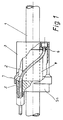
- 2 denotes a traction means, which is attached to a handle 3 rotatable relative to the bicycle handlebar 1.
- the traction means 2 is steered like a helix around a sleeve 4 encasing the bicycle handlebar 1 and guided through a longitudinal guide 5 which is fastened to an annular body 5a which in turn is fixed to the bicycle handlebar 1.
- the attachment point 6 of the traction device 2 on the handle 3 is guided in a circular path around the handlebar 1 and the traction device 2 is thereby moved in its longitudinal guide 5.
- the distance between the attachment point 6 and outlet opening 7 along the axis of rotation is preferably 50 mm.
- the diameter of the sleeve 4 or of the bicycle handlebar 1 is also important for converting the rotary movement into a pull-push movement on the pulling means 2.
- the sleeve preferably has a diameter of 25 mm.
- the direction of the outlet opening 7 is chosen so that it corresponds to the direction of the traction means 2, which it assumes directly outside the longitudinal guide when the handle 3 is in a central position is rotated. In this way, a slight deflection of the traction device is achieved in the entire turning range.
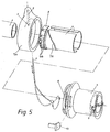
- a further influence on the implementation of the rotary movement in a longitudinal movement is exerted by the position of the traction means 2 between the outlet opening 7 from the longitudinal guide 5 and the attachment point 6 on the handle 3 being inevitably influenced by mechanical elements to which the traction means at least partially abuts .
- elements can be used that rotate with the handle 3 as well as those that are stationary with respect to the handlebar 1.
- Fig. 5 such an element is shown on the sleeve 4 and designated by the reference numeral 7a. In this case, the sleeve 4 is fixed against rotation on the annular body 5a.
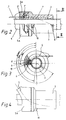
- the rotary handle 3 is fixed in the respective position by a grid for a gear shift stage.
- a detent segment 9 is provided (FIGS. 3 and 5), which is fixed on the annular body 5a.
- the holding force of the catch and the actuating force required to overcome the catch can be adjusted by the catch spring 8 being designed as a curved leaf spring and an adjustable abutment 10 restricting the area in which the leaf spring can bend freely (FIGS. 3 and 5).
- the detent spring 8 is fixed in the direction of rotation on the handle 3 and arranged so that the abutment 10, which is also guided in the handle 3, is easily accessible for actuation.
- the abutment can also be attached to a ring and mounted on the handle 3.
- the ring can have small recesses on its outer surface, through which it can be easily adjusted.
- the locking surfaces 9a of the grid are arranged on the easily replaceable grid segment 9, so that different grids for different gear shifts can be installed by simply exchanging this component.
- the same injection molded parts can be used for rotary handles for the front derailleur of the circuit and for those for the rear derailleur of the circuit except for the locking segment 9 with the locking surfaces.
Landscapes
- Engineering & Computer Science (AREA)
- Mechanical Engineering (AREA)
- Chemical & Material Sciences (AREA)
- Theoretical Computer Science (AREA)
- Combustion & Propulsion (AREA)
- Transportation (AREA)
- General Engineering & Computer Science (AREA)
- General Physics & Mathematics (AREA)
- Physics & Mathematics (AREA)
- Human Computer Interaction (AREA)
- Steering Devices For Bicycles And Motorcycles (AREA)
- Mechanical Control Devices (AREA)
- Flexible Shafts (AREA)
- Gear-Shifting Mechanisms (AREA)
Applications Claiming Priority (2)
| Application Number | Priority Date | Filing Date | Title |
|---|---|---|---|
| DE4420273A DE4420273A1 (de) | 1994-06-10 | 1994-06-10 | Drehgriff zur Betätigung von Fahrradgangschaltungen |
| DE4420273 | 1994-06-10 |
Publications (4)
| Publication Number | Publication Date |
|---|---|
| EP0686552A2 true EP0686552A2 (fr) | 1995-12-13 |
| EP0686552A3 EP0686552A3 (fr) | 1996-01-17 |
| EP0686552B1 EP0686552B1 (fr) | 1999-10-27 |
| EP0686552B2 EP0686552B2 (fr) | 2004-03-24 |
Family
ID=6520248
Family Applications (1)
| Application Number | Title | Priority Date | Filing Date |
|---|---|---|---|
| EP95107647A Expired - Lifetime EP0686552B2 (fr) | 1994-06-10 | 1995-05-19 | Poignée tournante pour le changement de vitesse de bicyclette |
Country Status (6)
| Country | Link |
|---|---|
| US (1) | US5666858A (fr) |
| EP (1) | EP0686552B2 (fr) |
| AT (1) | ATE186030T1 (fr) |
| CA (1) | CA2151298A1 (fr) |
| DE (2) | DE4420273A1 (fr) |
| TW (1) | TW340824B (fr) |
Cited By (3)
| Publication number | Priority date | Publication date | Assignee | Title |
|---|---|---|---|---|
| EP0759393A4 (fr) * | 1995-03-13 | 1998-12-02 | Sakae Co Ltd | Changement de vitesses pour bicyclette et commande du changement de vitesse |
| DE10111297A1 (de) * | 2001-03-09 | 2002-09-12 | Helmig Hans Gmbh | Kettengangschaltung für Fahrräder |
| EP1273507A3 (fr) * | 2001-07-02 | 2004-06-23 | SRAM Deutschland GmbH | Poignée tournante pour un organe de commande de bicyclette |
Families Citing this family (9)
| Publication number | Priority date | Publication date | Assignee | Title |
|---|---|---|---|---|
| AT406365B (de) * | 1997-02-21 | 2000-04-25 | Josef Prajczer | Fahrradgangschaltung |
| DE19753901A1 (de) * | 1997-12-05 | 1999-06-10 | Sram De Gmbh | Schalter für ein Fahrradgetriebe |
| US6041895A (en) * | 1998-04-30 | 2000-03-28 | Mao; Chen Shou | Handlebar brake assembly for bicycles |
| US6296072B1 (en) | 1999-01-20 | 2001-10-02 | Opti-Bike Llc | Electric bicycle and methods |
| US6389925B1 (en) | 1999-02-16 | 2002-05-21 | Shimano Inc. | Shift operating device |
| DE10043612A1 (de) * | 2000-09-05 | 2002-03-14 | Sram De Gmbh | Schalter für ein Fahrrad |
| US7204169B2 (en) * | 2003-04-10 | 2007-04-17 | Ross Mitchell | Gear shifting mechanism |
| US7665383B2 (en) * | 2006-01-31 | 2010-02-23 | Shimano Inc. | Bicycle shift control device |
| US9511815B2 (en) * | 2013-06-28 | 2016-12-06 | Shimano Inc. | Bicycle operating device mounting assembly |
Citations (2)
| Publication number | Priority date | Publication date | Assignee | Title |
|---|---|---|---|---|
| EP0423799A2 (fr) | 1989-10-19 | 1991-04-24 | Toyota Jidosha Kabushiki Kaisha | Dispositif de commande d'une transmission semi-automatique de véhicule incluant des moyens pour empêcher un débrayage complet d'un embrayage automatique pour empêcher le moteur de passer en survitesse |
| US5102372A (en) | 1991-03-20 | 1992-04-07 | Sram Corporation | Bicycle derailleur cable actuating system |
Family Cites Families (16)
| Publication number | Priority date | Publication date | Assignee | Title |
|---|---|---|---|---|
| US635084A (en) * | 1897-11-15 | 1899-10-17 | Abby D Gardner | Grip for bicycles. |
| DE540737C (de) * | 1929-03-16 | 1931-12-30 | Willy Emmer | Lenkstangendrehgriff fuer Motorraeder |
| GB349765A (en) * | 1930-05-21 | 1931-06-04 | Frederick John Robinson | Twist-grip controls for cycle handlebars and the like |
| FR829283A (fr) † | 1936-11-14 | 1938-06-17 | Système de poignée tournante pour la commande d'organes sur motocyclettes et bicyclettes | |
| US2874587A (en) * | 1956-04-09 | 1959-02-24 | Gen Motors Corp | Hand control mechanism for vehicles |
| FR1499803A (fr) † | 1966-11-16 | 1967-10-27 | Véhicule à dérailleur tel que bicyclette | |
| FR1538932A (fr) * | 1967-10-03 | 1968-09-06 | Dispositif de commande notamment du changement de vitesses d'un dérailleur | |
| DE3036111A1 (de) † | 1980-09-25 | 1982-05-06 | Fichtel & Sachs Ag, 8720 Schweinfurt | Kettenschaltung |
| FR2508196A1 (fr) † | 1981-06-17 | 1982-12-24 | Huret & Fils | Mecanisme de guidage et d'actionnement, notamment pour derailleur de bicyclette |
| CH667244A5 (en) * | 1985-08-29 | 1988-09-30 | Pefag Ag | Twist-grip gearchange for bicycle - has clamp for Bowden cable and ratchet location of gears |
| JPS63119196U (fr) * | 1987-01-28 | 1988-08-02 | ||
| JPS63129692U (fr) * | 1987-02-18 | 1988-08-24 | ||
| US5134897A (en) * | 1989-10-20 | 1992-08-04 | Campagnolo S.R.L. | Twist-grip device for operating the gears of a bicycle |
| FR2673594A1 (fr) * | 1991-03-08 | 1992-09-11 | Simplex Sa | Dispositif de freinage pour bicyclettes ou vehicules similaires. |
| JPH0820378A (ja) * | 1991-11-11 | 1996-01-23 | Mori San Tour:Kk | 自転車用変速機構およびこれを用いた変速方法 |
| US5241877A (en) * | 1992-12-04 | 1993-09-07 | Chen Chun Hsung | Gear selector |
-
1994
- 1994-06-10 DE DE4420273A patent/DE4420273A1/de not_active Withdrawn
-
1995
- 1995-05-19 DE DE59507120T patent/DE59507120D1/de not_active Expired - Fee Related
- 1995-05-19 EP EP95107647A patent/EP0686552B2/fr not_active Expired - Lifetime
- 1995-05-19 AT AT95107647T patent/ATE186030T1/de not_active IP Right Cessation
- 1995-05-30 TW TW084105436A patent/TW340824B/zh not_active IP Right Cessation
- 1995-06-02 US US08/460,726 patent/US5666858A/en not_active Expired - Lifetime
- 1995-06-08 CA CA002151298A patent/CA2151298A1/fr not_active Abandoned
Patent Citations (3)
| Publication number | Priority date | Publication date | Assignee | Title |
|---|---|---|---|---|
| EP0423799A2 (fr) | 1989-10-19 | 1991-04-24 | Toyota Jidosha Kabushiki Kaisha | Dispositif de commande d'une transmission semi-automatique de véhicule incluant des moyens pour empêcher un débrayage complet d'un embrayage automatique pour empêcher le moteur de passer en survitesse |
| US5102372A (en) | 1991-03-20 | 1992-04-07 | Sram Corporation | Bicycle derailleur cable actuating system |
| EP0575560A1 (fr) | 1991-03-20 | 1993-12-29 | Sram Corp | Procede et dispositif de changement de vitesse s'utilisant sur un velo. |
Cited By (3)
| Publication number | Priority date | Publication date | Assignee | Title |
|---|---|---|---|---|
| EP0759393A4 (fr) * | 1995-03-13 | 1998-12-02 | Sakae Co Ltd | Changement de vitesses pour bicyclette et commande du changement de vitesse |
| DE10111297A1 (de) * | 2001-03-09 | 2002-09-12 | Helmig Hans Gmbh | Kettengangschaltung für Fahrräder |
| EP1273507A3 (fr) * | 2001-07-02 | 2004-06-23 | SRAM Deutschland GmbH | Poignée tournante pour un organe de commande de bicyclette |
Also Published As
| Publication number | Publication date |
|---|---|
| EP0686552A3 (fr) | 1996-01-17 |
| TW340824B (en) | 1998-09-21 |
| CA2151298A1 (fr) | 1995-12-11 |
| DE4420273A1 (de) | 1995-12-14 |
| EP0686552B1 (fr) | 1999-10-27 |
| DE59507120D1 (de) | 1999-12-02 |
| US5666858A (en) | 1997-09-16 |
| EP0686552B2 (fr) | 2004-03-24 |
| ATE186030T1 (de) | 1999-11-15 |
Similar Documents
| Publication | Publication Date | Title |
|---|---|---|
| DE69510574T2 (de) | Fahrrad-Gangschaltungseinrichtung | |
| DE69203639T2 (de) | Geschwindigkeitssteuergerät für ein Fahrrad. | |
| DE69202179T2 (de) | Brems- und Gangwechselsteuereinrichtung für ein Fahrrad. | |
| DE69130806T2 (de) | Fahrrad-Geschwindigkeitssteuergerät mit Steuerdraht | |
| DE69700390T2 (de) | Fahrrad-Gangschaltungshebel | |
| DE69116516T2 (de) | Fahrradgeschwindigkeitssteuergerät | |
| DE69500508T2 (de) | Rastfeder für Drehhandgriff-Betätigungseinrichtung | |
| DE69014159T2 (de) | Schaltvorrichtung für Fahrradgangschaltung. | |
| DE68920008T2 (de) | Fahrradsteuerungsvorrichtung. | |
| DE69004614T2 (de) | Gangschaltung für ein Fahrrad. | |
| DE2817627C2 (de) | Betätigungseinrichtung für eine Gangschaltung | |
| DE3404800C2 (fr) | ||
| DE3046976A1 (de) | Drosseleinstellvorrichtung | |
| EP0686552A2 (fr) | Poignée tournante pour le changement de vitesse de bicyclette | |
| EP0673825A1 (fr) | Appareil de direction réglable | |
| DE19758288B4 (de) | Verfahren und Vorrichtung zur drehrichtungsgekoppelten Rückstellung eines Schalters | |
| EP0732893B1 (fr) | Instrument chirurgical tubulaire | |
| DE3821792A1 (de) | Hinterrad-kettenumwerfer fuer eine fahrrad-kettenschaltung | |
| DE19614832C1 (de) | Säge für chirurgische Zwecke | |
| EP0508436B1 (fr) | Dispositif de blocage rapide pour une bicyclette | |
| EP0475017A2 (fr) | Dispositif de réglage pour commande par câble | |
| DE19645078A1 (de) | Betätigungsvorrichtung für eine Fahrrad-Kettenschaltung mit einem an der Fahrradlenkstange drehbar angebrachten Betätigungselement | |
| DE10358438A1 (de) | Schaltermechanismus für Fahrradgetriebe | |
| DE4125895C2 (de) | Köderwurfhaspel | |
| DE2723869C2 (de) | Fahrrad-Nabenschaltung |
Legal Events
| Date | Code | Title | Description |
|---|---|---|---|
| PUAI | Public reference made under article 153(3) epc to a published international application that has entered the european phase |
Free format text: ORIGINAL CODE: 0009012 |
|
| PUAL | Search report despatched |
Free format text: ORIGINAL CODE: 0009013 |
|
| AK | Designated contracting states |
Kind code of ref document: A2 Designated state(s): AT BE CH DE DK ES FR GB IT LI NL PT |
|
| AK | Designated contracting states |
Kind code of ref document: A3 Designated state(s): AT BE CH DE DK ES FR GB IT LI NL PT |
|
| 17P | Request for examination filed |
Effective date: 19960507 |
|
| 17Q | First examination report despatched |
Effective date: 19970512 |
|
| GRAG | Despatch of communication of intention to grant |
Free format text: ORIGINAL CODE: EPIDOS AGRA |
|
| GRAG | Despatch of communication of intention to grant |
Free format text: ORIGINAL CODE: EPIDOS AGRA |
|
| GRAG | Despatch of communication of intention to grant |
Free format text: ORIGINAL CODE: EPIDOS AGRA |
|
| GRAH | Despatch of communication of intention to grant a patent |
Free format text: ORIGINAL CODE: EPIDOS IGRA |
|
| GRAH | Despatch of communication of intention to grant a patent |
Free format text: ORIGINAL CODE: EPIDOS IGRA |
|
| GRAA | (expected) grant |
Free format text: ORIGINAL CODE: 0009210 |
|
| AK | Designated contracting states |
Kind code of ref document: B1 Designated state(s): AT BE CH DE DK ES FR GB IT LI NL PT |
|
| PG25 | Lapsed in a contracting state [announced via postgrant information from national office to epo] |
Ref country code: NL Free format text: LAPSE BECAUSE OF FAILURE TO SUBMIT A TRANSLATION OF THE DESCRIPTION OR TO PAY THE FEE WITHIN THE PRESCRIBED TIME-LIMIT Effective date: 19991027 Ref country code: GB Free format text: LAPSE BECAUSE OF FAILURE TO SUBMIT A TRANSLATION OF THE DESCRIPTION OR TO PAY THE FEE WITHIN THE PRESCRIBED TIME-LIMIT Effective date: 19991027 Ref country code: FR Free format text: LAPSE BECAUSE OF FAILURE TO SUBMIT A TRANSLATION OF THE DESCRIPTION OR TO PAY THE FEE WITHIN THE PRESCRIBED TIME-LIMIT Effective date: 19991027 Ref country code: ES Free format text: THE PATENT HAS BEEN ANNULLED BY A DECISION OF A NATIONAL AUTHORITY Effective date: 19991027 |
|
| REF | Corresponds to: |
Ref document number: 186030 Country of ref document: AT Date of ref document: 19991115 Kind code of ref document: T |
|
| REG | Reference to a national code |
Ref country code: CH Ref legal event code: EP |
|
| REF | Corresponds to: |
Ref document number: 59507120 Country of ref document: DE Date of ref document: 19991202 |
|
| ITF | It: translation for a ep patent filed | ||
| ET | Fr: translation filed | ||
| PG25 | Lapsed in a contracting state [announced via postgrant information from national office to epo] |
Ref country code: PT Free format text: LAPSE BECAUSE OF FAILURE TO SUBMIT A TRANSLATION OF THE DESCRIPTION OR TO PAY THE FEE WITHIN THE PRESCRIBED TIME-LIMIT Effective date: 20000127 Ref country code: DK Free format text: LAPSE BECAUSE OF FAILURE TO SUBMIT A TRANSLATION OF THE DESCRIPTION OR TO PAY THE FEE WITHIN THE PRESCRIBED TIME-LIMIT Effective date: 20000127 |
|
| REG | Reference to a national code |
Ref country code: CH Ref legal event code: NV Representative=s name: R. A. EGLI & CO. PATENTANWAELTE |
|
| GBV | Gb: ep patent (uk) treated as always having been void in accordance with gb section 77(7)/1977 [no translation filed] |
Effective date: 19991027 |
|
| PLBI | Opposition filed |
Free format text: ORIGINAL CODE: 0009260 |
|
| PLBF | Reply of patent proprietor to notice(s) of opposition |
Free format text: ORIGINAL CODE: EPIDOS OBSO |
|
| 26 | Opposition filed |
Opponent name: SRAM DEUTSCHLAND GMBH Effective date: 20000722 |
|
| NLR1 | Nl: opposition has been filed with the epo |
Opponent name: SRAM DEUTSCHLAND GMBH |
|
| PLBF | Reply of patent proprietor to notice(s) of opposition |
Free format text: ORIGINAL CODE: EPIDOS OBSO |
|
| PGFP | Annual fee paid to national office [announced via postgrant information from national office to epo] |
Ref country code: AT Payment date: 20010522 Year of fee payment: 7 |
|
| PGFP | Annual fee paid to national office [announced via postgrant information from national office to epo] |
Ref country code: BE Payment date: 20010530 Year of fee payment: 7 |
|
| PGFP | Annual fee paid to national office [announced via postgrant information from national office to epo] |
Ref country code: CH Payment date: 20010829 Year of fee payment: 7 |
|
| RAP2 | Party data changed (patent owner data changed or rights of a patent transferred) |
Owner name: SUNRACE STURMEY-ARCHER INC. |
|
| NLT2 | Nl: modifications (of names), taken from the european patent patent bulletin |
Owner name: SUNRACE STURMEY-ARCHER INC. |
|
| PG25 | Lapsed in a contracting state [announced via postgrant information from national office to epo] |
Ref country code: AT Free format text: LAPSE BECAUSE OF NON-PAYMENT OF DUE FEES Effective date: 20020519 |
|
| PG25 | Lapsed in a contracting state [announced via postgrant information from national office to epo] |
Ref country code: LI Free format text: LAPSE BECAUSE OF NON-PAYMENT OF DUE FEES Effective date: 20020531 Ref country code: CH Free format text: LAPSE BECAUSE OF NON-PAYMENT OF DUE FEES Effective date: 20020531 Ref country code: BE Free format text: LAPSE BECAUSE OF NON-PAYMENT OF DUE FEES Effective date: 20020531 |
|
| REG | Reference to a national code |
Ref country code: CH Ref legal event code: PL |
|
| PGFP | Annual fee paid to national office [announced via postgrant information from national office to epo] |
Ref country code: FR Payment date: 20030528 Year of fee payment: 9 |
|
| PGFP | Annual fee paid to national office [announced via postgrant information from national office to epo] |
Ref country code: NL Payment date: 20030530 Year of fee payment: 9 |
|
| PUAH | Patent maintained in amended form |
Free format text: ORIGINAL CODE: 0009272 |
|
| STAA | Information on the status of an ep patent application or granted ep patent |
Free format text: STATUS: PATENT MAINTAINED AS AMENDED |
|
| 27A | Patent maintained in amended form |
Effective date: 20040324 |
|
| AK | Designated contracting states |
Kind code of ref document: B2 Designated state(s): AT BE CH DE DK ES FR GB IT LI NL PT |
|
| NLR2 | Nl: decision of opposition |
Effective date: 20040324 |
|
| NLV1 | Nl: lapsed or annulled due to failure to fulfill the requirements of art. 29p and 29m of the patents act | ||
| EN | Fr: translation not filed | ||
| PG25 | Lapsed in a contracting state [announced via postgrant information from national office to epo] |
Ref country code: IT Free format text: LAPSE BECAUSE OF NON-PAYMENT OF DUE FEES Effective date: 20050519 |
|
| PGFP | Annual fee paid to national office [announced via postgrant information from national office to epo] |
Ref country code: DE Payment date: 20070704 Year of fee payment: 13 |
|
| PG25 | Lapsed in a contracting state [announced via postgrant information from national office to epo] |
Ref country code: DE Free format text: LAPSE BECAUSE OF NON-PAYMENT OF DUE FEES Effective date: 20081202 |