EP0686580B1 - Ensemble cylindrique avec pièces interconnectables - Google Patents
Ensemble cylindrique avec pièces interconnectables Download PDFInfo
- Publication number
- EP0686580B1 EP0686580B1 EP95303761A EP95303761A EP0686580B1 EP 0686580 B1 EP0686580 B1 EP 0686580B1 EP 95303761 A EP95303761 A EP 95303761A EP 95303761 A EP95303761 A EP 95303761A EP 0686580 B1 EP0686580 B1 EP 0686580B1
- Authority
- EP
- European Patent Office
- Prior art keywords
- projection
- components
- assembly
- movement
- engagement
- Prior art date
- Legal status (The legal status is an assumption and is not a legal conclusion. Google has not performed a legal analysis and makes no representation as to the accuracy of the status listed.)
- Expired - Lifetime
Links
Images



Classifications
-
- B—PERFORMING OPERATIONS; TRANSPORTING
- B65—CONVEYING; PACKING; STORING; HANDLING THIN OR FILAMENTARY MATERIAL
- B65F—GATHERING OR REMOVAL OF DOMESTIC OR LIKE REFUSE
- B65F1/00—Refuse receptacles; Accessories therefor
- B65F1/14—Other constructional features; Accessories
-
- F—MECHANICAL ENGINEERING; LIGHTING; HEATING; WEAPONS; BLASTING
- F16—ENGINEERING ELEMENTS AND UNITS; GENERAL MEASURES FOR PRODUCING AND MAINTAINING EFFECTIVE FUNCTIONING OF MACHINES OR INSTALLATIONS; THERMAL INSULATION IN GENERAL
- F16B—DEVICES FOR FASTENING OR SECURING CONSTRUCTIONAL ELEMENTS OR MACHINE PARTS TOGETHER, e.g. NAILS, BOLTS, CIRCLIPS, CLAMPS, CLIPS OR WEDGES; JOINTS OR JOINTING
- F16B7/00—Connections of rods or tubes, e.g. of non-circular section, mutually, including resilient connections
- F16B7/20—Connections of rods or tubes, e.g. of non-circular section, mutually, including resilient connections using bayonet connections
-
- B—PERFORMING OPERATIONS; TRANSPORTING
- B65—CONVEYING; PACKING; STORING; HANDLING THIN OR FILAMENTARY MATERIAL
- B65F—GATHERING OR REMOVAL OF DOMESTIC OR LIKE REFUSE
- B65F2230/00—Shapes of refuse receptacles
- B65F2230/15—Sleeve having a disconnectable bottom
Definitions
- This invention relates to an assembly of two interfitting generally cylindrical components intended for use, for example, as a litter bin.
- litter bins prefferably be of hollow, generally cylindrical construction with a cylindrical base adapted to be anchored to the ground and a cylindrical body, with one or more openings for litter at the top thereof, arranged to fit into or over the base.
- the upper and lower parts of the litter bin are interlocked in the engaged position in order to prevent unauthorised removal of the upper part of the bin. It is nevertheless desirable that the upper part of the bin be easily removable from the base by service personnel in order to permit access to an internal liner containing the litter.
- US-A-3824815 describes locking apparatus designed to prevent unauthorised unlocking movement between two cylindrical members.
- a first member has a labyrinth relief formation defined on its cylindrical surface and the second member has a locking pawl designed to engage with the labyrinth.
- Unlocking of the members requires a known combination of rotational and axial movement between the members so as to release the pair from the labyrinth.
- an assembly comprising two interfitting generally cylindrical components having sufficient clearance between their mating surfaces to permit relative rotation, at least one retractable locking projection provided on one of said surfaces and biased into a projecting position in which it interlocks with the other of said surfaces, and locking formations on said other surface including at least one corresponding labyrinth of barriers to circumferential and axial movement through which labyrinth(s) said projection(s) may be manoeuvred by a known sequence of axial and rotational relative movements of said components for disengagement thereof, the arrangement of the projection(s) and the locking formations being such that said axial disengaging movement cannot cause retraction of the projection(s) but axial movement in the reverse direction results in temporary deflection of the projection(s) into the retracted position by the locking formations thereby permitting re-engagement of the components to be accomplished by relative axial movement alone, characterised in that the or each projection has a contact surface inclined in the direction of engagement movement of the locking formations so as to enable the locking formations to
- the or each projection is preferably integrally moulded in plastics material.
- Adjacent ends of said portions preferably have interlocking formations to resist reverse deflection of the projection.
- the labyrinth preferably includes a circumferential barrier which is only avoidable by axial movement in the direction of re-engagement.
- the assembly preferably includes a plurality of projections and corresponding labyrinths are unevenly spaced circumferentially so as to provide a limited number (less than said plurality) of start points for disengagement of said components.
- a litter bin comprising a hollow body made from an assembly as claimed in any one of the preceding claims, the cylinder axis of said components being arranged vertically and one of said components providing a base into or over which the other component fits.
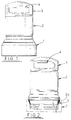
- Fig. 1 shows a litter bin of generally cylindrical shape with an enlarged base portion 1 and an upper body portion 2.
- the upper body portion 2 includes a top 3 with two openings 4 at opposite sides thereof.
- the body portions 1, 2 are of hollow construction and receive a removable litter container (not shown) with an open top immediately below the level of the openings 4.
- the upper body portion 2 is removed from the base 1 in the manner described below.
- the upper and lower portions 1, 2 of the litter bin are rotationally moulded in synthetic plastics material and the base portion 1 is of double skin construction for added strength as shown in Fig. 6.
- the lower end 2a of the upper body portion 2 fits into the base portion 1 as seen in Figs. 2 and 6.
- the interengaging parts of the base and body portions 1 and 2 are of generally cylindrical shape and the mating surfaces have sufficient clearance to admit of easy relative rotation of the base and body portions 1, 2.
- a locking system for interlocking the base and body portions 1, 2 of the litter bin comprises four equally spaced projections 5 mounted on the inner wall of the base portion 1 and corresponding locking formations in the form of labyrinths 7 on the outer surface of the lower end of the body portion 2.
- Each projection 5 comprises an integrally moulded body of synthetic plastics material having an upper portion 5a fixedly secured to the inner wall of the base 1 by fasteners (not shown) extending on lines 5b, 5c through openings in the upper portion 5a of the projection 5.
- the projection 5 also has a lower portion 5d connected to the upper portion 5a by a thin, flexible web 5e providing a hinge enabling resilient retraction of the lower portion 5d in the clockwise direction as seen in Figs. 6 and 6c.
- the lower portion 5d of the projection 5 has a contact surface inclined in the direction of engagement movement of the lower end 2a of the upper body portion 2. Adjacent ends of the upper and lower portions 5a, 5b of the projection 5 are configured as tapered jaws 5f, 5g which are engageable as shown in Fig. 6b to prevent deflection of the portion 5d in the anticlockwise direction indicated by the arrow.
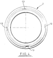
- each labyrinth 7 includes a part-circumferential shoulder 10 providing a further barrier to axial movement of the projections 5 and axially extending abutment surfaces 11, 12 providing barriers to circumferential movement of the projection 5 in opposite directions in its respective labyrinth 7. Adjacent its abutment surface 12 each labyrinth 7 has an exit gate 13 (see also Fig. 4) and adjacent the gate 13 each shoulder 10 has a step 14 providing a further partial barrier to circumferential movement of the respective projection 5.
- the upper body portion 2 of the bin may be rotated clockwise or anticlockwise to bring the entry gates 9 into alignment with the projections 5. This may be done either by aligning discrete marks (not shown) on the base portion 1 and upper body portion 2 or by rotating the upper body portion 2 in either direction whilst simultaneously applying a lifting force until engagement of the projections 5 in the gates 9 is felt. A straight upward lift of the upper body portion 2 then allows the projections 5 to pass through the entry gates 9 into the respective labyrinths 7 where they abut the shoulders 10 to prevent further lifting movement.
- the upper body portion 2 can then be rotated almost a quarter of a turn anticlockwise until the projections 5 encounter the axially extending abutment surfaces 11.
- a small clockwise rotation is possible until the steps 14 adjacent the exit gates 13 are encountered by the projections 5.
- the upper body portion 2 In order to pass the partial barriers to circumferential movement provided by the steps 14 the upper body portion 2 must be lowered slightly back into engagement with the base portion 1 and then rotated clockwise until the axial abutment surfaces 12 are contacted by the projections 5. In this position each projection 5 is aligned with a respect exit gate 13 and the upper body portion may be lifted free.
- Figs. 7 and 8 show the grooves in which the projections 5 locate.
- FIG. 7 is engaged by the projections 5 in the fully inserted position of the upper body portion 2 in the base portion 1 (see inset).
- the upper body portion is capable of rotation through 360° in either direction relative to the base portion 1.
- the locating grooves in the labyrinths 7 are additionally shown cross-hatched and the arrows 16 show possible exit paths for the projections 5.
- the inset of Fig. 8 shows the upper body portion 2 being lifted clear of the base portion 1 with the exit path of the projections indicated by the line with arrow heads at the bottom of the inset.
- the upper body portion 2 may be re-inserted in the base 1 by simply lowering it into the base 1 in any orientation thereof.
- the projections 5 temporarily deflect into their retracted positions under the influence of the protruding shoulder portions at the lower end 2a of the upper body portion 2. As the shoulder 8 passes the free ends of the projections 5 the projections 5 snap back into their fully projecting positions in engagement with the peripheral groove 15.
- the number of projections 5 and corresponding labyrinths 7 may be increased or reduced.
- the projections 5 and labyrinth 7 are evenly spaced thus permitting four equiangularly spaced start positions for the separation movement (i.e. each of the projections 5 can enter any of the labyrinths 7 through the respective entry gate 9).
- the projections 5 and labyrinths 7 are unevenly spaced or sized so as to permit only one or possibly two such start positions.
- the projections 5 may be fabricated in metal, e.g. spring steel.
- the litter bin may be made of alternative materials, e.g.
- the interengaging components are of generally cylindrical form to permit relative rotation of the two parts of the litter bin.
- a simpler or more complex labyrinth structure may be provided although the described design affords a reasonable compromise between complexity deterring unauthorised removal of the upper portion of the litter bin and simplicity permitting easy removal by authorised personnel.
- the arrangement may be reversed with the locking formations provided on the base and the retractable projections mounted on the removable body portion. In this case the projections will be inclined upwardly from their mountings in order to ride over the locking formations during the insertion movement.
Landscapes
- Engineering & Computer Science (AREA)
- General Engineering & Computer Science (AREA)
- Mechanical Engineering (AREA)
- Closures For Containers (AREA)
- Quick-Acting Or Multi-Walled Pipe Joints (AREA)
- Fuses (AREA)
Claims (7)
- Assemblage comprenant deux composants généralement cylindriques (1, 2) s'emboítant l'un dans l'autre, dont l'espace libre ménagé entre leurs surfaces de jointement est suffisant pour permettre leur rotation relative, au moins une saillie de verrouillage rétractable (5) prévue sur une desdites surfaces et mise en état de précontrainte dans une position saillante dans laquelle elle vient se verrouiller de manière réciproque avec l'autre desdites surfaces, ainsi que des structures de verrouillage (8) sur ladite autre surface englobant au moins un labyrinthe correspondant (7) de dispositifs d'arrêt s'opposant au mouvement axial et circonférentiel, la ou lesdites saillies (5) étant à même d'être manoeuvrée(s) à travers le ou lesdits labyrinthes (7) via une séquence connue de mouvements relatifs desdits composants en direction axiale et en rotation pour leur désengrènement, l'arrangement de la ou desdites saillies et des structures de verrouillage (8) étant tel que ledit mouvement de désengrènement axial ne peut provoquer la rétraction de la ou des saillies (5), tandis que le mouvement axial dans la direction opposée donne lieu à un fléchissement temporaire de la ou des saillies (5) dans la position rétractée via les structures de verrouillage (8) pour permettre la mise en oeuvre du réengrènement des composants via uniquement un mouvement axial relatif, caractérisé en ce que la ou chaque saillie (5) possède une surface de contact inclinée dans la direction de mouvement d'engrènement des structures de verrouillage (8) de façon à permettre aux structures de verrouillage d'exercer une force de fléchissement qui augmente progressivement sur la ou les saillies (5) au cours de l'engrènement, la ou chaque saillie (5) possédant une extrémité libre à des fins d'engrènement avec la surface de jointement et étant montée avec un écartement axial par rapport à ladite extrémité libre, la ou chaque saillie (5) possédant des moyens de montage (5b,c) à l'extrémité opposée de ladite extrémité libre et une articulation (5e) au milieu de ses extrémités, l'articulation (5e) reliant l'une à l'autre des portions (5a, 5d) de la ou des saillies (5), mobiles l'une par rapport à l'autre, et possédant des structures de verrouillage réciproque (5f, 5g) qui servent à limiter l'étendue de la position saillante de la ou des saillies (5).
- Assemblage selon la revendication 1, dans lequel la ou chaque saillie est moulée pour faire partie intégrante d'une matière plastique.
- Assemblage selon la revendication 2, dans lequel les structures de verrouillage réciproque (5f, 5g) de la ou des saillies (5) limitent le mouvement latéral relatif des extrémités adjacentes.
- Assemblage selon l'une quelconque des revendications précédentes, dans lequel un certain nombre de saillies (5) et de labyrinthes correspondants (7) sont espacés de manière inéqale en direction circonférentielle de façon à procurer un nombre limité (inférieur audit nombre) de points de départ pour le désengrènement desdits composants.
- Assemblage selon l'une quelconque des revendications précédentes, dans lequel l'articulation 5e ou chaque saillie (5) est décalée en direction axiale et en direction radiale par rapport à une extrémité d'engrènement de la saillie, si bien que le mouvement de séparation des composants donne lieu à un fléchissement inverse limité de la saillie en enqrènement étroit avec la structure de verrouillage coopérante (8).
- Assemblage selon l'une quelconque des revendications précédentes, dans lequel la ou chaque saillie (5) est montée sur une partie renforcée de la surface respective pour empêcher la déformation de ladite surface si l'on tente de séparer les composants par force.
- Poubelle comprenant un corps creux constitué d'un assemblage selon l'une quelconque des revendications précédentes, l'axe cylindrique desdits composants étant arrangé à la verticale et un desdits composants procurant une base dans laquelle ou par-dessus laquelle s'emboíte l'autre composant.
Applications Claiming Priority (2)
| Application Number | Priority Date | Filing Date | Title |
|---|---|---|---|
| GB9411745 | 1994-06-11 | ||
| GB9411745A GB2290019B (en) | 1994-06-11 | 1994-06-11 | A cylindrical assembly for use as a litter bin |
Publications (2)
| Publication Number | Publication Date |
|---|---|
| EP0686580A1 EP0686580A1 (fr) | 1995-12-13 |
| EP0686580B1 true EP0686580B1 (fr) | 2000-03-22 |
Family
ID=10756593
Family Applications (1)
| Application Number | Title | Priority Date | Filing Date |
|---|---|---|---|
| EP95303761A Expired - Lifetime EP0686580B1 (fr) | 1994-06-11 | 1995-06-01 | Ensemble cylindrique avec pièces interconnectables |
Country Status (3)
| Country | Link |
|---|---|
| EP (1) | EP0686580B1 (fr) |
| ES (1) | ES2145215T3 (fr) |
| GB (1) | GB2290019B (fr) |
Families Citing this family (1)
| Publication number | Priority date | Publication date | Assignee | Title |
|---|---|---|---|---|
| US7198098B2 (en) * | 2004-04-22 | 2007-04-03 | Williams John R | Mechanical connection system |
Citations (1)
| Publication number | Priority date | Publication date | Assignee | Title |
|---|---|---|---|---|
| US3824815A (en) * | 1972-10-16 | 1974-07-23 | W Darling | Labyrinth locking apparatus |
Family Cites Families (6)
| Publication number | Priority date | Publication date | Assignee | Title |
|---|---|---|---|---|
| US3703974A (en) * | 1971-03-08 | 1972-11-28 | Leo M Boxer | Safety cap |
| GB2152801B (en) * | 1984-01-13 | 1987-05-20 | Glasdon Ltd | Refuse bins |
| GB8708639D0 (en) * | 1987-04-10 | 1987-05-13 | Hewett M J | Tamper evident & child resistant package |
| GB8807037D0 (en) * | 1988-03-24 | 1988-04-27 | Swintex | Litter bin |
| DK0629169T3 (da) * | 1992-12-11 | 1997-08-25 | Wiva Bv | Dæksel til affaldsbeholder |
| DE9305657U1 (de) * | 1993-04-15 | 1993-06-24 | Georg Menshen GmbH & Co KG, 5950 Finnentrop | Behälter/Verschlußkombination |
-
1994
- 1994-06-11 GB GB9411745A patent/GB2290019B/en not_active Expired - Lifetime
-
1995
- 1995-06-01 ES ES95303761T patent/ES2145215T3/es not_active Expired - Lifetime
- 1995-06-01 EP EP95303761A patent/EP0686580B1/fr not_active Expired - Lifetime
Patent Citations (1)
| Publication number | Priority date | Publication date | Assignee | Title |
|---|---|---|---|---|
| US3824815A (en) * | 1972-10-16 | 1974-07-23 | W Darling | Labyrinth locking apparatus |
Also Published As
| Publication number | Publication date |
|---|---|
| EP0686580A1 (fr) | 1995-12-13 |
| ES2145215T3 (es) | 2000-07-01 |
| GB2290019A (en) | 1995-12-13 |
| GB2290019B (en) | 1998-11-18 |
| GB9411745D0 (en) | 1994-08-03 |
Similar Documents
| Publication | Publication Date | Title |
|---|---|---|
| US5433547A (en) | Shackle with lock pin | |
| DE69813452T2 (de) | Diebstahlsicherungsband für Flaschen | |
| US4991729A (en) | Elder-accessible child-resistant packaging | |
| US7004340B2 (en) | Bottle security device | |
| US4964755A (en) | Manhole cover lock apparatus | |
| US4697444A (en) | Security device for trailer | |
| CN101523005B (zh) | 锁的保护盖 | |
| US5540342A (en) | Tamper resistant lid | |
| US5027630A (en) | Door latch with lock and release for vending machines and the like | |
| US20110011480A1 (en) | Security cap with latch | |
| CA2844233A1 (fr) | Conteneur a dechets a verrou ameliore | |
| KR101942215B1 (ko) | 고정과 개폐가 용이한 맨홀 결합구조체 | |
| WO2014093789A1 (fr) | Dispositif de verrouillage d'attache | |
| EP0686580A1 (fr) | Ensemble cylindrique avec pièces interconnectables | |
| EP0814204B1 (fr) | Ensemble d'avaloir de chaussée et regard de chaussée amélioré pour zônes piétonnes et de trafic | |
| KR100834000B1 (ko) | 맨홀덮개 잠금장치 | |
| EP0227447A2 (fr) | Borne de stationnement | |
| CA2361169C (fr) | Serrure de porte de semi-remorque | |
| JPS60197584A (ja) | 重力作動グリツパ | |
| DE202005009037U1 (de) | Verschluss für eine Ladeluke in einer Seitenwand eines Transportbehälters | |
| EP2508679B1 (fr) | Couvercle pour un réragrd de chaussée | |
| DE2348465A1 (de) | Verriegelungsverschluss fuer einen schallplattenpaket-speicherbehaelter | |
| DE4308861A1 (de) | Stapelbarer Behälter mit Deckel | |
| HK132797A (en) | Lockable slider for a slide fastener | |
| CN103803304A (zh) | 一种传输的方法及装置 |
Legal Events
| Date | Code | Title | Description |
|---|---|---|---|
| PUAI | Public reference made under article 153(3) epc to a published international application that has entered the european phase |
Free format text: ORIGINAL CODE: 0009012 |
|
| AK | Designated contracting states |
Kind code of ref document: A1 Designated state(s): ES FR |
|
| 17P | Request for examination filed |
Effective date: 19960613 |
|
| 17Q | First examination report despatched |
Effective date: 19971022 |
|
| GRAG | Despatch of communication of intention to grant |
Free format text: ORIGINAL CODE: EPIDOS AGRA |
|
| GRAG | Despatch of communication of intention to grant |
Free format text: ORIGINAL CODE: EPIDOS AGRA |
|
| GRAH | Despatch of communication of intention to grant a patent |
Free format text: ORIGINAL CODE: EPIDOS IGRA |
|
| GRAH | Despatch of communication of intention to grant a patent |
Free format text: ORIGINAL CODE: EPIDOS IGRA |
|
| GRAA | (expected) grant |
Free format text: ORIGINAL CODE: 0009210 |
|
| AK | Designated contracting states |
Kind code of ref document: B1 Designated state(s): ES FR |
|
| ET | Fr: translation filed | ||
| REG | Reference to a national code |
Ref country code: ES Ref legal event code: FG2A Ref document number: 2145215 Country of ref document: ES Kind code of ref document: T3 |
|
| PLBE | No opposition filed within time limit |
Free format text: ORIGINAL CODE: 0009261 |
|
| STAA | Information on the status of an ep patent application or granted ep patent |
Free format text: STATUS: NO OPPOSITION FILED WITHIN TIME LIMIT |
|
| 26N | No opposition filed | ||
| PGFP | Annual fee paid to national office [announced via postgrant information from national office to epo] |
Ref country code: ES Payment date: 20120726 Year of fee payment: 18 |
|
| REG | Reference to a national code |
Ref country code: ES Ref legal event code: FD2A Effective date: 20140707 |
|
| PG25 | Lapsed in a contracting state [announced via postgrant information from national office to epo] |
Ref country code: ES Free format text: LAPSE BECAUSE OF NON-PAYMENT OF DUE FEES Effective date: 20130602 |
|
| PGFP | Annual fee paid to national office [announced via postgrant information from national office to epo] |
Ref country code: FR Payment date: 20140609 Year of fee payment: 20 |