EP0686588A2 - Vorrichtung zum Handhaben von Material - Google Patents
Vorrichtung zum Handhaben von Material Download PDFInfo
- Publication number
- EP0686588A2 EP0686588A2 EP95303828A EP95303828A EP0686588A2 EP 0686588 A2 EP0686588 A2 EP 0686588A2 EP 95303828 A EP95303828 A EP 95303828A EP 95303828 A EP95303828 A EP 95303828A EP 0686588 A2 EP0686588 A2 EP 0686588A2
- Authority
- EP
- European Patent Office
- Prior art keywords
- outlet
- conduit
- inlet
- container
- valve
- Prior art date
- Legal status (The legal status is an assumption and is not a legal conclusion. Google has not performed a legal analysis and makes no representation as to the accuracy of the status listed.)
- Withdrawn
Links
- 239000000463 material Substances 0.000 title claims abstract description 33
- 239000004677 Nylon Substances 0.000 claims description 6
- 229920001778 nylon Polymers 0.000 claims description 6
- 238000000034 method Methods 0.000 description 3
- 239000002184 metal Substances 0.000 description 2
- 238000004904 shortening Methods 0.000 description 2
- 239000012190 activator Substances 0.000 description 1
- 238000007599 discharging Methods 0.000 description 1
- 230000005484 gravity Effects 0.000 description 1
- 239000004033 plastic Substances 0.000 description 1
- 230000002787 reinforcement Effects 0.000 description 1
- 230000000284 resting effect Effects 0.000 description 1
- 230000000630 rising effect Effects 0.000 description 1
Images


Classifications
-
- B—PERFORMING OPERATIONS; TRANSPORTING
- B65—CONVEYING; PACKING; STORING; HANDLING THIN OR FILAMENTARY MATERIAL
- B65G—TRANSPORT OR STORAGE DEVICES, e.g. CONVEYORS FOR LOADING OR TIPPING, SHOP CONVEYOR SYSTEMS OR PNEUMATIC TUBE CONVEYORS
- B65G69/00—Auxiliary measures taken, or devices used, in connection with loading or unloading
- B65G69/18—Preventing escape of dust
- B65G69/181—Preventing escape of dust by means of sealed systems
- B65G69/183—Preventing escape of dust by means of sealed systems with co-operating closure members on each of the parts of a separable transfer channel
Definitions
- the invention relates to material handling apparatus, particularly to such an apparatus for transferring material from one container to another.
- apparatus for transferring material from one container to another comprising an extensible conduit, means to extend the conduit, and respective means to open and close an inlet and outlet of the conduit, the arrangement being such that in use the conduit is extended for transfer of material, and the inlet and outlet are opened sequentially whereby to pass material to the conduit from the one container and then from the conduit to the another container.
- the means to open and close the inlet and outlet may comprise a respective valve at each of the inlet and outlet. This provides a relatively simple and controllable apparatus.
- the said means may also comprise a control means to maintain the outlet valve at the desired position and to raise the conduit from the outlet valve whereby to open a discharge opening therebetween.
- the control means may comprise a pulley block and an actuator for moving sheaves of the block towards and away from each other for adjusting the position of the conduit outlet and the outlet valve by respective flexible connectors.
- the flexible connectors may lie substantially along the longitudinal axis of the conduit.
- the flexible connector for the conduit outlet may comprise three equiangularly arranged connectors connected between a relatively rigid rim of the outlet and the axial flexible connector.
- the rim may comprise a wire reinforced rim of the conduit.
- the flexible connectors may comprise nylon ropes or strings.
- the flexible connector for the conduit outlet may be trained round a pulley which is adjustable in position whereby effectively to shorten the flexible connector and raise the outlet from the outlet valve.
- the pulley may be connected to a further actuator for positional adjustment.
- the further actuator may comprise a piston and cylinder arrangement.
- the actuator for the pulley block may comprise a bellows means.
- the bellows means may comprise a double bellows.
- the flexible conduit may comprise a reinforced flexible piping.
- a flange means for connection of the inlet with an outlet of the one container.
- the respective inlet and outlet valves may comprise cone valves, which may preferably be non-metallic.
- the inlet cone valve may comprise an actuator to move the valve means for opening and closing the inlet.
- the actuator may comprise a piston and cylinder arrangement.
- the piston and cylinder arrangement may include a vibrator means.
- apparatus as hereinbefore defined, positioned between the outlet of the one container and the inlet of another container.
- the another container may comprise an intermediate bulk container.
- the one container may comprise an intermediate bulk container.
- apparatus as hereinbefore defined in combination with a lifting actuator and hopper inlet whereby to locate an intermediate bulk container outlet.
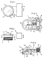
- apparatus for transferring material from one container 2 to another 3 comprising an extensible conduit 4, means 5 to extend the conduit 4, and respective means 6, 7 to open and close an inlet 8 and outlet 9 of the conduit 4, the arrangement being such that in use the conduit 4 is extended for transfer of material, and the inlet 8 and outlet 9 are opened sequentially whereby to pass material 10 to the conduit 4 from the one container 2 and then from the conduit 4 to the another container 3.
- the inlet and outlet closure means 6, 7 in the embodiment each comprise a non-metallic, for example plastic, cone valve which have their apices in line substantially vertically in use and lying substantially along the longitudinal axis of the conduit 4, which comprises a reinforced flexible tube or piping the outlet of which is normally closed by the lower, in use and as shown in the Fig. 7, valve, the upper one 6 in use and as shown in the Fig. 5, normally seating within a mouth 11 defining the inlet 8 of conduit 4.
- the mouth 11 is a flared flange or band which is part of a coated metal, or non-metallic cylinder 12 to which the upper end of the flexible conduit 4 is secured.
- the lower end of the conduit 4 is stiffened by a wire reinforcement rim (not shown).
- a wire reinforcement rim (not shown).
- an actuator 13 carried inside the upper valve 6, in the form of a piston and cylinder arrangement, and there is also a vibrator 14, though this is optional.
- the cylinder 12 has a lateral extension or strut 15 which carries a platform 16 which in turn mounts the means 5 which is a control or actuator means for extending and shortening the conduit 4 and actuating the outlet valve 7.
- the actuator means 5 in the embodiment comprises a movable pulley block system between the sheaves 17 of which is mounted means for moving same in the form of a bellows 18, as shown a double bellows.
- the strut carries 15 a further actuator 19 in the form of a piston and cylinder arrangement, the piston of which is pivoted to a lever arm 20, pivoted at 21 to the strut and which carries at the end opposite the piston a pulley 22, so that the pulley 22 is movable bodily as the piston extends and retracts.
- the movable pulley 22 is part of a pulley system comprising two further pulleys 23, 24 which are fixed.
- One such cord extends from the apex of the outlet cone valve, along the longitudinal axis of the conduit, over a pulley 27 and then round the pulley 24 to the sheaves 17 of the pulley block.
- the other cord 26 is connected at its lower (as viewed) end by three other equiangularly spaced cords 28 to the outlet rim of the conduit 4, and also passes along the longitudinal axis of the conduit 4, over the pulley 27, around the pulley 23, bodily movable pulley 22 and pulley 24 to the sheaves 17 of the pulley block.
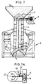
- FIGs. 5 and 5 A the apparatus 1 is clamped by the flange 11 to the outlet of the tablet press 2, and the inlet valve 6 is raised by its piston 13 thereby opening an annular passage through which the material flows to fill the interior of the conduit, which is raised to its upper or shortest extent, with the outlet valve 7 closed by the actuator means 5.
- the two bellows 18 are fully extended to move the sheaves 17 apart and effectively "shorten” the counter nylon ropes 25, 26.
- Another container 3, in the embodiment, is positioned below the outlet 9 of the apparatus 1 (Fig. 5).
- the bellows means 18 is actuated to expand slowly in the direction of arrow 'X', Fig. 8 A , thereby gently raising both the conduit 4 and the lower valve 7 whilst maintaining the open condition of the outlet 9 of the conduit 4 (Fig. 8).
- material 10 continues to flow into the IBC 3, which is thus filled to the desired level.
- the material 10 gently passes out through the annular gap between the outlet 9 and the outlet valve 7 on to the gradually rising top surface of the material 10 in the IBC 3. In this way, the IBC 3 is either completely filled, or filled to a desired level.
- the inlet valve 6 is closed by suitable actuation of its piston/cylinder arrangement 13.
- the flow of material from the one container 2 is ceased.
- the piston/cylinder 19 is activated to retract its piston, so returning the pulley 22 to its initial position so effectively lengthening the nylon connector 26 for the conduit 4, which is thus lowered and repositioned on the outlet valve 7, so closing the annular gap between the outlet 9 and the valve 7 (Fig. 9).
- the bellows 18 continues to expand in the direction of arrow 'Y', Fig. 9 A , so moving the sheaves 18 apart and raising the conduit 4 and outlet valve 7 together until they are fully raised and withdrawn from the IBC (Fig. 5) so that the IBC 3 can be removed for further handling.
- the apparatus 1 is shown used at a discharge station 30 for an IBC which is then the one container 2.
- the IBC is positioned over the apparatus at the discharge station 30, and lowered thereonto so the IBC cone valve 29 is slowly raised to feed material into a discharge hopper and chute 31, which hopper is coated metal or non-metallic.
- the apparatus 1 can be combined with a central lifting actuator and hopper inlet so that a container such as an IBC can be located onto it, full of material in the form say of tablets of friable free flowing product, so that the apparatus can lift a cone valve of the IBC to allow the product to fall a very short distance into the unextended conduit 4, so that thereafter the IBC can be emptied as directed previously into another process vessel or IBC.
- a container such as an IBC can be located onto it, full of material in the form say of tablets of friable free flowing product, so that the apparatus can lift a cone valve of the IBC to allow the product to fall a very short distance into the unextended conduit 4, so that thereafter the IBC can be emptied as directed previously into another process vessel or IBC.
- apparatus 1 can be modified.
- piston and cylinder arrangements 13, 14 have been described, and bellows means 18, as actuators, any suitable activator means can be used, for example electric drive motors to raise and lower the flexible connectors, air motors, or linear motors.
Landscapes
- Engineering & Computer Science (AREA)
- Mechanical Engineering (AREA)
- Filling Or Emptying Of Bunkers, Hoppers, And Tanks (AREA)
- Basic Packing Technique (AREA)
- Supply Of Fluid Materials To The Packaging Location (AREA)
Applications Claiming Priority (2)
| Application Number | Priority Date | Filing Date | Title |
|---|---|---|---|
| GB9411376A GB2290075A (en) | 1994-06-07 | 1994-06-07 | Material handling apparatus |
| GB9411376 | 1994-06-07 |
Publications (2)
| Publication Number | Publication Date |
|---|---|
| EP0686588A2 true EP0686588A2 (de) | 1995-12-13 |
| EP0686588A3 EP0686588A3 (de) | 1997-02-05 |
Family
ID=10756322
Family Applications (1)
| Application Number | Title | Priority Date | Filing Date |
|---|---|---|---|
| EP95303828A Withdrawn EP0686588A3 (de) | 1994-06-07 | 1995-06-05 | Vorrichtung zum Handhaben von Material |
Country Status (5)
| Country | Link |
|---|---|
| US (1) | US5622291A (de) |
| EP (1) | EP0686588A3 (de) |
| JP (1) | JPH07330163A (de) |
| AU (1) | AU2053795A (de) |
| GB (1) | GB2290075A (de) |
Cited By (6)
| Publication number | Priority date | Publication date | Assignee | Title |
|---|---|---|---|---|
| FR2746883A1 (fr) * | 1996-03-26 | 1997-10-03 | American Cyanamid Co | Dispositif de conversion de mouvement lineaire en mouvement rotatif et applicateur de granules correspondant |
| EP1041022A1 (de) * | 1999-03-29 | 2000-10-04 | Zanchetta & C. S.r.l. | Verfahren zum Entladen von Schüttgut aus einem Behälter und Einrichtung dafür |
| GB2368578A (en) * | 2000-10-10 | 2002-05-08 | Ivan Semenenko | Material handling apparatus |
| EP1127816A3 (de) * | 2000-02-25 | 2005-06-15 | ROMACO S.r.l. | Verfahren und Vorrichtung zum Entladen von zerbrechlichen Produkten |
| WO2007011283A1 (en) * | 2005-07-15 | 2007-01-25 | Astrazeneca Ab | A method for transporting a particulate material and a transportation device for a particulate material |
| CN106697571A (zh) * | 2016-08-03 | 2017-05-24 | 上海鸿研物流技术有限公司 | 内衬袋流体排放方法、流体排放系统以及容器 |
Families Citing this family (7)
| Publication number | Priority date | Publication date | Assignee | Title |
|---|---|---|---|---|
| ITBO20030454A1 (it) * | 2003-07-30 | 2005-01-31 | Vima Impianti S R L | Apparato per il trasferimento di materiale incoerente. |
| DE202004003558U1 (de) * | 2004-03-04 | 2004-07-15 | Hexal Ag | Fördervorrichtung mit Einfüllvorrichtung zum entmischungsfreien vertikalen Materialfluss von pulverförmigen Medien |
| US7849892B1 (en) | 2006-09-07 | 2010-12-14 | Remcon Plastics, Inc. | Bulk shipping, storage and discharge box |
| CN108483062A (zh) * | 2018-04-25 | 2018-09-04 | 河南工大设计研究院 | 一种轨道移动式散粮装仓机 |
| MX2021004831A (es) * | 2018-10-29 | 2021-10-13 | Freeze Dried Foods New Zealand Ltd | Liofilizador continuo, tolva y metodo de liofilizacion. |
| CN115781214A (zh) * | 2022-11-15 | 2023-03-14 | 江苏福吉特管业有限公司 | 一种具有自动上下料的自动转位管件装配机 |
| US20250313368A1 (en) * | 2024-04-04 | 2025-10-09 | Dynamic Air Ltda | Retractable tank loading device and its use |
Family Cites Families (11)
| Publication number | Priority date | Publication date | Assignee | Title |
|---|---|---|---|---|
| GB369324A (en) * | 1931-01-28 | 1932-03-24 | Gen Electric Co Ltd | Improvements in or relating to chutes |
| US2223854A (en) * | 1939-05-11 | 1940-12-03 | Milton E Peaster | Antileak nozzle |
| DE894528C (de) * | 1951-04-13 | 1953-10-26 | Ernst Dipl-Ing Jansen | Vorrichtung zum Verladen oder Einspeichern von staubfoermigem Gut |
| US3005473A (en) * | 1959-01-20 | 1961-10-24 | Chapman Chem Co | Liquid filling device |
| US4194615A (en) * | 1975-12-17 | 1980-03-25 | Ab Scaniainventor | Apparatus for unloading loose particulate solid material |
| DE3727561A1 (de) * | 1987-08-19 | 1989-03-02 | Stanelle Karl Heinz | Vorrichtung zum beladen eines silofahrzeuges oder dergleichen mit rieselfaehigem schuettgut |
| DE3838541A1 (de) * | 1988-11-14 | 1990-05-17 | Ladwein Rosemarie | Verfahren zum beschicken eines vorratsbehaelters mit einer trockenmischung und vorrichtung zur durchfuehrung des verfahrens |
| US5016686A (en) * | 1989-10-06 | 1991-05-21 | Atlantic Richfield Company | Method and apparatus for loading particulate materials |
| DE4025341C1 (de) * | 1990-05-15 | 1991-07-25 | O & K Orenstein & Koppel Ag, 1000 Berlin, De | |
| US5082236A (en) * | 1990-07-09 | 1992-01-21 | Custom Metalcraft Inc. | Tablet or capsule drop tube assembly |
| GB2268164B (en) * | 1992-07-01 | 1995-11-29 | Flomat Ltd | Bag emptying arrangement |
-
1994
- 1994-06-07 GB GB9411376A patent/GB2290075A/en not_active Withdrawn
-
1995
- 1995-06-05 EP EP95303828A patent/EP0686588A3/de not_active Withdrawn
- 1995-06-06 US US08/469,910 patent/US5622291A/en not_active Expired - Fee Related
- 1995-06-07 AU AU20537/95A patent/AU2053795A/en not_active Abandoned
- 1995-06-07 JP JP7166943A patent/JPH07330163A/ja active Pending
Non-Patent Citations (1)
| Title |
|---|
| None |
Cited By (9)
| Publication number | Priority date | Publication date | Assignee | Title |
|---|---|---|---|---|
| FR2746883A1 (fr) * | 1996-03-26 | 1997-10-03 | American Cyanamid Co | Dispositif de conversion de mouvement lineaire en mouvement rotatif et applicateur de granules correspondant |
| EP1041022A1 (de) * | 1999-03-29 | 2000-10-04 | Zanchetta & C. S.r.l. | Verfahren zum Entladen von Schüttgut aus einem Behälter und Einrichtung dafür |
| US6293426B1 (en) | 1999-03-29 | 2001-09-25 | Zanchetta & C. S.R.L. | Method for off-loading incoherent material from a container and apparatus for the implementation of the method |
| EP1127816A3 (de) * | 2000-02-25 | 2005-06-15 | ROMACO S.r.l. | Verfahren und Vorrichtung zum Entladen von zerbrechlichen Produkten |
| GB2368578A (en) * | 2000-10-10 | 2002-05-08 | Ivan Semenenko | Material handling apparatus |
| GB2368578B (en) * | 2000-10-10 | 2004-02-11 | Ivan Semenenko | Material handling apparatus |
| WO2007011283A1 (en) * | 2005-07-15 | 2007-01-25 | Astrazeneca Ab | A method for transporting a particulate material and a transportation device for a particulate material |
| CN106697571A (zh) * | 2016-08-03 | 2017-05-24 | 上海鸿研物流技术有限公司 | 内衬袋流体排放方法、流体排放系统以及容器 |
| CN106697571B (zh) * | 2016-08-03 | 2020-08-21 | 上海鸿研物流技术有限公司 | 内衬袋流体排放方法、流体排放系统以及容器 |
Also Published As
| Publication number | Publication date |
|---|---|
| JPH07330163A (ja) | 1995-12-19 |
| GB9411376D0 (en) | 1994-07-27 |
| US5622291A (en) | 1997-04-22 |
| GB2290075A (en) | 1995-12-13 |
| AU2053795A (en) | 1995-12-14 |
| EP0686588A3 (de) | 1997-02-05 |
Similar Documents
| Publication | Publication Date | Title |
|---|---|---|
| US5622291A (en) | Material transfer apparatus with extensible conduit | |
| EP0049992B1 (de) | Vorrichtung zur dosierten Abgabe von fliessfähigem Material aus einem Behälter, wie z.B. einem Silo | |
| EP0705216B1 (de) | Ladevorrichtung für behälter | |
| US7430843B2 (en) | Device and method for filling foil bags with food | |
| EP1950139B1 (de) | Vorrichtung und Verfahren zur Entleerung eines flexiblen Behälters | |
| US6968670B2 (en) | Method of filling a bag and an apparatus for filling a bag | |
| US4944334A (en) | Vibrating hopper and auger feed assembly | |
| US4872493A (en) | Apparatus for filling a lined container | |
| EP0547861B1 (de) | Vorrichtung und System zum kontaminationsfreien Übertragen von fliessfähigem Material zwischen Behältern | |
| US20080142549A1 (en) | Apparatus for the discharge of product from a bulk bag | |
| JPH03501116A (ja) | サイロ車輌等に粉粒物を積載する装置 | |
| WO1990008724A1 (en) | Adjustable discharge valve for container/storage tanks/silos for pulverulent materials | |
| EP4155218A1 (de) | Vorrichtung zur entfernung von luft aus einem beutel mit einem körnigen produkt, maschine und entsprechendes verfahren | |
| JPS62214113A (ja) | 高炉に対する仕込装置 | |
| US20090050446A1 (en) | Method for transporting a particulate material and a transportation device for a particulate material | |
| KR102042987B1 (ko) | 벌크탱크 배출시스템 | |
| EP0043386A1 (de) | Fahrzeug zum Transport pulverförmigen, granulierten oder fragmentierten Materials | |
| US6341715B1 (en) | Valve for the flow control of a fluid comprising solid particles | |
| CN214495000U (zh) | 卸料装置及使用该卸料装置的负压散料输送系统 | |
| WO1995007218A1 (en) | Hopper for dusty materials | |
| JPH0249993B2 (de) | ||
| JPH07108692B2 (ja) | 包装機の充填筒の内部に備えられる積下し用エレベータ | |
| SU971749A1 (ru) | Устройство дл перемещени сыпучих материалов | |
| SU1742138A1 (ru) | Устройство дл загрузки легкоповреждаемых предметов в тару | |
| SU1504179A1 (ru) | Устройство дл перегрузки сыпучих материалов |
Legal Events
| Date | Code | Title | Description |
|---|---|---|---|
| PUAI | Public reference made under article 153(3) epc to a published international application that has entered the european phase |
Free format text: ORIGINAL CODE: 0009012 |
|
| AK | Designated contracting states |
Kind code of ref document: A2 Designated state(s): AT BE CH DE DK ES FR GB GR IE IT LI LU MC NL PT SE |
|
| PUAL | Search report despatched |
Free format text: ORIGINAL CODE: 0009013 |
|
| AK | Designated contracting states |
Kind code of ref document: A3 Designated state(s): AT BE CH DE DK ES FR GB GR IE IT LI LU MC NL PT SE |
|
| 17P | Request for examination filed |
Effective date: 19970721 |
|
| STAA | Information on the status of an ep patent application or granted ep patent |
Free format text: STATUS: THE APPLICATION IS DEEMED TO BE WITHDRAWN |
|
| 18D | Application deemed to be withdrawn |
Effective date: 19990105 |