EP0686592A1 - Dispositif pour la production de produits d'imprimerie - Google Patents
Dispositif pour la production de produits d'imprimerie Download PDFInfo
- Publication number
- EP0686592A1 EP0686592A1 EP95106880A EP95106880A EP0686592A1 EP 0686592 A1 EP0686592 A1 EP 0686592A1 EP 95106880 A EP95106880 A EP 95106880A EP 95106880 A EP95106880 A EP 95106880A EP 0686592 A1 EP0686592 A1 EP 0686592A1
- Authority
- EP
- European Patent Office
- Prior art keywords
- folding
- product
- folded
- products
- folding rollers
- Prior art date
- Legal status (The legal status is an assumption and is not a legal conclusion. Google has not performed a legal analysis and makes no representation as to the accuracy of the status listed.)
- Granted
Links
Images



Classifications
-
- B—PERFORMING OPERATIONS; TRANSPORTING
- B65—CONVEYING; PACKING; STORING; HANDLING THIN OR FILAMENTARY MATERIAL
- B65H—HANDLING THIN OR FILAMENTARY MATERIAL, e.g. SHEETS, WEBS, CABLES
- B65H45/00—Folding thin material
- B65H45/12—Folding articles or webs with application of pressure to define or form crease lines
- B65H45/18—Oscillating or reciprocating blade folders
-
- B—PERFORMING OPERATIONS; TRANSPORTING
- B65—CONVEYING; PACKING; STORING; HANDLING THIN OR FILAMENTARY MATERIAL
- B65H—HANDLING THIN OR FILAMENTARY MATERIAL, e.g. SHEETS, WEBS, CABLES
- B65H29/00—Delivering or advancing articles from machines; Advancing articles to or into piles
- B65H29/38—Delivering or advancing articles from machines; Advancing articles to or into piles by movable piling or advancing arms, frames, plates, or like members with which the articles are maintained in face contact
- B65H29/40—Members rotated about an axis perpendicular to direction of article movement, e.g. star-wheels formed by S-shaped members
-
- B—PERFORMING OPERATIONS; TRANSPORTING
- B65—CONVEYING; PACKING; STORING; HANDLING THIN OR FILAMENTARY MATERIAL
- B65H—HANDLING THIN OR FILAMENTARY MATERIAL, e.g. SHEETS, WEBS, CABLES
- B65H45/00—Folding thin material
- B65H45/12—Folding articles or webs with application of pressure to define or form crease lines
- B65H45/16—Rotary folders
-
- B—PERFORMING OPERATIONS; TRANSPORTING
- B65—CONVEYING; PACKING; STORING; HANDLING THIN OR FILAMENTARY MATERIAL
- B65H—HANDLING THIN OR FILAMENTARY MATERIAL, e.g. SHEETS, WEBS, CABLES
- B65H2301/00—Handling processes for sheets or webs
- B65H2301/40—Type of handling process
- B65H2301/43—Gathering; Associating; Assembling
- B65H2301/434—In channels, e.g. in which the articles are substantially vertical or inclined
- B65H2301/4341—In channels, e.g. in which the articles are substantially vertical or inclined with several channels on a rotary carrier rotating around an axis parallel to the channels
Definitions
- the invention relates to a device for producing printed products consisting of one or more individual products, such as e.g. Newspapers, magazines and the like with a plurality of successive receiving positions arranged between at least one product feed station and at least one product removal station.
- Devices are known from the prior art which can be connected upstream or downstream of devices for compiling or processing printed products and which are only suitable for folding printed products.
- the European parent application EP-A-0 583 602 discloses a folding apparatus to which individual folding sheets or folding sheet packages to be folded can be fed in series, which can then be folded in several folding units at the same time.
- the folding units have transversely movable folding rollers, between which the products to be folded can be moved by means of a folding knife.
- US Pat. No. 3,966,185 also discloses a folding device with two cooperating folding rollers, between which the product to be folded can be moved by means of a folding knife.
- German published application DE-OS 26 09 059 describes a device for folding printed products, in which printed products to be folded can each be folded within a portion of a rotatingly driven cellular wheel.
- An object of the present invention is to design a device of the type mentioned at the outset in such a way that it can be produced economically and can be coupled in a simple manner to devices for compiling or processing printed products, and finally it should also be suitable for processing a continuous product flow .
- each folding device having a pair of folding rollers and a folding sword that moves the product to be folded between the folding rollers.
- all of the receiving positions are each provided with at least one folding device, it is possible to choose the point in time at which the folding processes are triggered in accordance with the particular requirements.
- the folding processes are preferably triggered in the individual pick-up positions when the respective pick-up position passes a certain point on the processing line. In this case, the folding processes are triggered one after the other in successive receiving positions.
- the receiving positions can also be provided with two or more folding devices, so that the products located in the receiving positions can be folded several times accordingly.
- the folding devices it is possible to design the folding devices in such a way that folds running perpendicular to one another can be produced one after the other.
- the individual folding devices can preferably also be designed such that the fold produced in each case of an essentially rectangular printed product comes to lie on the left, right, above or below in accordance with the required further processing of the folded printed products.
- folding devices which, through the folding process, ensure that the printed products are continuously transported in the receiving positions perpendicular to their direction of movement.
- particular care can be taken to ensure that the printed products, for example, continuously run through a substantially spiral processing line, since transport during the folding process in the direction of the longitudinal axis of the essentially spiral processing line is also ensured.
- the folding devices can be provided in the receiving positions of a processing line, which are located between the at least one product feed station and at least one product removal station along the processing line are arranged, with the receiving positions cooperating collecting, inserting, gathering, stitching and / or gluing stations being provided.
- the receiving positions of such a device are loaded with a number of single products along the processing line, as a result of which a printed product consisting of several individual products is put together in the individual receiving positions.
- the compilation is effected by processing stations arranged along the processing line, by means of which the individual products are collected, collected and / or inserted.
- further processing stations for example in the form of gluing, tacking and / or card gluing stations, can be provided along the processing line.
- such a device can be designed such that individual products or products consisting of several individual products can be folded during the passage through the processing line.
- the integration of the folding devices into the processing line significantly increases the possible uses of a device of the type mentioned at the outset, since, without the use of a separate folding device to be provided outside of the processing line, it is also possible to fold the printed products in addition to assembling, stapling and / or gluing the folding devices integrated in the processing line can fold both unfolded and pre-folded printed products consisting of one or more individual products.
- the printed products can already be stapled if necessary.
- this device is also possible to use this device exclusively for folding printed products. This requires an additional increase in the variability of the possible uses of this preferred embodiment of a device according to the invention.
- FIG. 1 shows a substantially horizontal axis 1 rotationally driven cylindrical processing drum 2, which is mounted on a shaft 3 in a frame 4.
- a drive motor 5 is connected to the frame 4 and is coupled to the shaft 3 via a drive belt 6.
- the processing drum 2 which is driven to rotate in the direction of the arrow, is provided with wall elements 7 which extend radially away from its axis 1 and which are arranged on the processing drum 2 in a regularly distributed manner in the circumferential direction.
- a pocket-shaped compartment 8 is formed between each two adjacent wall elements 7 and is used to hold printed products 9.
- the processing drum 2 is coupled to a product feed station, not shown, by means of which individual printed products, each held by a gripper, are fed to the processing drum 2 along a path designated by A.
- the wall elements 7 are each provided with a folding device.
- Each of these folding devices consists of a pair of folding rollers 10, which extend radially with their longitudinal axis from the rotary axis 1 of the processing drum 2 in the plane of the respective wall elements 7.
- the wall elements 7 are interrupted by the same in the area provided for the folding rollers 10. Due to the gap formed between two cooperating folding rollers 10, two mutually adjacent pocket-shaped compartments 8 are connected to one another.
- Each compartment 8 is further provided with a folding blade 11, which is only shown schematically in some compartments 8, and which serves to move a product 9 to be folded with the area to be folded between two cooperating folding rollers 10.
- the folding swords 11 are each acted upon by an actuating mechanism, not shown in FIG. 1, by means of which the front edge of the folding sword can be moved in the direction of the gap formed between two cooperating folding rollers.
- the folding rollers 10 are each acted upon by a rotary drive, also not shown in FIG. 1, which ensures that two cooperating folding rollers rotate in opposite directions about their respective longitudinal axes.
- Each pair of folding rollers 10 has a guide element 12 for the folded products 13 on the side facing away from the respectively associated folding sword 11.
- the guide element 12 extends in each case from the exit side of the gap formed between two folding rollers 10 to an area of the wall element 7 adjacent to the folding rollers 10 on the exit side thereof, offset in the direction of the axis 1 of the processing drum 2.
- a product removal station (not shown in FIG. 1) adjoins the folding section B of the processing drum 2, by means of which the folded products 13 can be conveyed away from the processing drum 2, each of which is held by a gripper (also not shown in FIG. 1).
- the folded products 13 are transported along a path marked C.
- the device shown in Figure 1 operates as follows: While the processing drum 2 is set in rotation via the drive belt 6 and drive motor 5, the individual compartments 8 are fed printed products 9 to be folded.
- the product can be fed in via a clamp conveyor, a conveyor belt or another conveyor device that removes the products 9, for example from a stack.
- a printed product 9 is introduced into each of the successive compartments 8 in the circumferential direction of the processing drum 2.
- the product feed section A is arranged so that the printed products 9 to be folded are stored in the processing direction in front of the folding section B in the compartments 8.
- the printed products 9 to be folded which are thus deposited in the compartments 8, then describe an orbit around the processing drum 2, wherein they are simultaneously transported in the direction of the axis of rotation 1 of the processing drum 2 into the area of the folding section B by means of conveying means (not shown in FIG. 1) , so that the printed products 9 to be folded ultimately describe a substantially spiral orbit along the processing line.
- the printed products 9 to be folded are transported so far into the folding section B that the area of the printed products provided for the folding edge comes to lie in the area of the gap formed between two folding rollers 10.
- the folding blade 11 assigned to the respective gap is then actuated in such a way that the area of the printed product 9 to be folded intended for the folding edge is moved into the gap formed between the respective folding rollers 10.
- the folding rollers 10 which are set in rotation, clamp the printed product 9 to be folded between them and convey them, while simultaneously folding, to the side of the wall element 7 provided with the respective folding rollers 10 facing away from the respectively assigned folding blade 11.
- the folded printed product 13 is deflected and guided by the guide element 12 in such a way that it executes a movement in the direction of the axis of rotation 1 of the processing drum 2, so that the folded printed product 13 continues essentially moved on a continuous, substantially spiral path around the axis of rotation 1 of the processing drum 2.
- the folding devices shown in FIG. 1 cause the folding in such a way that the folding edge comes to lie at the front within the compartments 8 in the transport direction.
- the folded product 13 is then in turn gripped by a conveyor mechanism (not shown in FIG. 1), which continues to provide a conveying process in the direction of the axis of rotation 1 of the processing drum 2, so that the product 13 continues to follow an essentially spiral path even after the folding section B. describes the axis of rotation 1 of the processing drum 2.
- folding device consisting essentially of folding rollers 10, folding blade 11 and guide element 12 each Is arranged within a wall element 7 which defines two adjacent compartments 8 from one another, it is achieved that the product or product 9, 13 is moved during the folding through the section of the respective wall element 7 interrupted by the folding rollers 10, whereby the folded product 13 finally in a compartment 8 comes to rest, which is adjacent to the compartment 8 in the circumferential direction of the processing drum 2, into which the product 9 was introduced before the folding process was carried out along the product feed path A.
- the product removal station like the product feed station, can be designed as a clamp conveyor, as a conveyor belt or the like.
- the transport means which convey the products in the direction of the axis 1 of the processing drum 2, can also serve at the same time to prevent the products from falling out of the compartments 8 in the lower section of the processing drum 2.
- both unfolded and pre-folded products can be processed, whereby the products can consist of one or more individual products.
- FIG. 2 shows a horizontal axis 14 spaced apart from one another, only one of which is shown in FIG. 2, rotating in the direction of the arrows D.
- driven tension member 15 which is designed for example in the form of an endless belt.
- Wall elements 16, which extend substantially perpendicular to the tension element 15, are arranged on the tension element 15 in a regularly distributed manner in the direction of rotation.
- the wall elements 16 have a slight inclination against the direction of rotation D of the tension member.
- a pocket-shaped compartments 17 having a substantially U-shaped cross section are formed between the wall elements 16.
- the wall elements 16 are each interrupted by an arrangement of two folding rollers 18 running perpendicular to the horizontal axis 14, the axes of rotation of which each run parallel to the wall elements, a tangent common to a pair of folding rollers 18 essentially in the plane of the wall elements interrupted by the respective folding rollers 18 16 runs.
- a folding sword 19 is pivotally arranged about a pivot axis 20, which for the sake of clarity in FIG. 2 is only drawn completely in one compartment and schematically indicated in two further compartments.
- the folding blade 19, which cooperates with a pair of folding rollers 18, is attached to the wall element 16 arranged in front of the pair of folding rollers 18 in the direction of transport, the pivot axis 20 of the folding blade 19 extending parallel to the axes of rotation of the folding rollers 18.
- the folding swords 19 are pivotable about their pivot axis 20 in such a way that the respective folding edge 21 of the Folding swords 19 can be moved on the respective feed side of the respective pair of folding rollers 18 in the direction of the gap formed between the folding rollers 18.
- each pair of folding rollers 18 Provided on the exit side of each pair of folding rollers 18 is a dividing wall 22 curved in the direction of the respective exit gap, which divides each compartment 17 into an infeed sector for a first pair of folding rollers 18 and an outfeed sector for a second pair of folding rollers adjacent in the conveying direction of the pulling element 15 18 divided.
- the partition walls 22 extend in an arc from the exit gap of the folding rollers 18 to the region approximately in the middle between two adjacent wall elements 16, where they then run parallel to the wall elements 16.
- a product feed station (not shown in FIG. 2) is provided on one side of the upper run of the pulling member 15 and moves the products 23 to be folded along the product feed path marked E into the respective feed sector of a pocket-shaped compartment 17.
- the product feed section E essentially runs in a plane parallel to the upper run of the pulling member 15.
- a product removal station On the other side of the upper run 15, a product removal station, also not shown in FIG. 2, is provided, by means of which the folded products 24 are removed from the respective conveying sectors of the pocket-shaped compartments 17. The removal takes place along a product removal line F.
- the device shown in FIG. 2 functions as follows:
- the traction element 15 is driven in a rotating manner about the axis 14 and about a further axis, not shown in FIG. 2 and parallel to the axis 14, with products 23 to be folded being fed along the product feed path E at the same time.
- the speed of the product feed station is synchronized with the rotational speed of the pulling element 15, so that a product 23 to be folded is placed in each of the successive compartments 17.
- the product feed station designed for example as a clamp transporter, is arranged relative to the device shown in FIG. 2 in such a way that the feed products 23 are held and transported by the feed device until the products 23 come to lie within the compartments 17 such that the area of the products 23 to be folded is located directly in front of the feed nip of the respective folding rollers 18. In this way it is possible to dispense with a separate transport device provided in the respective compartments 17, which conveys the products 23 along the compartments 17 to the position in which the folding process can be triggered.
- the product to be folded is released by the product feed station.
- the product 23 to be folded is located between the folding rollers 18 causing the folding process to be carried out and the folding edge 21 of a folding sword 19 assigned to these folding rollers 18.
- the respective folding blade 19 is then pivoted about its axis 20, as a result of which the area of the product 23 to be folded is folded by means of the folding edge 21 into the The nip of the folding rollers 18 is pressed, whereupon the rotating folding rollers 18 grip the product 23 to be folded in the area to be folded.
- the product 23 to be folded is then pulled through the gap formed between the folding rollers 18 with a leading folding edge, the folded product 24 on the exit side of the folding rollers 18 being guided through the bent region of the respective partition wall 22 into the respective conveying sector, which is between a wall element 16 and a partition 22 is formed.
- the folded product 24 is conveyed away from the folding rollers 18 along the conveying sector.
- a separate transport device to be provided in the respective conveying sector.
- the folded products 24 are transported away from the product removal station (not shown in FIG. 2) along the product removal line F.
- compartments 17 can each be provided with two or more folding devices so that the individual products can be provided with two or more, in particular differently oriented, folds.
- FIG. 3 shows a processing drum 25 corresponding to a device according to FIG. 1, which is driven to rotate in the direction of the arrow.
- FIG. 3 shows a section through the processing drum 25 in two different planes which are offset along the axis of rotation 26 of the drum 25.
- the first cutting plane shown on the right in FIG. 3, is located in the area of a product feed station 27 designed as a clamp transporter, which holds products to be folded 28 by means of a clamp 29 and moves them into compartments 30 which are between saddle-shaped wall elements that extend radially away from the drum 25 31 are formed.
- a product feed station 27 designed as a clamp transporter, which holds products to be folded 28 by means of a clamp 29 and moves them into compartments 30 which are between saddle-shaped wall elements that extend radially away from the drum 25 31 are formed.
- Each compartment 30 is provided in its region facing the axis of rotation 26 of the processing drum 25 with a pivotable clamp element 32, by means of which the products 28 located in the compartments 30 can be conveyed along the individual compartments 30 transversely to the direction of rotation of the processing drum 25.
- the clamp elements 32 are also suitable for securing the products 28 against falling out of the compartments 30 in the lower region of the processing drum 25.
- the bracket elements 32 only fulfill the holding function described.
- the section plane shown in the left area of FIG. 3 runs offset along the longitudinal axis 26 of the processing drum 25 to the area of the product feed station 27.
- the partition walls 31 are provided with folding devices which, analogous to the representations in FIGS. 1 and 2, essentially consist of a pair of folding rollers 33, a folding sword 35 which can be pivoted about an axis 34 and a guide element 36 for the folded product 37 .
- the folding rollers 33 run essentially in the plane of the wall elements 31 parallel to the axis of rotation 26 of the processing drum 25.
- a fold can be produced with a device shown in FIG. 3 which is perpendicular to one with a 1 foldable device shown in FIG.
- a product removal station 38 which runs essentially tangentially and vertically past the processing drum 25 and which, like the product feed station 27, is designed as a clamp conveyor.
- the device shown in FIG. 3 functions as follows: The products 28 to be folded are introduced into the successive compartments 30 via the product feed station, the transport speed of which is synchronized with the rotational speed of the processing drum 25.
- the products 28 to be folded are gripped by the clamp elements 32, held and possibly conveyed transversely to the direction of rotation of the processing drum 25.
- the products 28 to be folded are positioned relative to the folding devices in such a way that the area to be folded comes to lie relative to the feed area of the folding rollers 33, the products to be folded are released by the clamp elements 32.
- a pivoting movement of the folding blade 35 is then triggered, which presses the area of the products 28 to be folded into the gap formed between the folding rollers 33.
- the fold is always produced at a distance from the end of the product 28 facing the axis of rotation 26 of the processing drum 25, the distance between the end of the compartments 30 facing the axis of rotation 26 and that formed between the folding rollers 33 corresponds to the gap running parallel to the axis of rotation 26.
- the product to be folded is drawn through the gap formed between the folding rollers 33 and then deflected by the guide element 36 in such a way that the folded product 37 with its folded edge is conveyed approximately radially away from the axis of rotation 26 of the processing stream 25.
- the guide element 36 preferably does not run exactly radially to the axis of rotation 26 of the processing drum 25, but rather slightly inclined in the direction of rotation of the processing drum 25.
- the folded product 37 Due to the continued rotation of the processing drum 25 after the folding process, the folded product 37 finally reaches one on the guide element 36 Oblique position that, due to the force of gravity on the guide element 36, it slides essentially radially away from the axis of rotation 26 of the processing drum 25, this sliding process finally being braked by one clamp 39 each of the product removal station 38, since the radially sliding folded product 37 beats against an opened clamp 39 stops, which is moved synchronously with the rotational movement of the processing drum 25.
- the folded product 37 abutting against the clip 39 is gripped by the closing clip 39 on the folded side and conveyed away by the processing drum 25.
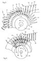
- FIG. 4 shows an alternative embodiment of a folding sector of a processing drum 40 rotating in the direction of the arrow shown in the left area of FIG. 3.
- Each compartment 44 is provided with a pair of folding rollers 46 which are arranged in the wall elements 43 in accordance with FIG. 3.
- a folding blade 47 interacts, which is pivotably mounted about the pivot axis 48 and is connected to a lever element 49.
- the lever element 49 runs over a stationary link 50, which deflects the lever element 49 in such a way that the folding sword 47 connected to it is moved in the direction of the gap formed between two folding rollers 46.
- the product 42 which is pulled through between two folding rollers 46 at the same time, is deflected on the exit side of the folding rollers 46 by a guide element 51 in such a way that its folding edge is moved radially in the direction of the axis of rotation 45 of the processing drum 40.
- the folded product 52 After the folded product 52 has been released by the folding rollers 46, due to its effect of gravity, it slides further radially in the direction of the axis of rotation 45 of the processing drum 40 until it finally strikes the end region of the compartment 44 facing the axis of rotation 45. In this area, the folded product 52 is gripped by a pivotable clamp element 53, the folded product 52 being held by the clamp element 53 on the side provided with the fold.
- the clamp element 53 can serve to secure the folded product 52 against sliding out of the compartment 44, in particular in the lower region of the processing drum 40. Likewise, the clamp element 53 can, if appropriately designed, convey the folded products 52 transversely to the direction of rotation of the processing drum 40.
- both horizontally and vertically running folds can be produced, the folded product being able to be oriented when it is removed from the processing drum in such a way that the last fold produced comes to lie at the top, bottom, left or right.
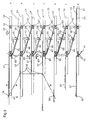
- Fig. 5 shows individual, along a processing line successive, moved in the direction of arrow G and according to the invention provided with folding devices receiving positions that are in different operating states according to their respective position in the processing line.
- FIG. 5 Shown in positions a to g are seven consecutive wall elements 54 which are designed in accordance with FIG. 1 and extend perpendicular to the conveying direction G.
- the illustration of FIG. 5 corresponds essentially to the unwound jacket of a processing drum according to FIG. 1.
- each of the wall elements 54 a pair of folding rollers 55 is integrated, the diameter of which corresponds approximately to the thickness of the wall elements 54.
- a slide 56 is provided on each wall element 54, which can be designed, for example, in accordance with European patent application EP-A-550 828 and is suitable for conveying a product 57 to be folded in the direction of arrow H into the area of the folding rollers 55.
- the slide 56 is movable both in the direction of arrow H and in the opposite direction.
- a folding sword 60 Arranged in each compartment 59 formed between two adjacent wall elements 54 is a folding sword 60 which can be moved along the arrows K and which in its front area has a folded edge 61.
- a deflection roller 62 is integrated in each wall element 54, the axis of rotation of which runs parallel to the axis of rotation of the folding rollers 55.
- Another deflection roller 63 is spaced in the direction of arrow G from the deflection roller 62, the distance between the two deflection rollers 62 and 63 essentially corresponding to the width of a compartment 59.
- a conveyor belt 64 runs over the deflection rollers 62, 63 and over the folding roller 55 facing the deflection roller 62 and is supported on an additional guide roller 65 in the area between the folding roller 55 and the deflection roller 63.
- the conveyor belt 64 is driven either by one of the deflection rollers 62, 63 or by the folding roller 55.
- the drive is preferably carried out via the folding roller 55.
- a support rail 66 extends obliquely from a wall element 54 to a wall element 54 adjacent to it, essentially parallel to the region of the conveyor belt 64 running between the folding roller 55 and the deflection roller 63. In the region of the folding rollers 55, the support rail 66 is angled to an exact To ensure guidance of a folded product 68 on the exit side of the folding rollers 55.
- the device shown in FIG. 5 functions as follows: A product 57 to be folded with its rear end against the slide 56 (position a) is in the direction of Arrow H is conveyed into the area of the folding rollers 55 until its front end strikes the stop 58 (position b). By adjusting the stop 58 in the direction of the double arrow J, the distance between the front edge of the product 57 to be folded and the folding edge to be produced can be set. In this way, the device according to FIG. 5 can be adjusted to different product formats, in particular eccentric folds can also be produced, as are required, for example, for pre-folding products.
- the folding blade 60 is moved in the direction of the gap formed between the folding rollers 55 (position c). As a result, the area to be folded of the product 57 to be folded is pressed into the gap formed between the folding rollers 55 by means of the folding edge 61 of the folding blade 60.
- the product 57 to be folded is drawn with its fold 67 ahead through the gap formed between the folding rollers 55 (position d).
- the product 57 in the folding process is guided through the support rail 66 on the exit side of the gap formed between the folding rollers 55.
- the slide 56 can be moved back to its starting position (position e).
- the slide 56 describes a movement corresponding to the arrow M shown in FIG. 5.
- the folded product released by the folding rollers 55 68 is clamped between the support rail 66 and the revolving conveyor belt 64 and is thus conveyed further in the direction of the wall element 54 adjacent to the folding rollers 55 on its exit side (positions f and g).
- a product 57 to be folded passes from a compartment 59 into an adjacent compartment 59, this folding process being brought about by a folding device which is integrated in a wall element delimiting the two adjacent compartments 59 from one another.
- FIG. 6 shows the flow diagram of a folding process that can be carried out with a device according to FIG. 3.
- the products 69 to be folded are fed in the direction of the arrow to the processing drum 25 rotating about the axis of rotation 26 in the direction of the arrow, whereupon they are conveyed within the compartments perpendicular to the feed direction into the area of the folding devices.
- a product 69 ' is located in the area of the folding devices, the folding process is carried out during the rotation of the processing drum 25, so that finally a folded product 70 is formed, the folding edge of which runs parallel to the axis of rotation 26 of the processing drum 25.
- the folded product 70 is conveyed away from the processing drum 25 in a direction offset parallel to the feed direction.
- FIG. 7 shows a flow diagram of a folding process which can be carried out with a combination of the devices according to FIGS. 1 and 3.
- each compartment of the processing drum 71 is provided with two folding devices which are suitable for producing folds running perpendicular to one another.
- the products 73 to be folded are fed in the direction of the arrow to the processing drum 71 rotating about the axis 72 in the direction of the arrow.
- the product 73 to be folded passes through a folding device according to FIG. 1, whereby a fold 74 running perpendicular to the axis of rotation 72 is produced.
- the product 75 once folded in this way, then passes through a further folding device when the processing drum 71 rotates, which is designed in accordance with FIG. 3. In this way, a further fold 76 is produced, which runs perpendicular to the fold 74.
- the double-folded product 77 is conveyed away from the processing drum 71 in a direction offset parallel to the feed direction.
- FIG. 8 shows the flow diagram of a folding process that can be accomplished with a device according to FIG. 4.
- the product 42 to be folded is fed to the processing drum 40 rotating about the axis 45 already in the area of the folding devices.
- the folding devices each having two folding rollers 46 produce a fold 78 which runs parallel to the axis of rotation 45 of the processing drum 40.
- the fold-in products 79 thus produced come to lie in the compartments 44 with the fold 78 facing the axis of rotation 45 and are conveyed away from the region of the folding devices in the direction of the arrow perpendicular to the feed direction and parallel to the axis of rotation 45 within the compartments 44.
- the area of the compartments 44 in which the fold-in products 79 come to lie after the folding process is radially less far from the axis of rotation 45 of the processing drum 40 than the folding devices.
- a collecting process can additionally take place by means of a collecting station, not shown in FIG. 8.
- the folded products 79 are removed from an area of the processing drum 40 which is offset in the direction of the axis of rotation 45 from the area of the folding devices, and are conveyed away from the processing drum 40 counter to the feed direction.
- FIG. 9 shows a flow diagram of a folding process that can be accomplished with a device according to FIG. 3 or 4.
- the products 80 to be folded are fed to the processing drum 82 rotating about the axis 81 in the direction of the arrow, the feeding already taking place in the sector of the processing drum 82 provided with the folding devices.
- the folded product 83 is conveyed away from the processing drum 82, the infeed and outfeed directions in FIG. 9 being essentially the same and not offset from one another.
- FIG. 10 shows the flow diagram according to FIG. 9 including the implementation of a further folding.
- the once-folded product 83 is conveyed in a compartment parallel to the axis of rotation 84 of the processing drum 85, a further fold being generated during this conveying process, which fold is perpendicular to the one previously produced Fold runs.
- This further fold can be produced, for example, with a device according to FIG. 1. In this way, as with a device according to FIG. 7, a product 86 with two folds running perpendicular to one another can be produced.
- FIG. 11 shows the flow diagram of a folding process carried out according to the invention with a combined insertion process.
- the product 87 to be folded which is already stapled by means of staples 87 ', is divided into a compartment Processing drum or a circulation system inserted until it hits the lower region 88 of the compartment with its lower edge.
- the product 87 is then folded, transported in the longitudinal direction of the compartment and opened, the flower of the folded product 89 coming to rest on the side facing away from the processing drum or the circulation system.
- a printed product 90 is then inserted into the folded product 89 in the direction of the arrow.
- the folded product 89 with the inserted product 90 is conveyed away from the device in the direction of the arrow.
- FIG. 11 shows that, according to the invention, both folding and inserting can be carried out with a single device.
- a device according to the invention can also be coupled to a stitching and / or gluing station.
- FIG. 12 shows a drive diagram for folding rollers of a folding device according to the invention, which is designed in particular in accordance with FIG. 8. This drive scheme can be modified accordingly even with folding rollers oriented parallel to the axis of rotation of the processing drum apply.
- Two cooperating folding rollers 91 are held in a wall element 92 of a processing drum, the axes of rotation 93 of the folding rollers 91 running parallel to the axis of rotation of the processing drum.
- the folding rollers 91 are each fixedly coupled to a gear 94 arranged concentrically with their axes of rotation 93, the two gears 94 meshing with one another.
- the gear 94 of one of the two folding rollers 91 is coupled to an axially offset gear 95, which in turn is in engagement with a gear 96 which is arranged concentrically with the axis of rotation of the processing drum.
- This gear 96 is stationary and consequently does not rotate together with the processing drum.
- the gearwheel 95 rolls on the stationary gearwheel 96 and thus causes the gearwheel 94 coupled to the gearwheel 95 to rotate. Since the two gearwheels 94 mesh with one another, the two folding rollers 91 are rotated in opposite directions.
Landscapes
- Engineering & Computer Science (AREA)
- Mechanical Engineering (AREA)
- Folding Of Thin Sheet-Like Materials, Special Discharging Devices, And Others (AREA)
- Making Paper Articles (AREA)
- Coloring (AREA)
- Printing Methods (AREA)
- Agricultural Chemicals And Associated Chemicals (AREA)
- Threshing Machine Elements (AREA)
Applications Claiming Priority (2)
| Application Number | Priority Date | Filing Date | Title |
|---|---|---|---|
| CH1783/94 | 1994-06-07 | ||
| CH178394 | 1994-06-07 |
Publications (2)
| Publication Number | Publication Date |
|---|---|
| EP0686592A1 true EP0686592A1 (fr) | 1995-12-13 |
| EP0686592B1 EP0686592B1 (fr) | 1999-03-24 |
Family
ID=4218504
Family Applications (1)
| Application Number | Title | Priority Date | Filing Date |
|---|---|---|---|
| EP95106880A Expired - Lifetime EP0686592B1 (fr) | 1994-06-07 | 1995-05-06 | Dispositif pour la production de produits d'imprimerie |
Country Status (9)
| Country | Link |
|---|---|
| US (1) | US5628501A (fr) |
| EP (1) | EP0686592B1 (fr) |
| JP (1) | JPH0859073A (fr) |
| AT (1) | ATE178022T1 (fr) |
| CA (1) | CA2150886A1 (fr) |
| DE (1) | DE59505411D1 (fr) |
| DK (1) | DK0686592T3 (fr) |
| ES (1) | ES2129151T3 (fr) |
| FI (1) | FI952773A7 (fr) |
Cited By (2)
| Publication number | Priority date | Publication date | Assignee | Title |
|---|---|---|---|---|
| WO1998024069A1 (fr) * | 1996-11-28 | 1998-06-04 | Jaime Sallen Rosello | Systeme automatique manipulateur de billets |
| US8378829B2 (en) | 2007-05-29 | 2013-02-19 | Ferag Ag | Method for monitoring and/or controlling a transport device, transport device for carrying out said method and clamp for detachably holding and transporting |
Families Citing this family (4)
| Publication number | Priority date | Publication date | Assignee | Title |
|---|---|---|---|---|
| NL1008726C2 (nl) * | 1998-03-27 | 1999-09-28 | Oce Tech Bv | Vouwinrichting voor het dubbelvouwen van een vel. |
| CA2600698A1 (fr) * | 2005-03-29 | 2006-10-05 | Concepts For Success | Procede de traitement de toile et equipement |
| US9259891B2 (en) | 2013-06-14 | 2016-02-16 | Electronic Imaging Services, Inc. | Pad of labels and labels for use on store shelves in a retail environment |
| US9376286B1 (en) | 2014-09-02 | 2016-06-28 | Electronic Imaging Services, Inc. | Label stacking machine and method |
Citations (3)
| Publication number | Priority date | Publication date | Assignee | Title |
|---|---|---|---|---|
| US3966185A (en) * | 1972-06-19 | 1976-06-29 | Mccain Manufacturing Corporation | Book making |
| DE2609059A1 (de) * | 1975-04-01 | 1976-10-14 | Ferag Ag | Einrichtung zum falten von druckprodukten |
| EP0583602A1 (fr) * | 1992-07-17 | 1994-02-23 | MAN Roland Druckmaschinen AG | Dispositif de pliage |
Family Cites Families (2)
| Publication number | Priority date | Publication date | Assignee | Title |
|---|---|---|---|---|
| US4022456A (en) * | 1975-07-11 | 1977-05-10 | The Procter & Gamble Company | Method and apparatus for folding and cutting an interconnected web of disposable diapers or the like having stretched elastic leg bands secured thereto |
| EP0550828B1 (fr) * | 1992-01-10 | 1995-08-09 | Ferag AG | Procédé et dispositif de traitement de produits imprimés |
-
1995
- 1995-05-06 AT AT95106880T patent/ATE178022T1/de not_active IP Right Cessation
- 1995-05-06 EP EP95106880A patent/EP0686592B1/fr not_active Expired - Lifetime
- 1995-05-06 DE DE59505411T patent/DE59505411D1/de not_active Expired - Lifetime
- 1995-05-06 ES ES95106880T patent/ES2129151T3/es not_active Expired - Lifetime
- 1995-05-06 DK DK95106880T patent/DK0686592T3/da active
- 1995-06-02 CA CA002150886A patent/CA2150886A1/fr not_active Abandoned
- 1995-06-05 JP JP7138049A patent/JPH0859073A/ja active Pending
- 1995-06-06 FI FI952773A patent/FI952773A7/fi unknown
- 1995-06-07 US US08/477,286 patent/US5628501A/en not_active Expired - Fee Related
Patent Citations (3)
| Publication number | Priority date | Publication date | Assignee | Title |
|---|---|---|---|---|
| US3966185A (en) * | 1972-06-19 | 1976-06-29 | Mccain Manufacturing Corporation | Book making |
| DE2609059A1 (de) * | 1975-04-01 | 1976-10-14 | Ferag Ag | Einrichtung zum falten von druckprodukten |
| EP0583602A1 (fr) * | 1992-07-17 | 1994-02-23 | MAN Roland Druckmaschinen AG | Dispositif de pliage |
Cited By (3)
| Publication number | Priority date | Publication date | Assignee | Title |
|---|---|---|---|---|
| WO1998024069A1 (fr) * | 1996-11-28 | 1998-06-04 | Jaime Sallen Rosello | Systeme automatique manipulateur de billets |
| ES2133122A1 (es) * | 1996-11-28 | 1999-08-16 | Sallen Rosello Jaime | Adicion a la patente principal n. p9602515 por: sistema automatico manipulador de billetes. |
| US8378829B2 (en) | 2007-05-29 | 2013-02-19 | Ferag Ag | Method for monitoring and/or controlling a transport device, transport device for carrying out said method and clamp for detachably holding and transporting |
Also Published As
| Publication number | Publication date |
|---|---|
| AU680734B2 (en) | 1997-08-07 |
| AU1791795A (en) | 1995-12-14 |
| FI952773A0 (fi) | 1995-06-06 |
| JPH0859073A (ja) | 1996-03-05 |
| ATE178022T1 (de) | 1999-04-15 |
| EP0686592B1 (fr) | 1999-03-24 |
| CA2150886A1 (fr) | 1995-12-08 |
| DE59505411D1 (de) | 1999-04-29 |
| DK0686592T3 (da) | 1999-05-25 |
| ES2129151T3 (es) | 1999-06-01 |
| US5628501A (en) | 1997-05-13 |
| FI952773L (fi) | 1995-12-08 |
| FI952773A7 (fi) | 1995-12-08 |
Similar Documents
| Publication | Publication Date | Title |
|---|---|---|
| DE3645276C5 (de) | Sammelhefter | |
| EP0415077B1 (fr) | Appareil de pliage | |
| EP0481172B1 (fr) | Rotative d'impression pour l'impression de livres et de calandriers, avec deux dispositifs de pliage longitudinal | |
| EP0675005B1 (fr) | Dispositif pour la reliure adhésive de produits imprimés | |
| EP0354343B1 (fr) | Procédé et dispositif pour réaliser des produits imprimés composés et ledit produit imprimé | |
| DE19757163A1 (de) | Bogendruckmaschine mit Nachverarbeitungseinheit | |
| EP0128334B1 (fr) | Procédé et dispositif pour le stockage intermédiaire des imprimés arrivant en formation imbriquée | |
| DE4318133A1 (de) | Falzapparat zum Herstellen von gefalteten Exemplaren aus einer bedruckten Papierbahn | |
| DE2756884C2 (de) | Vorrichtung zum Herstellen von Signaturen | |
| EP0278120B1 (fr) | Plieuse en accordéon | |
| EP0473902A1 (fr) | Dispositif d'agrafage de produits imprimés composés | |
| EP1334938B1 (fr) | Dispositif pour produire des produits imprimés reliés | |
| DE19515506B4 (de) | Einrichtung zum Verarbeiten von Druckereiprodukten | |
| EP0675008B1 (fr) | Machine à mettre sous enveloppe avec un approvisionnement réglable et facultatif des inserts et des enveloppes à partir de postes d'apprivisionnement multiples | |
| CH705846A1 (de) | Einrichtung und Verfahren zum Zusammenstellen von flächigen Produkten, insbesondere von Druckereiprodukten. | |
| EP0114601B1 (fr) | Dispositif de pliage | |
| EP0686592B1 (fr) | Dispositif pour la production de produits d'imprimerie | |
| DE2624812A1 (de) | Einwickelmaschine | |
| DE3427570C2 (fr) | ||
| WO1998050240A1 (fr) | Dispositif d'agrafage longitudinal de produits imprimes en plusieurs parties | |
| EP0699611A1 (fr) | Dispositif de transport pour l'alimentation des produits imprimés plats à une machine de traitement | |
| EP0953534A2 (fr) | Système pour conduire en adaptant le courant chevauchant de produits sous forme de feuilles | |
| DE10059587A1 (de) | Verfahren und Vorrichtung zum Falzen von Materialbogen | |
| DE19725606B4 (de) | Vorrichtung zur Herstellung von Sammelfalzprodukten | |
| CH701213A1 (de) | Vorrichtung und Verfahren zum Verarbeiten von Druckereiprodukten mit zwei benachbarten Zuführstationen. |
Legal Events
| Date | Code | Title | Description |
|---|---|---|---|
| PUAI | Public reference made under article 153(3) epc to a published international application that has entered the european phase |
Free format text: ORIGINAL CODE: 0009012 |
|
| AK | Designated contracting states |
Kind code of ref document: A1 Designated state(s): AT CH DE DK ES FR GB IT LI NL SE |
|
| 17P | Request for examination filed |
Effective date: 19951120 |
|
| 17Q | First examination report despatched |
Effective date: 19970228 |
|
| GRAG | Despatch of communication of intention to grant |
Free format text: ORIGINAL CODE: EPIDOS AGRA |
|
| GRAG | Despatch of communication of intention to grant |
Free format text: ORIGINAL CODE: EPIDOS AGRA |
|
| GRAH | Despatch of communication of intention to grant a patent |
Free format text: ORIGINAL CODE: EPIDOS IGRA |
|
| GRAG | Despatch of communication of intention to grant |
Free format text: ORIGINAL CODE: EPIDOS AGRA |
|
| GRAG | Despatch of communication of intention to grant |
Free format text: ORIGINAL CODE: EPIDOS AGRA |
|
| GRAH | Despatch of communication of intention to grant a patent |
Free format text: ORIGINAL CODE: EPIDOS IGRA |
|
| GRAH | Despatch of communication of intention to grant a patent |
Free format text: ORIGINAL CODE: EPIDOS IGRA |
|
| GRAA | (expected) grant |
Free format text: ORIGINAL CODE: 0009210 |
|
| AK | Designated contracting states |
Kind code of ref document: B1 Designated state(s): AT CH DE DK ES FR GB IT LI NL SE |
|
| REF | Corresponds to: |
Ref document number: 178022 Country of ref document: AT Date of ref document: 19990415 Kind code of ref document: T |
|
| REG | Reference to a national code |
Ref country code: CH Ref legal event code: NV Representative=s name: PATENTANWAELTE SCHAAD, BALASS, MENZL & PARTNER AG Ref country code: CH Ref legal event code: EP |
|
| ITF | It: translation for a ep patent filed | ||
| REF | Corresponds to: |
Ref document number: 59505411 Country of ref document: DE Date of ref document: 19990429 |
|
| REG | Reference to a national code |
Ref country code: DK Ref legal event code: T3 |
|
| REG | Reference to a national code |
Ref country code: ES Ref legal event code: FG2A Ref document number: 2129151 Country of ref document: ES Kind code of ref document: T3 |
|
| GBT | Gb: translation of ep patent filed (gb section 77(6)(a)/1977) |
Effective date: 19990608 |
|
| ET | Fr: translation filed | ||
| PLBE | No opposition filed within time limit |
Free format text: ORIGINAL CODE: 0009261 |
|
| STAA | Information on the status of an ep patent application or granted ep patent |
Free format text: STATUS: NO OPPOSITION FILED WITHIN TIME LIMIT |
|
| 26N | No opposition filed | ||
| REG | Reference to a national code |
Ref country code: GB Ref legal event code: IF02 |
|
| PGFP | Annual fee paid to national office [announced via postgrant information from national office to epo] |
Ref country code: GB Payment date: 20030428 Year of fee payment: 9 |
|
| PGFP | Annual fee paid to national office [announced via postgrant information from national office to epo] |
Ref country code: NL Payment date: 20030506 Year of fee payment: 9 Ref country code: AT Payment date: 20030506 Year of fee payment: 9 |
|
| PGFP | Annual fee paid to national office [announced via postgrant information from national office to epo] |
Ref country code: FR Payment date: 20030512 Year of fee payment: 9 |
|
| PGFP | Annual fee paid to national office [announced via postgrant information from national office to epo] |
Ref country code: ES Payment date: 20030519 Year of fee payment: 9 |
|
| PG25 | Lapsed in a contracting state [announced via postgrant information from national office to epo] |
Ref country code: GB Free format text: LAPSE BECAUSE OF NON-PAYMENT OF DUE FEES Effective date: 20040506 Ref country code: AT Free format text: LAPSE BECAUSE OF NON-PAYMENT OF DUE FEES Effective date: 20040506 |
|
| PG25 | Lapsed in a contracting state [announced via postgrant information from national office to epo] |
Ref country code: ES Free format text: LAPSE BECAUSE OF NON-PAYMENT OF DUE FEES Effective date: 20040507 |
|
| PG25 | Lapsed in a contracting state [announced via postgrant information from national office to epo] |
Ref country code: NL Free format text: LAPSE BECAUSE OF NON-PAYMENT OF DUE FEES Effective date: 20041201 |
|
| GBPC | Gb: european patent ceased through non-payment of renewal fee |
Effective date: 20040506 |
|
| PG25 | Lapsed in a contracting state [announced via postgrant information from national office to epo] |
Ref country code: FR Free format text: LAPSE BECAUSE OF NON-PAYMENT OF DUE FEES Effective date: 20050131 |
|
| NLV4 | Nl: lapsed or anulled due to non-payment of the annual fee |
Effective date: 20041201 |
|
| REG | Reference to a national code |
Ref country code: CH Ref legal event code: PFA Owner name: FERAG AG Free format text: FERAG AG#ZUERICHSTRASSE 74#8340 HINWIL (CH) -TRANSFER TO- FERAG AG#PATENTABTEILUNG Z. H. MARKUS FELIX ZUERICHSTRASSE 74#8340 HINWIL (CH) |
|
| REG | Reference to a national code |
Ref country code: FR Ref legal event code: ST |
|
| PG25 | Lapsed in a contracting state [announced via postgrant information from national office to epo] |
Ref country code: IT Free format text: LAPSE BECAUSE OF NON-PAYMENT OF DUE FEES;WARNING: LAPSES OF ITALIAN PATENTS WITH EFFECTIVE DATE BEFORE 2007 MAY HAVE OCCURRED AT ANY TIME BEFORE 2007. THE CORRECT EFFECTIVE DATE MAY BE DIFFERENT FROM THE ONE RECORDED. Effective date: 20050506 |
|
| REG | Reference to a national code |
Ref country code: ES Ref legal event code: FD2A Effective date: 20040507 |
|
| PGFP | Annual fee paid to national office [announced via postgrant information from national office to epo] |
Ref country code: DK Payment date: 20100512 Year of fee payment: 16 |
|
| PGFP | Annual fee paid to national office [announced via postgrant information from national office to epo] |
Ref country code: DE Payment date: 20100521 Year of fee payment: 16 |
|
| PGFP | Annual fee paid to national office [announced via postgrant information from national office to epo] |
Ref country code: SE Payment date: 20100517 Year of fee payment: 16 |
|
| PGFP | Annual fee paid to national office [announced via postgrant information from national office to epo] |
Ref country code: CH Payment date: 20110518 Year of fee payment: 17 |
|
| REG | Reference to a national code |
Ref country code: DE Ref legal event code: R119 Ref document number: 59505411 Country of ref document: DE |
|
| REG | Reference to a national code |
Ref country code: DE Ref legal event code: R119 Ref document number: 59505411 Country of ref document: DE |
|
| REG | Reference to a national code |
Ref country code: DK Ref legal event code: EBP |
|
| REG | Reference to a national code |
Ref country code: SE Ref legal event code: EUG |
|
| PG25 | Lapsed in a contracting state [announced via postgrant information from national office to epo] |
Ref country code: DK Free format text: LAPSE BECAUSE OF NON-PAYMENT OF DUE FEES Effective date: 20110531 |
|
| REG | Reference to a national code |
Ref country code: CH Ref legal event code: PL |
|
| PG25 | Lapsed in a contracting state [announced via postgrant information from national office to epo] |
Ref country code: LI Free format text: LAPSE BECAUSE OF NON-PAYMENT OF DUE FEES Effective date: 20120531 Ref country code: CH Free format text: LAPSE BECAUSE OF NON-PAYMENT OF DUE FEES Effective date: 20120531 |
|
| PG25 | Lapsed in a contracting state [announced via postgrant information from national office to epo] |
Ref country code: SE Free format text: LAPSE BECAUSE OF NON-PAYMENT OF DUE FEES Effective date: 20110507 |
|
| PG25 | Lapsed in a contracting state [announced via postgrant information from national office to epo] |
Ref country code: DE Free format text: LAPSE BECAUSE OF NON-PAYMENT OF DUE FEES Effective date: 20111130 |