EP0686593A2 - Méthode et appareil pour empiler - Google Patents
Méthode et appareil pour empiler Download PDFInfo
- Publication number
- EP0686593A2 EP0686593A2 EP95107899A EP95107899A EP0686593A2 EP 0686593 A2 EP0686593 A2 EP 0686593A2 EP 95107899 A EP95107899 A EP 95107899A EP 95107899 A EP95107899 A EP 95107899A EP 0686593 A2 EP0686593 A2 EP 0686593A2
- Authority
- EP
- European Patent Office
- Prior art keywords
- stack
- carrying
- separating
- fork
- forks
- Prior art date
- Legal status (The legal status is an assumption and is not a legal conclusion. Google has not performed a legal analysis and makes no representation as to the accuracy of the status listed.)
- Granted
Links
Images


Classifications
-
- B—PERFORMING OPERATIONS; TRANSPORTING
- B65—CONVEYING; PACKING; STORING; HANDLING THIN OR FILAMENTARY MATERIAL
- B65H—HANDLING THIN OR FILAMENTARY MATERIAL, e.g. SHEETS, WEBS, CABLES
- B65H45/00—Folding thin material
- B65H45/12—Folding articles or webs with application of pressure to define or form crease lines
- B65H45/24—Interfolding sheets, e.g. cigarette or toilet papers
-
- B—PERFORMING OPERATIONS; TRANSPORTING
- B65—CONVEYING; PACKING; STORING; HANDLING THIN OR FILAMENTARY MATERIAL
- B65H—HANDLING THIN OR FILAMENTARY MATERIAL, e.g. SHEETS, WEBS, CABLES
- B65H31/00—Pile receivers
- B65H31/32—Auxiliary devices for receiving articles during removal of a completed pile
-
- B—PERFORMING OPERATIONS; TRANSPORTING
- B65—CONVEYING; PACKING; STORING; HANDLING THIN OR FILAMENTARY MATERIAL
- B65H—HANDLING THIN OR FILAMENTARY MATERIAL, e.g. SHEETS, WEBS, CABLES
- B65H2701/00—Handled material; Storage means
- B65H2701/10—Handled articles or webs
- B65H2701/19—Specific article or web
- B65H2701/1924—Napkins or tissues, e.g. dressings, toweling, serviettes, kitchen paper and compresses
Definitions
- the invention relates to a method and a device for stacking folded, zigzag-shaped towels, one inside the other, with the fold alternatingly arriving on the left or left on a lowerable support device serving as a stacking table using a separating and auxiliary carrying device be filed.
- a device of the type mentioned is known from US Pat. No. 4,770,402 and has two folding cylinders which are parallel to one another, scraper fingers and below the folding cylinder a lowerable stacking table on which the parts are placed. After the desired stack height has been reached, separating fingers lie on the stack and at the same time serve as a carrier for the parts that are continuously deposited. In order to transfer the stack from the stacking table to another carrier, a sliding piece which is movable transversely to the lifting direction of the stack is provided. The stack is also deposited in a shaft which supports the stack laterally when the separating and carrying fingers are pulled out laterally when the new, partially formed stack is delivered to the stacking table.
- the invention is therefore based on the object of specifying a method and a device of the type mentioned, with the aid of which it is possible to deposit precisely and precisely those tissues which are difficult to handle due to their unstable shape.
- the invention provides that the stack is gripped and carried to a sufficient width and from opposite sides during stack formation and when lowering.
- the stack is preferably only partially grasped from two sides.
- This special form of support means that the stack is oriented in the manner of a centering. This orientation stabilizes the individual towels and the stack as a whole.
- the primarily eccentric support leads to the fact that the support surface of the lowerable stacking table is formed by two surfaces, each of which only partially engages under the stack and is easier to remove when the stack is handed over to a further transporting element than a supporting part carrying the stack over a large area. Even after the stack has been transferred from the stacking table to a shelf or to a conveyor belt or the like, the individual sheets in the stack are therefore properly aligned.
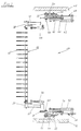
- a device 1 for stacking folded, zigzag-shaped sheets 3 stored one inside the other comprises, as shown in FIG. 1, two sets of rolls 4 and 5 for the individually or web-arriving sheets 3 and two folding cylinders 6, 7, of which the sheets 3 are placed with their folds alternately on the right and left on a lowerable support device serving as a stacking table 8.
- This is also done using separating and auxiliary carrying devices 9, 10, each of which has separating and carrying forks 11, 12 and whose function is basically known, as is the function of scraper fingers 13 and 14 which cooperate with folding cylinders 6, 7 in the formation of folds and stacking are.
- the supporting device serving as a stacking table 8 consists of two stack carrying devices 15, 16 arranged opposite one another (FIG. 1). Basically, the two separating and auxiliary carrying devices 9, 10 and the two stack carrying devices 15, 16 are in principle arranged in mirror image to a central plane 17 and are thus from two opposite sides 18, 19 (FIGS. 4, 5) during the stack formation and effective for stacking.
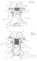
- the cloths 3 are carried off-center and in sufficient width, especially in the area of mutually opposite edges 20, 21 (FIG. 5), during the stack formation and during stack stacking. This applies both to the finished stack 2 and to a stack 2 'which is still being created (FIGS. 6 and 7).
- a stack 2 is separated during the continuous stack formation and from the next stack 2 ′ which is being formed from the two sides 18, 19.
- the stack carrying devices 15 and 16 have carrying forks 22 and 23, which are arranged on supports 24, 25 and are directly supporting, for carrying the nascent stack 2 '(FIG. 4) or the finished stack 2 (FIG. 5) are movable together in the stroke direction of the stack 2 and transversely thereto, as is also indicated by the double arrows a and b in FIG. 8.
- the stacking and carrying devices 15, 16 are therefore able to deliver a stack 2 onto a conveyor belt 26 running directly below it, for which purpose their carrying forks 22 and 23 are moved from the position according to FIG. 7 are moved away from each other in the direction of the double arrow b in FIG. 8.
- the carrying forks 22, 23 are pulled out from under the stack 2 in opposite directions or in the direction of the sides 18 and 19 and the stack 2 sinks onto the conveyor belt 26. At the same time, the bottom cloth 3 is pulled tight (FIG. 7).
- the separating and carrying forks 11, 12 belonging to the two separating and auxiliary carrying devices 9 and 10 also overlap the stack 2 from the two mutually opposite sides 18 and 19, when they are pushed as separating elements when the required stack height is reached between two stored cloths 3.
- the separating and carrying forks 11 and 12 then also lie only partially on the finished stack 2 and only overlap it from the edges 20, 21, as shown in the figures 1, 5 and 6 is shown.
- the separating and carrying forks 11, 12 each support and support the nascent stack 2 'primarily off-center, as is the case with the carrying forks 22 and 23.
- the separating and carrying forks 11, 12 are finally displaceable at an angle to the stroke direction of the stack carrying devices 15, 16 and pivotally mounted on two supports 27 and 28, respectively, and together with the respective supports 27, 28 in the lifting direction of the stack carrying devices 15, 16 movable in a guide 29, 30.
- Each stack-carrying device 15, 16 also comprises two carriers 31, 32 which can be moved along the same guides 29, 30 in the lifting direction.
- the separating and carrying forks 11, 12 each have fingers 11 'and 12', and equally the carrying forks 22, 23 are each provided with fingers 22 'and 23' (FIG. 4).
- the fingers 11 'and 12' are arranged offset to the fingers 22 'and 23' transversely to the lifting movement of the carrying forks 22, 23, that is to say transversely to the axis of the guides 29, 30.
- the wiper fingers 13 and 14 are offset from the fingers 11 'and 12' and aligned with the fingers 22 'and 23'. It is thereby achieved that the separating and carrying forks 11, 12 can both reach between the stripper fingers 13, 14 (FIG. 4) and also dip into the carrying forks 22, 23 (FIG. 8).
- shaft walls 52, 53 (FIG. 1 and FIG. 5) have a stabilizing effect.
- the shaft walls 52, 53 are further provided with slots, not shown, through which the fingers 11 ', 12' and 22 ', 23' reach.
- the supports 27, 28 and 31, 32 used for storage and guidance have rollers 33 and can be moved along the guides 29 and 30 with the aid of these rollers 33.
- drives 34 and 35 also serve, for example in the form of chain or belt drives with associated electric motors 36 and 37 (FIGS. 1, 2).
- the separating and carrying fork 12 - and the same applies to the other separating and carrying fork 11 - is supported with each of its ends 38, 39 on a respective carrier 28 and is thus supported on two in FIG. 1 guides 30 arranged one behind the other.
- a pneumatic drive 43 for example, is used to move the separating and carrying fork 12, which engages on the guide element 41 and moves or displaces the separating and carrying fork 12 via this.
- the two ends 38 and 39 of the separation and carrying fork 12 are finally pivotally mounted in the two associated holders 42 and are each with the help of another, for. B. pneumatic drive 44 is pivoted.
- rollers 33 On the respective carrier 32 of the stack carrying device 16 there are rollers 33, with the aid of which the carrier 32 can be moved along the guide 30. Both guides 30 are attached to parts 45 and 46 of the machine frame 47.
- each carrier 32 has carrying and guide rollers 48 for a guide element 49, on the free end 50 of which the carrying fork 23 is attached.
- a pneumatic drive 51 for example, is supported on each carrier 32. Together they serve to move the carrying fork 23.
- FIG. 8 finally shows the movements of the two stripper fingers 13 and 14 which are effective during the folding and depositing process, and from FIG. 9 details are again shown in which form the separating and carrying forks 11 and 12 move.
- the separating and carrying forks 11, 12 can be pivoted and according to the two double arrows d they can be moved in the lifting direction of the stack 2.
- the separating and carrying forks 11, 12 can be moved obliquely to the lifting direction in the direction of the double arrows e.
- FIG. 10 The position of the individual sheets 3 between the shaft walls 52, 53 in connection with fingers 11 'or 12' of the two separating and carrying forks 11 or 12 and the fingers 22 'used according to a preferred embodiment is shown schematically in FIG. 10. or 23 'of the two carrying forks 22 and 23.
- edge part 3 'of the bottom cloth 3 of the nascent stack 2' hangs over the free edge of the fingers 11 'of the separating and carrying fork 11 when the complete stack 2 is removed downwards.
- the same applies to the bottom cloth 3 of the stack 2 because the edge part 3 'of the cloth 3 located below the fingers 23' also hangs down there during the downward movement of the stack 2.
- the edge part 3 'of the To reach the bottom cloth 3 the edge part 3 'is blown shortly before the stack 2 is placed on a tray or on the conveyor belt 26 with the aid of a flow medium or with the aid of air. This is preferably done in such a way that the edge part bears from below on the carrying fork 22 or on its finger 22 ', as shown in FIG. 7.
- the folded-over edge part 3 'of the bottom cloth 3 results in an additional folded edge 3' 'which can later be used in a dispenser container as a grip edge for pulling out the first cloth.
- blowing nozzles 23' ' are provided on the fingers 23' of the opposite carrying fork 23 (FIG. 5).
- the stack 2 is preferably gripped under from a side 18 as it is being lowered and when it is placed on the deposit or on the conveyor belt 26, over its middle or over half, for which purpose the fingers 22 ′ have a sufficient length.
- each separating and carrying fork 11, 12 is assigned two carriers 27 and 28 and the other parts arranged on the respective carriers.
- the device 1 comprises two carriers 27 and two carriers 28 and two carriers 31 and 32 each.
- each separating and carrying fork 11 or 12 can, for. B. can also be arranged together with the remaining parts on a single carrier.
- blowing device 54 are provided for generating compressed air for the blowing nozzles 23 ′′, without having to go into these details in greater detail here.
Landscapes
- Engineering & Computer Science (AREA)
- Mechanical Engineering (AREA)
- Folding Of Thin Sheet-Like Materials, Special Discharging Devices, And Others (AREA)
- Pile Receivers (AREA)
Applications Claiming Priority (2)
| Application Number | Priority Date | Filing Date | Title |
|---|---|---|---|
| DE4419989 | 1994-06-08 | ||
| DE4419989A DE4419989C2 (de) | 1994-06-08 | 1994-06-08 | Verfahren und Vorrichtung zum Stapeln von gefalteten Tüchern |
Publications (3)
| Publication Number | Publication Date |
|---|---|
| EP0686593A2 true EP0686593A2 (fr) | 1995-12-13 |
| EP0686593A3 EP0686593A3 (fr) | 1997-01-29 |
| EP0686593B1 EP0686593B1 (fr) | 2000-08-16 |
Family
ID=6520072
Family Applications (1)
| Application Number | Title | Priority Date | Filing Date |
|---|---|---|---|
| EP95107899A Expired - Lifetime EP0686593B1 (fr) | 1994-06-08 | 1995-05-24 | Méthode et appareil pour empiler |
Country Status (4)
| Country | Link |
|---|---|
| US (1) | US5730695A (fr) |
| EP (1) | EP0686593B1 (fr) |
| JP (1) | JP3466000B2 (fr) |
| DE (2) | DE4419989C2 (fr) |
Families Citing this family (50)
| Publication number | Priority date | Publication date | Assignee | Title |
|---|---|---|---|---|
| US6176068B1 (en) | 1998-04-23 | 2001-01-23 | Bki Holding Corporation | Packaging a strip of material in layers with intervening splices |
| US6321511B1 (en) | 1988-05-20 | 2001-11-27 | Bki Holding Corporation | Packaging a strip of material with compression to reduce volume |
| US6729471B2 (en) | 1997-06-16 | 2004-05-04 | Bki Holding Corporation | Packaging a strip of material with compression to reduce volume |
| US6263814B1 (en) | 1997-07-08 | 2001-07-24 | Bki Holding Corporation | Strip of material with splices and products formed therefrom |
| US6336307B1 (en) | 1997-10-09 | 2002-01-08 | Eki Holding Corporation | Method of packaging a strip of material for use in cutting into sheet elements arranged end to end |
| FI110681B (fi) | 1998-01-02 | 2003-03-14 | Bki Holding Corp | Menetelmä rainan pakkaamiseksi |
| US6321512B1 (en) | 1999-03-08 | 2001-11-27 | Bki Holding Corporation | Method of packaging a strip of material |
| US6293075B1 (en) | 1999-03-08 | 2001-09-25 | Bki Holding Corporation | Packaging a strip of material |
| US6322315B1 (en) | 1999-10-04 | 2001-11-27 | C.G. Bretting Manufacturing Company, Inc. | Web stacker and separator apparatus and method |
| US6254522B1 (en) | 1999-10-05 | 2001-07-03 | C. G. Bretting Manufacturing Co., Inc. | Separator finger apparatus |
| JP3735009B2 (ja) * | 2000-05-31 | 2006-01-11 | 富士ゼロックス株式会社 | 用紙折り畳み機構 |
| ATE356776T1 (de) * | 2001-03-23 | 2007-04-15 | Bki Holding Corp | Verpacken einer materialbahn mit variierender breite |
| US7470102B2 (en) * | 2001-07-27 | 2008-12-30 | C.G. Bretting Manufacturing Co., Inc. | Apparatus and method for insertion of separating means into a forming stack of sheets discharged from a starwheel assembly |
| US6832886B2 (en) | 2001-07-27 | 2004-12-21 | C. G. Bretting Manufacturing Co., Inc. | Apparatus and method for stacking sheets discharged from a starwheel assembly |
| US6884209B2 (en) * | 2002-09-10 | 2005-04-26 | American Trade Names & Patents Llc | Apparatus and method for folding and stacking napkins |
| ES2319393T3 (es) * | 2002-10-31 | 2009-05-07 | M T C - Macchine Trasformazione Carta S.R.L. | Metodo y aparato para separacion de pilas de hojas interplegadas. |
| ITFI20030037A1 (it) * | 2003-02-12 | 2004-08-13 | Perini Fabio Spa | Macchina piegatrice per la produzione di manufatti in foglio, |
| ES2278134T3 (es) * | 2003-05-15 | 2007-08-01 | M T C - Macchine Trasformazione Carta S.R.L. | Rodillo plegador y metodo de plegado para maquinas convertidoras de papel. |
| ITFI20030185A1 (it) * | 2003-07-04 | 2005-01-05 | Perini Fabio Spa | Macchina piegatrice con dispositivo trasferitore dei |
| US6877740B2 (en) * | 2003-07-30 | 2005-04-12 | C.G. Bretting Manufacturing Company, Inc. | Starwheel feed apparatus and method |
| EP1640305B1 (fr) | 2004-09-22 | 2012-07-18 | MTC - Macchine Trasformazione Carta Srl | Procédé et dispositif pour la séparation des feuilles d'une flexibilité haute repliées l'une dans l'autre |
| US7097896B2 (en) * | 2004-09-30 | 2006-08-29 | Kimberly-Clark Worldwide, Inc. | Interleaved towel fold configuration |
| US8083097B2 (en) * | 2004-09-30 | 2011-12-27 | Kimberly-Clark Worldwide, Inc | Interleaved towel fold configuration |
| US20060157495A1 (en) * | 2004-12-23 | 2006-07-20 | Reddy Kiran K K | Easy open folded article |
| US7306554B2 (en) * | 2005-01-13 | 2007-12-11 | C.G. Bretting Manufacturing Co., Inc. | Method of forming a stack of interfolded sheets of web |
| NL2000024C2 (nl) * | 2006-03-13 | 2007-09-14 | Johannes Jacobus Mar Oerlemans | Vouwinrichting voor het vouwen van textiel of ander vouwbaar materiaal. |
| ITBO20060291A1 (it) * | 2006-04-14 | 2007-10-15 | Tech S R L S | Apparecchiatura per la piegatura ordinata di nastri. |
| US7717839B2 (en) * | 2008-04-04 | 2010-05-18 | C.G. Bretting Manufacturing Co., Inc. | Multi-path interfolding apparatus |
| DE102008025888A1 (de) * | 2008-05-29 | 2009-12-24 | Bhs Corrugated Maschinen- Und Anlagenbau Gmbh | Falteinrichtung |
| DE102008025890A1 (de) * | 2008-05-29 | 2009-12-24 | Bhs Corrugated Maschinen- Und Anlagenbau Gmbh | Kontinuierlicher Faltprozess |
| IT1394385B1 (it) * | 2009-06-22 | 2012-06-15 | Teknoweb S R L | Sistema perfezionato per raggruppare ed espellere da una linea di produzione principale pacchetti multistrato di salviettine monouso. |
| KR100937893B1 (ko) * | 2009-07-23 | 2010-01-21 | 주식회사 크린N | 비닐백 절첩 적층장치 |
| IT1395061B1 (it) * | 2009-08-05 | 2012-09-05 | Teknoweb S R L | Dispositivo impilatore per gruppi di salviettine monouso |
| TW201111586A (en) * | 2009-09-21 | 2011-04-01 | Chan Li Machinery Co Ltd | Folding device of textile products |
| IT1396133B1 (it) * | 2009-10-13 | 2012-11-16 | Tissuewell S R L | Metodo per la separazione automatica di pacchetti di articoli in foglio ripiegati in una macchina interfoliatrice. |
| US8240653B2 (en) * | 2009-12-30 | 2012-08-14 | C.G. Bretting Manufacturing Co., Inc. | High speed interfolder separator |
| US8282090B2 (en) * | 2009-12-30 | 2012-10-09 | C.G. Bretting Manufacturing Co., Inc. | High speed interfolder separator |
| US8333370B2 (en) | 2010-04-14 | 2012-12-18 | C.G. Bretting Manufacturing Co., Inc. | Separator belt finger count apparatus and method |
| US8490958B2 (en) | 2010-04-14 | 2013-07-23 | C.G. Bretting Manufacturing Co., Inc. | Separator belt finger count apparatus and method |
| JP5732223B2 (ja) * | 2010-09-30 | 2015-06-10 | ユニ・チャーム株式会社 | ウェットワイプスの製造方法及び製造装置 |
| US20120190524A1 (en) * | 2010-12-23 | 2012-07-26 | C.G. Bretting Manufacturing Co., Inc. | Folding apparatus and method |
| US8931618B2 (en) | 2011-02-08 | 2015-01-13 | C.G. Bretting Manufacturing Co., Inc. | Small and bulk pack napkin separator |
| US9896295B2 (en) * | 2014-11-25 | 2018-02-20 | A.G. Stacker Inc. | Buffer, stacking system including the buffer, and method of buffering |
| ITUB20153013A1 (it) * | 2015-08-07 | 2017-02-07 | Martini Domenico | Gruppo di trasferimento in una macchina per interfogliato e relativo metodo di utilizzo |
| CN106629220A (zh) * | 2015-10-28 | 2017-05-10 | 金红叶纸业集团有限公司 | 用于分隔层叠纤维制品的装置及方法 |
| US10449746B2 (en) | 2016-06-27 | 2019-10-22 | C. G. Bretting Manufacturing Co., Inc. | Web processing system with multiple folding arrangements fed by a single web handling arrangement |
| BR112020021392A2 (pt) | 2018-04-27 | 2021-01-26 | Fabio Perini S.P.A. | rolo dobrável e máquina compreendendo o dito rolo |
| IT202100026912A1 (it) * | 2021-10-20 | 2023-04-20 | Ot Lucca S R L | Sistema per il supporto e la movimentazione di una pila di fogli interfogliati durante la produzione di prodotti cartacei in pile di fogli interfogliati in una macchina interfogliatrice |
| IT202100030209A1 (it) * | 2021-11-30 | 2023-05-30 | Ot Lucca S R L | Metodo e apparecchiatura per separare due pile successive di fogli interfogliati del tipo uniti da una linea o punto di prefrattura e per ottenere un pacco di fogli interfogliati in cui un foglio estremo del pacco e' ripiegato a definire un lembo di presa per una estrazione facilitata dei fogli dal pacco |
| CN119460292A (zh) * | 2025-01-16 | 2025-02-18 | 江苏环鼎纺织科技有限公司 | 一种纺织产品的装箱设备 |
Citations (2)
| Publication number | Priority date | Publication date | Assignee | Title |
|---|---|---|---|---|
| US4770402A (en) | 1987-04-17 | 1988-09-13 | C. G. Bretting Manufacturing Company | Clip separator for interfolded sheets |
| DE3927422A1 (de) | 1989-08-19 | 1991-02-21 | Winkler Duennebier Kg Masch | Verfahren und vorrichtung zur herstellung von zahlgerechten teilstapeln |
Family Cites Families (13)
| Publication number | Priority date | Publication date | Assignee | Title |
|---|---|---|---|---|
| DE1278450B (de) * | 1966-10-12 | 1968-09-26 | Leipzig Veb Druckmasch Werke | Falzvorrichtung an Rollen-Rotations-druckmaschinen fuer einen zweiten Querfalz |
| DE1957337A1 (de) * | 1968-11-18 | 1970-06-18 | Thorsted Maskinfabrik As | Stapel- und Bindemaschine fuer Zeitungen |
| US4053150A (en) * | 1976-03-08 | 1977-10-11 | Cornelius Printing Co. | Folder apparatus |
| EP0243799B1 (fr) * | 1986-04-30 | 1990-10-31 | Bielomatik Leuze GmbH + Co. | Dispositif de pliage de bandes |
| US4721295A (en) * | 1986-08-12 | 1988-01-26 | Kimberly-Clark Corporation | Apparatus and process for separating stacks of sheets into bundles |
| US4824426A (en) * | 1987-05-11 | 1989-04-25 | Paper Converting Machine Company | Method and apparatus for interfolding webs |
| US4874158A (en) * | 1988-06-20 | 1989-10-17 | C. G. Bretting Manufacturing Co., Inc. | Dispensing fold improvement for a clip separator |
| DE3923436A1 (de) * | 1989-07-15 | 1991-01-24 | Winkler Duennebier Kg Masch | Verfahren und vorrichtung zum herstellen von papierstapeln |
| DE3925623A1 (de) * | 1989-08-02 | 1991-02-07 | Winkler Duennebier Kg Masch | Vorrichtung zum bilden von stapeln aus tuechern od. dgl. aus faserstoffen |
| CA2105769C (fr) * | 1991-03-27 | 1995-03-21 | Kasimir Kober | Construction de plieuse |
| WO1993001060A1 (fr) * | 1991-07-04 | 1993-01-21 | Gunze Limited | Systeme assurant la disposition de feuilles de papier imprimees |
| EP0586802B1 (fr) * | 1992-07-22 | 1996-10-23 | Ferag AG | Dispositif pour empiler des produits imprimés pliés |
| US5299793A (en) * | 1992-11-23 | 1994-04-05 | C. G. Bretting Manufacturing Company, Inc. | Multi-panel refolding transfer system with rotating transfer clamp |
-
1994
- 1994-06-08 DE DE4419989A patent/DE4419989C2/de not_active Expired - Fee Related
-
1995
- 1995-05-24 DE DE59508637T patent/DE59508637D1/de not_active Expired - Fee Related
- 1995-05-24 EP EP95107899A patent/EP0686593B1/fr not_active Expired - Lifetime
- 1995-06-07 US US08/485,102 patent/US5730695A/en not_active Expired - Lifetime
- 1995-06-07 JP JP16466895A patent/JP3466000B2/ja not_active Expired - Fee Related
Patent Citations (2)
| Publication number | Priority date | Publication date | Assignee | Title |
|---|---|---|---|---|
| US4770402A (en) | 1987-04-17 | 1988-09-13 | C. G. Bretting Manufacturing Company | Clip separator for interfolded sheets |
| DE3927422A1 (de) | 1989-08-19 | 1991-02-21 | Winkler Duennebier Kg Masch | Verfahren und vorrichtung zur herstellung von zahlgerechten teilstapeln |
Also Published As
| Publication number | Publication date |
|---|---|
| EP0686593A3 (fr) | 1997-01-29 |
| JP3466000B2 (ja) | 2003-11-10 |
| DE4419989C2 (de) | 1997-10-02 |
| DE4419989A1 (de) | 1995-12-14 |
| DE59508637D1 (de) | 2000-09-21 |
| US5730695A (en) | 1998-03-24 |
| EP0686593B1 (fr) | 2000-08-16 |
| JPH08175748A (ja) | 1996-07-09 |
Similar Documents
| Publication | Publication Date | Title |
|---|---|---|
| EP0686593A2 (fr) | Méthode et appareil pour empiler | |
| EP0187344B1 (fr) | Procédé et dispositif pour produire des piles individuelles composées d'une bande en accordéon | |
| EP0189090B1 (fr) | Dispositif de pliage de bandes | |
| EP0986478B1 (fr) | Procédé pour enfiler une bande partielle de papier | |
| EP0050860B1 (fr) | Appareil pour former et empiler des segments séparés d'une bande de feuille tubulaire | |
| CH652106A5 (de) | Verfahren und vorrichtung zum bilden von einzelnen stapeln aus einer endlosen bahn. | |
| DE2827540B1 (de) | Stapelvorrichtung fuer Faltschachteln | |
| DE3046107A1 (de) | Stapelvorrichtung fuer boegen | |
| EP0623542A1 (fr) | Dispositif pour empiler un chant de feuilles imprimées | |
| DE2852603A1 (de) | Verfahren und vorrichtung zum stapeln von pappzuschnitten | |
| DE3852574T2 (de) | Verfahren und Vorrichtung zum Vereinzeln einer vorherbestimmten Zahl von flachen Objekten, wie Papierblättern. | |
| EP0243799B1 (fr) | Dispositif de pliage de bandes | |
| DE2436662C3 (de) | Vorrichtung zum Herstellen von Stapelpackungen mit zick-zack-artig ineinander gefalteten Papiertüchern | |
| EP0278120B1 (fr) | Plieuse en accordéon | |
| DE69812217T2 (de) | Maschine zum Stapeln von Bögen in Bündeln | |
| CH680363A5 (fr) | ||
| DE1277140B (de) | Vorrichtung zum Stapeln und Transportieren von flachen Gegenstaenden, insbesondere Papiertuechern | |
| DE3635895A1 (de) | Verfahren und vorrichtung zum trennen einer zick-zack-foermig gefalteten materialbahn | |
| DE3219693A1 (de) | Vorrichtung zur bildung von verarbeitungsfaehigen teilstapeln aus folienbogen, insbesondere papierbogen | |
| DE3401819A1 (de) | Beschickungsvorrichtung fuer eine mit einer kontinuierlich arbeitenden einzugseinrichtung versehene bogenverarbeitungsmaschine | |
| EP0741101B1 (fr) | Méthode pour séparer une pile de cahiers dans un empileur et empileur pour la mise en oeuvre de cette méthode | |
| WO2004002833A1 (fr) | Installation servant a emballer une bande souple disposee en couches de boucles en zigzag, en particulier d'une bande textile | |
| DE2940399C2 (de) | Vorrichtung zum Stapeln von Kunststoffbeuteln | |
| DE634388C (de) | Maschine zum Abschneiden und Aufkleben von Stoff- und anderen Mustern | |
| DE3303234C2 (de) | Vorrichtung zum verpackungsgerechten Zusammenlegen von Tüchern od. dgl. |
Legal Events
| Date | Code | Title | Description |
|---|---|---|---|
| PUAI | Public reference made under article 153(3) epc to a published international application that has entered the european phase |
Free format text: ORIGINAL CODE: 0009012 |
|
| AK | Designated contracting states |
Kind code of ref document: A2 Designated state(s): DE FR GB IT |
|
| PUAL | Search report despatched |
Free format text: ORIGINAL CODE: 0009013 |
|
| AK | Designated contracting states |
Kind code of ref document: A3 Designated state(s): DE FR GB IT |
|
| 17P | Request for examination filed |
Effective date: 19970319 |
|
| 17Q | First examination report despatched |
Effective date: 19980626 |
|
| GRAG | Despatch of communication of intention to grant |
Free format text: ORIGINAL CODE: EPIDOS AGRA |
|
| GRAG | Despatch of communication of intention to grant |
Free format text: ORIGINAL CODE: EPIDOS AGRA |
|
| GRAH | Despatch of communication of intention to grant a patent |
Free format text: ORIGINAL CODE: EPIDOS IGRA |
|
| GRAH | Despatch of communication of intention to grant a patent |
Free format text: ORIGINAL CODE: EPIDOS IGRA |
|
| GRAA | (expected) grant |
Free format text: ORIGINAL CODE: 0009210 |
|
| AK | Designated contracting states |
Kind code of ref document: B1 Designated state(s): DE FR GB IT |
|
| GBT | Gb: translation of ep patent filed (gb section 77(6)(a)/1977) |
Effective date: 20000824 |
|
| REF | Corresponds to: |
Ref document number: 59508637 Country of ref document: DE Date of ref document: 20000921 |
|
| ET | Fr: translation filed | ||
| ITF | It: translation for a ep patent filed | ||
| PLBE | No opposition filed within time limit |
Free format text: ORIGINAL CODE: 0009261 |
|
| STAA | Information on the status of an ep patent application or granted ep patent |
Free format text: STATUS: NO OPPOSITION FILED WITHIN TIME LIMIT |
|
| 26N | No opposition filed | ||
| REG | Reference to a national code |
Ref country code: GB Ref legal event code: IF02 |
|
| PGFP | Annual fee paid to national office [announced via postgrant information from national office to epo] |
Ref country code: DE Payment date: 20080724 Year of fee payment: 14 |
|
| PGFP | Annual fee paid to national office [announced via postgrant information from national office to epo] |
Ref country code: GB Payment date: 20080522 Year of fee payment: 14 |
|
| PGFP | Annual fee paid to national office [announced via postgrant information from national office to epo] |
Ref country code: IT Payment date: 20090527 Year of fee payment: 15 |
|
| GBPC | Gb: european patent ceased through non-payment of renewal fee |
Effective date: 20090524 |
|
| REG | Reference to a national code |
Ref country code: FR Ref legal event code: ST Effective date: 20100129 |
|
| PG25 | Lapsed in a contracting state [announced via postgrant information from national office to epo] |
Ref country code: FR Free format text: LAPSE BECAUSE OF NON-PAYMENT OF DUE FEES Effective date: 20090602 |
|
| PGFP | Annual fee paid to national office [announced via postgrant information from national office to epo] |
Ref country code: FR Payment date: 20080519 Year of fee payment: 14 |
|
| PG25 | Lapsed in a contracting state [announced via postgrant information from national office to epo] |
Ref country code: GB Free format text: LAPSE BECAUSE OF NON-PAYMENT OF DUE FEES Effective date: 20090524 |
|
| PG25 | Lapsed in a contracting state [announced via postgrant information from national office to epo] |
Ref country code: DE Free format text: LAPSE BECAUSE OF NON-PAYMENT OF DUE FEES Effective date: 20091201 |
|
| PG25 | Lapsed in a contracting state [announced via postgrant information from national office to epo] |
Ref country code: IT Free format text: LAPSE BECAUSE OF NON-PAYMENT OF DUE FEES Effective date: 20100524 |