EP0686710A2 - Montage de galvanisation pour le revêtement d'éléments - Google Patents
Montage de galvanisation pour le revêtement d'éléments Download PDFInfo
- Publication number
- EP0686710A2 EP0686710A2 EP95107451A EP95107451A EP0686710A2 EP 0686710 A2 EP0686710 A2 EP 0686710A2 EP 95107451 A EP95107451 A EP 95107451A EP 95107451 A EP95107451 A EP 95107451A EP 0686710 A2 EP0686710 A2 EP 0686710A2
- Authority
- EP
- European Patent Office
- Prior art keywords
- electroplating
- magazine
- electrodes
- magazine according
- distributor disc
- Prior art date
- Legal status (The legal status is an assumption and is not a legal conclusion. Google has not performed a legal analysis and makes no representation as to the accuracy of the status listed.)
- Granted
Links
- 238000007747 plating Methods 0.000 title description 5
- 238000009713 electroplating Methods 0.000 claims abstract description 53
- 238000000576 coating method Methods 0.000 claims abstract description 15
- 239000011248 coating agent Substances 0.000 claims abstract description 13
- 239000000463 material Substances 0.000 claims description 3
- 238000003032 molecular docking Methods 0.000 claims description 2
- 239000002184 metal Substances 0.000 claims 1
- 238000000034 method Methods 0.000 description 7
- 238000001035 drying Methods 0.000 description 3
- 238000005246 galvanizing Methods 0.000 description 2
- 239000010410 layer Substances 0.000 description 2
- 210000003739 neck Anatomy 0.000 description 2
- 239000011241 protective layer Substances 0.000 description 2
- RYGMFSIKBFXOCR-UHFFFAOYSA-N Copper Chemical compound [Cu] RYGMFSIKBFXOCR-UHFFFAOYSA-N 0.000 description 1
- 230000002411 adverse Effects 0.000 description 1
- 230000015572 biosynthetic process Effects 0.000 description 1
- 210000000078 claw Anatomy 0.000 description 1
- 229910052802 copper Inorganic materials 0.000 description 1
- 239000010949 copper Substances 0.000 description 1
- PCHJSUWPFVWCPO-UHFFFAOYSA-N gold Chemical compound [Au] PCHJSUWPFVWCPO-UHFFFAOYSA-N 0.000 description 1
- 229910052737 gold Inorganic materials 0.000 description 1
- 239000010931 gold Substances 0.000 description 1
- 230000007774 longterm Effects 0.000 description 1
- 238000004519 manufacturing process Methods 0.000 description 1
- 238000004886 process control Methods 0.000 description 1
- 238000003908 quality control method Methods 0.000 description 1
- 238000007788 roughening Methods 0.000 description 1
- 238000005476 soldering Methods 0.000 description 1
- 230000035899 viability Effects 0.000 description 1
Images
Classifications
-
- C—CHEMISTRY; METALLURGY
- C25—ELECTROLYTIC OR ELECTROPHORETIC PROCESSES; APPARATUS THEREFOR
- C25D—PROCESSES FOR THE ELECTROLYTIC OR ELECTROPHORETIC PRODUCTION OF COATINGS; ELECTROFORMING; APPARATUS THEREFOR
- C25D17/00—Constructional parts, or assemblies thereof, of cells for electrolytic coating
- C25D17/06—Suspending or supporting devices for articles to be coated
Definitions
- the invention relates to a galvanizing magazine for coating components according to the preamble of claim 1.
- the electroplating process is a widespread process if the application of protective layers to surfaces of large and small parts is intended to improve their material properties.
- the process control before, during and after the coating and the devices used for this purpose are essential for the economic viability of such processes.
- drum-like electroplating frames are often used, which are filled with the components to be coated in bulk and inserted into the electroplating bath with the horizontal drum axis. As a result, large series of components can be surface coated economically.
- the object of the invention is to provide a generic electroplating magazine for coating components, with which components can be coated in large numbers with coating quality that is as reproducible as possible.
- the electroplating magazine according to the invention has the advantage that the regular or uniform spacing of the component receptacles in the circumferential and axial directions on the outer circumference of the drum-shaped electroplating magazine allows a defined spacing from the anode of the electroplating bath to be maintained. On the one hand, this enables a reproducible and controllable coating quality of the components in a large series run, on the other hand, the electroplating magazine is accessible to automated assembly and dismantling through the defined spaced arrangement of the component receptacles on the electrodes, so that individual quality control of the components can be carried out economically.
- the external component receptacles also ensure that the electroplating magazine can be used in the process processes that do not directly belong to the electroplating process, such as rinsing, roughening and drying, without the need to implement the components. Further advantageous embodiments of the invention result from the features of claims 2 to 20.
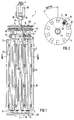
- the electroplating magazine 1 has a coaxial, circular distributor disk 4 made of copper, which in turn is connected to a likewise disk-shaped holder 6 via an electrically insulating and axially extending central body 5.
- Ten rod-shaped electrodes 3 are arranged in a revolving manner around the central body 5 in the space between the distributor disk 4 which is perpendicular to the central body 5 and the holder 6 which is likewise perpendicular to the central body 5.
- the electrodes 3 are each plug-connected at their two ends via base parts 7 formed on the electrode side to the holder 6 in a position-centering manner or fastened in an electrically conductive manner to the distributor disk 4 via screw connections 8.
- the screw connections 8, screws 9 and the internal thread 10 on the electrode side are coated with gold.
- the distributor disc 4 has circumferentially spaced and radially extending grooves 11 on the electrode side at an angle of 36 °.
- the necks 12 of the electrodes 3 receiving the internal thread 10 each protrude transversely into these grooves 11, so that after loosening the screw connections 8 when the electrodes 3 are tilted around their base parts 7, the necks 12 move radially out of the grooves 11 and thus the electrodes 3 to the electroplating magazine 1 can be removed.
- the electroplating magazine 1 can be loaded and dismounted with electrodes 3 with little effort. Only when assembling the For an optimal electrical connection, electrodes 3 must ensure a tight screw connection 8.
- a toothed ring 13 is formed on the outer circumference of the distributor disk for rotating the electroplating magazine 1. If the electrodes 3 are to be loaded or dismounted by a device (not shown further), the component receptacles 14 provided for fixing the small components 2 on the electrodes 3 can be brought into an exact loading or dismounting position by rotating the electroplating magazine 1 about its longitudinal axis L. to be brought. In addition, the electroplating magazine 1 can be rotated during drying, rinsing or coating to increase the effectiveness.
- An electrical cable is provided as an additional electrical line connection 15 between the electrode 3 and the distributor plate 4, which ensures the current supply even when the screw connections 8 are in poor contact.
- the line connection 15 is shown representative of all other electrodes only on one electrode 3 '.
- a soldering lug 16 establishes the secure connection between the electrode 3 'and the electrical cable.
- a shaft 17 is formed on the distributor disk 4 beyond the electrodes 3 and has a contact surface 19 that widens conically to the shaft end 18.
- the contact surface 19 serves on the one hand as a power connection and as a holding force-transmitting element of the plating magazine 1.
- the plating magazine 1 can be used during the coating process, during rinsing and drying instead of via the rotating ring 13 drive over the shaft 17.
- the large-area contact surface 19 ensures a low-resistance current transfer during the coating process.
- the electrodes 3 essentially each consist of an electrically conductive electrode rod 21, an aperture 22 having the component receptacles 14 and a rod-shaped permanent magnet 23 located within the electrode rod 21.
- the cover 22 has a row of boreholes serving as component receptacles 14, into which the small components 2 are inserted and permanent magnets 23 extending along the electrode rod 21 can be held on the electrode 3 with electrical contact.
- the row of boreholes R is aligned parallel to the longitudinal axis L of the magazine, which accommodates the accessibility during the automatic loading and unloading.
- the component receptacles 14 are evenly spaced from one another, thereby eliminating electrical or magnetic disturbances which adversely affect the coating.
- the borehole axes A of the component receptacles 14 are essentially perpendicular to the longitudinal axis L of the magazine, which likewise promotes reproducibly good layer formation and facilitates automatic loading and unloading.
- these each have 24 pin holes as positioning means.
- the material of the central body 5 and the holder 6 is made of an electrochemically resistant plastic.
- the electrode rods 21 are provided with a protective layer, and the cover 22 is made of an electrochemically resistant plastic.
- bracket 6 For a trouble-free function of the electroplating magazine 1 during transportation and movement during the process steps as well as during loading and unloading, a bracket 6 is used. Axially concentric running surface 25 and a coaxial centering bore 26, which is provided on the holder 6 on the other side of the central body 5.
Landscapes
- Chemical & Material Sciences (AREA)
- Engineering & Computer Science (AREA)
- Chemical Kinetics & Catalysis (AREA)
- Electrochemistry (AREA)
- Materials Engineering (AREA)
- Metallurgy (AREA)
- Organic Chemistry (AREA)
- Electroplating Methods And Accessories (AREA)
- Chemically Coating (AREA)
- Coating With Molten Metal (AREA)
- Paints Or Removers (AREA)
- Electroplating And Plating Baths Therefor (AREA)
Applications Claiming Priority (2)
| Application Number | Priority Date | Filing Date | Title |
|---|---|---|---|
| DE4419984A DE4419984C2 (de) | 1994-06-08 | 1994-06-08 | Galvanisiermagazin zum Beschichten von Bauteilen |
| DE4419984 | 1994-06-08 |
Publications (3)
| Publication Number | Publication Date |
|---|---|
| EP0686710A2 true EP0686710A2 (fr) | 1995-12-13 |
| EP0686710A3 EP0686710A3 (fr) | 1996-02-07 |
| EP0686710B1 EP0686710B1 (fr) | 1998-03-04 |
Family
ID=6520067
Family Applications (1)
| Application Number | Title | Priority Date | Filing Date |
|---|---|---|---|
| EP95107451A Expired - Lifetime EP0686710B1 (fr) | 1994-06-08 | 1995-05-17 | Montage de galvanisation pour le revêtement d'éléments |
Country Status (5)
| Country | Link |
|---|---|
| US (1) | US5536377A (fr) |
| EP (1) | EP0686710B1 (fr) |
| JP (1) | JP3647508B2 (fr) |
| AT (1) | ATE163692T1 (fr) |
| DE (2) | DE4419984C2 (fr) |
Cited By (2)
| Publication number | Priority date | Publication date | Assignee | Title |
|---|---|---|---|---|
| ITBO20110257A1 (it) * | 2011-05-09 | 2012-11-10 | Roberto Zini | Apparato, particolarmente per trattamenti di galvanoplastica, galvanostegia, e simili |
| WO2018091723A3 (fr) * | 2016-11-21 | 2018-09-27 | Robert Bosch Gmbh | Composant d'injecteur muni d'un revêtement, injecteur et dispositif de revêtement |
Families Citing this family (10)
| Publication number | Priority date | Publication date | Assignee | Title |
|---|---|---|---|---|
| DE19735244B4 (de) * | 1997-08-14 | 2007-07-12 | Robert Bosch Gmbh | Verfahren und Vorrichtung zum Verchromen von Werkstücken |
| DE19822196C2 (de) * | 1998-05-16 | 2000-05-11 | Lemfoerder Metallwaren Ag | Verfahren zur selektiven bereichsweisen Beschichtung metallischer Bauteile und Vorrichtung zur Durchführung des Verfahrens |
| DE10313818A1 (de) * | 2003-03-24 | 2004-10-07 | Wieland Dental + Technik Gmbh & Co. Kg | Vorrichtung und deren Teile für die galvanische Abscheidung von dentalen Formteilen |
| KR100906951B1 (ko) * | 2008-11-04 | 2009-07-08 | 주식회사 동해씨엔텍 | 도금물 거치용 행어 |
| DE102009013467B4 (de) | 2009-03-07 | 2014-12-31 | GalvaConsult GmbH | Verfahren und Vorrichtung zum elektrochemischen Behandeln von Gut in Behandlungsvorrichtungen |
| DE102009013468A1 (de) | 2009-03-07 | 2010-09-09 | Hübel, Egon, Dipl.-Ing. (FH) | Vorrichtung und Verfahren zur Nassbehandlung von Gütern |
| KR101005852B1 (ko) * | 2010-08-18 | 2011-01-05 | 경원대학교 산학협력단 | 자동차 휠너트 도금용 자동랙킹장치 |
| CN104073852B (zh) * | 2014-06-24 | 2016-05-11 | 华晶精密制造股份有限公司 | 一种金刚石切割线生产设备的旋转磁铁机构 |
| US10960418B2 (en) | 2019-01-03 | 2021-03-30 | Production Plus Corp. | Cross bar for powder coating and electronic coating |
| CN111058079B (zh) * | 2019-12-23 | 2021-04-13 | 福耀汽车铝件(福建)有限公司 | 一种防变形挂具 |
Family Cites Families (15)
| Publication number | Priority date | Publication date | Assignee | Title |
|---|---|---|---|---|
| DE520334C (de) * | 1929-12-01 | 1931-03-10 | Langbein Pfanhauser Werke Akt | Aufhaengung von zu galvanisierenden, sperrigen, nadelartigen Waren aus magnetisierbarem Stoff |
| US2911347A (en) * | 1957-04-01 | 1959-11-03 | Intercompany Corp | Plating rack |
| US3692638A (en) * | 1970-12-21 | 1972-09-19 | Western Electric Co | Process for supporting and nonuniformly treating articles |
| CH539124A (fr) * | 1971-06-14 | 1973-07-15 | Oxy Metal Finishing Corp | Support mobile d'accrochage pour la galvanoplastie |
| DE2537362C2 (de) * | 1975-08-19 | 1986-12-04 | Schering AG, 1000 Berlin und 4709 Bergkamen | Vorrichtung zur Aufnahme von Kleinteilen zum Zwecke der galvanischen Oberflächenbehandlung |
| DE2636413A1 (de) * | 1976-08-12 | 1978-02-16 | Schering Ag | Vorrichtung zum vollstaendigen und partiellen behandeln der oberflaechen von teilen |
| FR2398124A1 (fr) * | 1977-07-20 | 1979-02-16 | Neiman Sa | Procede et dispositif de traitement electrolytique |
| JPS59190383A (ja) * | 1983-04-11 | 1984-10-29 | Nippon Denso Co Ltd | 高速部分めつき方法およびその装置 |
| JPS61227198A (ja) * | 1985-03-30 | 1986-10-09 | Max Co Ltd | プリンタ印字輪等の円形外周部にメツキする方法及びこの方法に用いるメツキ装置 |
| US4734179A (en) * | 1986-11-21 | 1988-03-29 | Trammel Gary L | Bullet plating carousel |
| JPS644499A (en) * | 1987-06-25 | 1989-01-09 | Hikifune Kk | Method and device for rotary plating |
| JPS6414499A (en) * | 1987-07-09 | 1989-01-18 | Shimizu Construction Co Ltd | Conveyor for excavation muck |
| JP2795694B2 (ja) * | 1989-09-13 | 1998-09-10 | 上村工業株式会社 | めっき処理装置のワーク保持装置 |
| US4946572A (en) * | 1989-12-27 | 1990-08-07 | Ford Motor Company | Electroplating of precision parts |
| CH683007A5 (de) * | 1990-08-17 | 1993-12-31 | Hans Henig | Verfahren zum kontinuierlichen Austausch der wässrigen Lösungen während einer Oberflächenbehandlung sowie eine Vorrichtung dazu. |
-
1994
- 1994-06-08 DE DE4419984A patent/DE4419984C2/de not_active Expired - Fee Related
-
1995
- 1995-05-17 EP EP95107451A patent/EP0686710B1/fr not_active Expired - Lifetime
- 1995-05-17 DE DE59501522T patent/DE59501522D1/de not_active Expired - Fee Related
- 1995-05-17 AT AT95107451T patent/ATE163692T1/de not_active IP Right Cessation
- 1995-06-06 JP JP13965395A patent/JP3647508B2/ja not_active Expired - Fee Related
- 1995-06-07 US US08/480,895 patent/US5536377A/en not_active Expired - Fee Related
Non-Patent Citations (1)
| Title |
|---|
| None |
Cited By (5)
| Publication number | Priority date | Publication date | Assignee | Title |
|---|---|---|---|---|
| ITBO20110257A1 (it) * | 2011-05-09 | 2012-11-10 | Roberto Zini | Apparato, particolarmente per trattamenti di galvanoplastica, galvanostegia, e simili |
| WO2018091723A3 (fr) * | 2016-11-21 | 2018-09-27 | Robert Bosch Gmbh | Composant d'injecteur muni d'un revêtement, injecteur et dispositif de revêtement |
| KR20190080894A (ko) * | 2016-11-21 | 2019-07-08 | 로베르트 보쉬 게엠베하 | 코팅층을 포함한 인젝터 부품, 인젝터, 및 코팅 장치 |
| US11401901B2 (en) | 2016-11-21 | 2022-08-02 | Robert Bosch Gmbh | Injector component having a coating, injector, as well as a device for coating |
| US12276243B2 (en) | 2016-11-21 | 2025-04-15 | Robert Bosch Gmbh | Injector component having a coating, injector, as well as a device for coating |
Also Published As
| Publication number | Publication date |
|---|---|
| DE4419984C2 (de) | 1996-10-24 |
| EP0686710B1 (fr) | 1998-03-04 |
| DE4419984A1 (de) | 1995-12-14 |
| EP0686710A3 (fr) | 1996-02-07 |
| DE59501522D1 (de) | 1998-04-09 |
| US5536377A (en) | 1996-07-16 |
| ATE163692T1 (de) | 1998-03-15 |
| JPH0841690A (ja) | 1996-02-13 |
| JP3647508B2 (ja) | 2005-05-11 |
Similar Documents
| Publication | Publication Date | Title |
|---|---|---|
| EP0686710B1 (fr) | Montage de galvanisation pour le revêtement d'éléments | |
| US3941674A (en) | Plating rack | |
| DE69314972T2 (de) | Galvanisierverfahren, Vorrichtung zur Herstellung einer Metallfolie und dabei verwendete geteilte unlösliche Elektrode | |
| EP0796663A2 (fr) | Pulvérisateur rotatif pour le revêtement assisté par voie électrostatique d'objets par des peintures ou des lacques | |
| DE2051778C3 (de) | Vorrichtung zum Galvanisieren von zylindrischen Gegenständen | |
| EP2893056B1 (fr) | Revêtement galvanique d'un produit à traiter en utilisant une anode intérieure | |
| EP1115912A2 (fr) | Dispositif pour le traitement electrochimique partiel d'objets sous forme de barres | |
| DE3822726C2 (fr) | ||
| EP0284173B1 (fr) | Barre dentaire recouverte de diamants ainsi que sa méthode de fabrication | |
| EP0690151B1 (fr) | Electrode pour le revêtement électrolytique d'éléments | |
| DE10309401A1 (de) | Vorrichtung und Verfahren zu Beschichtung von Gegenständen | |
| DE1943095A1 (de) | Austauschbare Schweisseinheit fuer automatische Schweissgeraete | |
| DE2625831A1 (de) | Vorrichtung zum festklemmen eines zu galvanisierenden gegenstandes an einem elektrischen stuetzleiter | |
| DE1172512B (de) | Haltevorrichtung fuer perforierte Tauch-trommeln bei Anlagen zur Oberflaechen-behandlung von Massenteilen in Fluessigkeiten | |
| DD153611A5 (de) | Galvanisiergeraet | |
| DE6909400U (de) | Isolierende schutzummantelung fuer an der oberflaeche mechanisch beanspruchte teile von schweissgeraeten. | |
| DE3603062A1 (de) | Vorrichtung zum halten von leiterplatten | |
| DE1796045B2 (de) | Galvanisiertrommel zur Oberflächenbehandlung von Gegenständen | |
| DE19701696C2 (de) | Vorrichtung und Verfahren zur Beschichtung eines Substrates mittels eines chemischen Gasphasenabscheideverfahrens | |
| DE2353592C3 (de) | Galvanisiertrommel | |
| DE3605486A1 (de) | Verdampfungsapparat und verwendung desselben | |
| DE1808807A1 (de) | Vorrichtung zur elektrolytischen Behandlung von Werkstuecken | |
| DE8607441U1 (de) | Vorrichtung zum Aufbringen galvanischer Überzüge | |
| DE8630804U1 (de) | Halter für Elektroden für Elektroerosionsmaschinen | |
| DE152724A (fr) |
Legal Events
| Date | Code | Title | Description |
|---|---|---|---|
| PUAI | Public reference made under article 153(3) epc to a published international application that has entered the european phase |
Free format text: ORIGINAL CODE: 0009012 |
|
| AK | Designated contracting states |
Kind code of ref document: A2 Designated state(s): AT DE FR GB IT |
|
| PUAL | Search report despatched |
Free format text: ORIGINAL CODE: 0009013 |
|
| AK | Designated contracting states |
Kind code of ref document: A3 Designated state(s): AT DE FR GB IT |
|
| 17P | Request for examination filed |
Effective date: 19960716 |
|
| GRAG | Despatch of communication of intention to grant |
Free format text: ORIGINAL CODE: EPIDOS AGRA |
|
| GRAG | Despatch of communication of intention to grant |
Free format text: ORIGINAL CODE: EPIDOS AGRA |
|
| GRAH | Despatch of communication of intention to grant a patent |
Free format text: ORIGINAL CODE: EPIDOS IGRA |
|
| 17Q | First examination report despatched |
Effective date: 19970617 |
|
| GRAH | Despatch of communication of intention to grant a patent |
Free format text: ORIGINAL CODE: EPIDOS IGRA |
|
| GRAA | (expected) grant |
Free format text: ORIGINAL CODE: 0009210 |
|
| ITF | It: translation for a ep patent filed | ||
| AK | Designated contracting states |
Kind code of ref document: B1 Designated state(s): AT DE FR GB IT |
|
| REF | Corresponds to: |
Ref document number: 163692 Country of ref document: AT Date of ref document: 19980315 Kind code of ref document: T |
|
| ET | Fr: translation filed | ||
| REF | Corresponds to: |
Ref document number: 59501522 Country of ref document: DE Date of ref document: 19980409 |
|
| GBT | Gb: translation of ep patent filed (gb section 77(6)(a)/1977) |
Effective date: 19980508 |
|
| PLBE | No opposition filed within time limit |
Free format text: ORIGINAL CODE: 0009261 |
|
| STAA | Information on the status of an ep patent application or granted ep patent |
Free format text: STATUS: NO OPPOSITION FILED WITHIN TIME LIMIT |
|
| 26N | No opposition filed | ||
| REG | Reference to a national code |
Ref country code: GB Ref legal event code: IF02 |
|
| PGFP | Annual fee paid to national office [announced via postgrant information from national office to epo] |
Ref country code: AT Payment date: 20060515 Year of fee payment: 12 |
|
| PGFP | Annual fee paid to national office [announced via postgrant information from national office to epo] |
Ref country code: FR Payment date: 20060519 Year of fee payment: 12 Ref country code: DE Payment date: 20060519 Year of fee payment: 12 |
|
| PGFP | Annual fee paid to national office [announced via postgrant information from national office to epo] |
Ref country code: GB Payment date: 20060522 Year of fee payment: 12 |
|
| PGFP | Annual fee paid to national office [announced via postgrant information from national office to epo] |
Ref country code: IT Payment date: 20060531 Year of fee payment: 12 |
|
| GBPC | Gb: european patent ceased through non-payment of renewal fee |
Effective date: 20070517 |
|
| PG25 | Lapsed in a contracting state [announced via postgrant information from national office to epo] |
Ref country code: AT Free format text: LAPSE BECAUSE OF NON-PAYMENT OF DUE FEES Effective date: 20070517 |
|
| REG | Reference to a national code |
Ref country code: FR Ref legal event code: ST Effective date: 20080131 |
|
| PG25 | Lapsed in a contracting state [announced via postgrant information from national office to epo] |
Ref country code: DE Free format text: LAPSE BECAUSE OF NON-PAYMENT OF DUE FEES Effective date: 20071201 |
|
| PG25 | Lapsed in a contracting state [announced via postgrant information from national office to epo] |
Ref country code: GB Free format text: LAPSE BECAUSE OF NON-PAYMENT OF DUE FEES Effective date: 20070517 |
|
| PG25 | Lapsed in a contracting state [announced via postgrant information from national office to epo] |
Ref country code: FR Free format text: LAPSE BECAUSE OF NON-PAYMENT OF DUE FEES Effective date: 20070531 |
|
| PG25 | Lapsed in a contracting state [announced via postgrant information from national office to epo] |
Ref country code: IT Free format text: LAPSE BECAUSE OF NON-PAYMENT OF DUE FEES Effective date: 20070517 |