EP0686718B1 - Metall-Vliesstoff und Verfahren zur dessen Herstellung - Google Patents
Metall-Vliesstoff und Verfahren zur dessen Herstellung Download PDFInfo
- Publication number
- EP0686718B1 EP0686718B1 EP95108312A EP95108312A EP0686718B1 EP 0686718 B1 EP0686718 B1 EP 0686718B1 EP 95108312 A EP95108312 A EP 95108312A EP 95108312 A EP95108312 A EP 95108312A EP 0686718 B1 EP0686718 B1 EP 0686718B1
- Authority
- EP
- European Patent Office
- Prior art keywords
- fabric
- unwoven
- metal
- fibers
- carbon
- Prior art date
- Legal status (The legal status is an assumption and is not a legal conclusion. Google has not performed a legal analysis and makes no representation as to the accuracy of the status listed.)
- Expired - Lifetime
Links
- 239000004744 fabric Substances 0.000 title claims description 81
- 239000002184 metal Substances 0.000 title claims description 65
- 229910052751 metal Inorganic materials 0.000 title claims description 65
- 238000004519 manufacturing process Methods 0.000 title claims description 11
- 239000000835 fiber Substances 0.000 claims description 58
- 229920000049 Carbon (fiber) Polymers 0.000 claims description 53
- 239000004917 carbon fiber Substances 0.000 claims description 36
- 229920005989 resin Polymers 0.000 claims description 34
- 239000011347 resin Substances 0.000 claims description 34
- VNWKTOKETHGBQD-UHFFFAOYSA-N methane Chemical compound C VNWKTOKETHGBQD-UHFFFAOYSA-N 0.000 claims description 26
- 238000009713 electroplating Methods 0.000 claims description 11
- 238000010438 heat treatment Methods 0.000 claims description 11
- 239000000463 material Substances 0.000 claims description 10
- 229910052759 nickel Inorganic materials 0.000 claims description 10
- 238000012856 packing Methods 0.000 claims description 9
- 229910052802 copper Inorganic materials 0.000 claims description 3
- 229910052742 iron Inorganic materials 0.000 claims description 3
- 230000001590 oxidative effect Effects 0.000 claims description 3
- 229910052709 silver Inorganic materials 0.000 claims description 3
- BVKZGUZCCUSVTD-UHFFFAOYSA-L Carbonate Chemical compound [O-]C([O-])=O BVKZGUZCCUSVTD-UHFFFAOYSA-L 0.000 claims 1
- 238000007747 plating Methods 0.000 description 39
- 239000011230 binding agent Substances 0.000 description 21
- PXHVJJICTQNCMI-UHFFFAOYSA-N nickel Substances [Ni] PXHVJJICTQNCMI-UHFFFAOYSA-N 0.000 description 17
- 239000007789 gas Substances 0.000 description 12
- 238000000034 method Methods 0.000 description 9
- 238000010000 carbonizing Methods 0.000 description 8
- OKTJSMMVPCPJKN-UHFFFAOYSA-N Carbon Chemical compound [C] OKTJSMMVPCPJKN-UHFFFAOYSA-N 0.000 description 7
- 239000003054 catalyst Substances 0.000 description 7
- 239000012535 impurity Substances 0.000 description 6
- XEEYBQQBJWHFJM-UHFFFAOYSA-N iron Substances [Fe] XEEYBQQBJWHFJM-UHFFFAOYSA-N 0.000 description 5
- XKRFYHLGVUSROY-UHFFFAOYSA-N Argon Chemical compound [Ar] XKRFYHLGVUSROY-UHFFFAOYSA-N 0.000 description 4
- 229910052799 carbon Inorganic materials 0.000 description 4
- 239000010949 copper Substances 0.000 description 4
- 238000005259 measurement Methods 0.000 description 4
- 230000003287 optical effect Effects 0.000 description 4
- 239000000758 substrate Substances 0.000 description 4
- 239000003822 epoxy resin Substances 0.000 description 3
- 229920000647 polyepoxide Polymers 0.000 description 3
- 230000003746 surface roughness Effects 0.000 description 3
- BFNBIHQBYMNNAN-UHFFFAOYSA-N ammonium sulfate Chemical compound N.N.OS(O)(=O)=O BFNBIHQBYMNNAN-UHFFFAOYSA-N 0.000 description 2
- 229910052921 ammonium sulfate Inorganic materials 0.000 description 2
- 229910052786 argon Inorganic materials 0.000 description 2
- 239000007795 chemical reaction product Substances 0.000 description 2
- 230000007423 decrease Effects 0.000 description 2
- 230000003247 decreasing effect Effects 0.000 description 2
- 238000009826 distribution Methods 0.000 description 2
- 238000001035 drying Methods 0.000 description 2
- 238000007772 electroless plating Methods 0.000 description 2
- 239000002657 fibrous material Substances 0.000 description 2
- BAUYGSIQEAFULO-UHFFFAOYSA-L iron(2+) sulfate (anhydrous) Chemical compound [Fe+2].[O-]S([O-])(=O)=O BAUYGSIQEAFULO-UHFFFAOYSA-L 0.000 description 2
- 229910000359 iron(II) sulfate Inorganic materials 0.000 description 2
- 239000000203 mixture Substances 0.000 description 2
- 239000010944 silver (metal) Substances 0.000 description 2
- LFAGQMCIGQNPJG-UHFFFAOYSA-N silver cyanide Chemical compound [Ag+].N#[C-] LFAGQMCIGQNPJG-UHFFFAOYSA-N 0.000 description 2
- 238000004544 sputter deposition Methods 0.000 description 2
- 230000008646 thermal stress Effects 0.000 description 2
- 239000004215 Carbon black (E152) Substances 0.000 description 1
- 229910001111 Fine metal Inorganic materials 0.000 description 1
- QAOWNCQODCNURD-UHFFFAOYSA-N Sulfuric acid Chemical compound OS(O)(=O)=O QAOWNCQODCNURD-UHFFFAOYSA-N 0.000 description 1
- 239000011149 active material Substances 0.000 description 1
- 238000003763 carbonization Methods 0.000 description 1
- 229910052927 chalcanthite Inorganic materials 0.000 description 1
- 239000011248 coating agent Substances 0.000 description 1
- 238000000576 coating method Methods 0.000 description 1
- 238000010924 continuous production Methods 0.000 description 1
- 238000007796 conventional method Methods 0.000 description 1
- 229910000365 copper sulfate Inorganic materials 0.000 description 1
- ARUVKPQLZAKDPS-UHFFFAOYSA-L copper(II) sulfate Chemical compound [Cu+2].[O-][S+2]([O-])([O-])[O-] ARUVKPQLZAKDPS-UHFFFAOYSA-L 0.000 description 1
- 238000005262 decarbonization Methods 0.000 description 1
- 230000002349 favourable effect Effects 0.000 description 1
- 235000003891 ferrous sulphate Nutrition 0.000 description 1
- 239000011790 ferrous sulphate Substances 0.000 description 1
- 238000010304 firing Methods 0.000 description 1
- 239000006260 foam Substances 0.000 description 1
- 239000010439 graphite Substances 0.000 description 1
- 229910002804 graphite Inorganic materials 0.000 description 1
- 238000005087 graphitization Methods 0.000 description 1
- 239000012510 hollow fiber Substances 0.000 description 1
- 229930195733 hydrocarbon Natural products 0.000 description 1
- 150000002430 hydrocarbons Chemical class 0.000 description 1
- 239000011810 insulating material Substances 0.000 description 1
- 230000003647 oxidation Effects 0.000 description 1
- 238000007254 oxidation reaction Methods 0.000 description 1
- 239000010970 precious metal Substances 0.000 description 1
- 239000000047 product Substances 0.000 description 1
- 230000002035 prolonged effect Effects 0.000 description 1
- 229940098221 silver cyanide Drugs 0.000 description 1
- 230000035882 stress Effects 0.000 description 1
- 239000000126 substance Substances 0.000 description 1
- 229920006337 unsaturated polyester resin Polymers 0.000 description 1
- 239000011800 void material Substances 0.000 description 1
- 230000003313 weakening effect Effects 0.000 description 1
Images
Classifications
-
- D—TEXTILES; PAPER
- D04—BRAIDING; LACE-MAKING; KNITTING; TRIMMINGS; NON-WOVEN FABRICS
- D04H—MAKING TEXTILE FABRICS, e.g. FROM FIBRES OR FILAMENTARY MATERIAL; FABRICS MADE BY SUCH PROCESSES OR APPARATUS, e.g. FELTS, NON-WOVEN FABRICS; COTTON-WOOL; WADDING ; NON-WOVEN FABRICS FROM STAPLE FIBRES, FILAMENTS OR YARNS, BONDED WITH AT LEAST ONE WEB-LIKE MATERIAL DURING THEIR CONSOLIDATION
- D04H1/00—Non-woven fabrics formed wholly or mainly of staple fibres or like relatively short fibres
- D04H1/40—Non-woven fabrics formed wholly or mainly of staple fibres or like relatively short fibres from fleeces or layers composed of fibres without existing or potential cohesive properties
- D04H1/42—Non-woven fabrics formed wholly or mainly of staple fibres or like relatively short fibres from fleeces or layers composed of fibres without existing or potential cohesive properties characterised by the use of certain kinds of fibres insofar as this use has no preponderant influence on the consolidation of the fleece
- D04H1/4209—Inorganic fibres
- D04H1/4234—Metal fibres
-
- D—TEXTILES; PAPER
- D04—BRAIDING; LACE-MAKING; KNITTING; TRIMMINGS; NON-WOVEN FABRICS
- D04H—MAKING TEXTILE FABRICS, e.g. FROM FIBRES OR FILAMENTARY MATERIAL; FABRICS MADE BY SUCH PROCESSES OR APPARATUS, e.g. FELTS, NON-WOVEN FABRICS; COTTON-WOOL; WADDING ; NON-WOVEN FABRICS FROM STAPLE FIBRES, FILAMENTS OR YARNS, BONDED WITH AT LEAST ONE WEB-LIKE MATERIAL DURING THEIR CONSOLIDATION
- D04H1/00—Non-woven fabrics formed wholly or mainly of staple fibres or like relatively short fibres
- D04H1/40—Non-woven fabrics formed wholly or mainly of staple fibres or like relatively short fibres from fleeces or layers composed of fibres without existing or potential cohesive properties
- D04H1/42—Non-woven fabrics formed wholly or mainly of staple fibres or like relatively short fibres from fleeces or layers composed of fibres without existing or potential cohesive properties characterised by the use of certain kinds of fibres insofar as this use has no preponderant influence on the consolidation of the fleece
- D04H1/4209—Inorganic fibres
- D04H1/4242—Carbon fibres
-
- D—TEXTILES; PAPER
- D04—BRAIDING; LACE-MAKING; KNITTING; TRIMMINGS; NON-WOVEN FABRICS
- D04H—MAKING TEXTILE FABRICS, e.g. FROM FIBRES OR FILAMENTARY MATERIAL; FABRICS MADE BY SUCH PROCESSES OR APPARATUS, e.g. FELTS, NON-WOVEN FABRICS; COTTON-WOOL; WADDING ; NON-WOVEN FABRICS FROM STAPLE FIBRES, FILAMENTS OR YARNS, BONDED WITH AT LEAST ONE WEB-LIKE MATERIAL DURING THEIR CONSOLIDATION
- D04H1/00—Non-woven fabrics formed wholly or mainly of staple fibres or like relatively short fibres
- D04H1/40—Non-woven fabrics formed wholly or mainly of staple fibres or like relatively short fibres from fleeces or layers composed of fibres without existing or potential cohesive properties
- D04H1/42—Non-woven fabrics formed wholly or mainly of staple fibres or like relatively short fibres from fleeces or layers composed of fibres without existing or potential cohesive properties characterised by the use of certain kinds of fibres insofar as this use has no preponderant influence on the consolidation of the fleece
- D04H1/4391—Non-woven fabrics formed wholly or mainly of staple fibres or like relatively short fibres from fleeces or layers composed of fibres without existing or potential cohesive properties characterised by the use of certain kinds of fibres insofar as this use has no preponderant influence on the consolidation of the fleece characterised by the shape of the fibres
- D04H1/43914—Non-woven fabrics formed wholly or mainly of staple fibres or like relatively short fibres from fleeces or layers composed of fibres without existing or potential cohesive properties characterised by the use of certain kinds of fibres insofar as this use has no preponderant influence on the consolidation of the fleece characterised by the shape of the fibres hollow fibres
Definitions
- This invention relates to an unwoven metal fabric which is a kind of porous metal structure for various uses such as battery electrodes, catalysts and filters and a method of manufacturing the same.
- Unexamined Japanese Patent Publication 4-11058 discloses a material made of metal fibers that are joined together so that the length of the joint portions will be more than 0.7 time the average fiber diameter, and a method of manufacturing the same.
- Unexamined Japanese Patent Publication 3-17957 proposes a material made of metal fibers which are subjected to pre-plating treatment using precious metal catalysts to improve the adhesion of plating to the fibers, and a method of manufacturing the same.
- Unexamined Japanese Patent Publication 61-76686 proposes to provide a metal coating on a felt member by sputtering under vacuum in order to provide an electrode having a high porosity.
- the methods disclosed in these publications require complicated processes such as pre-plating treatment by catalysts and sputtering, so that mass-productivity is low.
- the electrodes thus formed contain more than 100 ppm metallic impurities resulting from the catalysts used, their properties will vary so widely that they will not stand practical use.
- Unexamined Japanese Patent Publication 4-126859 proposes a metal fiber material formed by electroplating a high-conductivity carbon fiber sheet and removing the substrate.
- the carbon fiber sheet used here is manufactured by forming a mixture of carbon fibers and a substance for bonding fibers (hereinafter referred to as "binder") into sheet form and drying it.
- Ep-A-0 404 961 discloses a method for providing fibers having a smooth surface. In order to obtain this result carbon fibers are made into unwoven fabric, to which a resin is applied and then dried.
- the carbon fibers in such a carbon fiber sheet have a resistivity of mere 10 -3 - 10 -4 ⁇ ⁇ cm.
- the binder surrounding the carbon fibers has a very high resistivity because it is an insulating material. It is not an easy job to directly electroplate such a sheet. It would be possible to reduce the content of the binder in order to increase the conductivity of the entire sheet. But this will make it necessary to increase the amount of plating to make up for the reduced adhesion between fibers.
- the metal fiber product thus obtained would have a porosity of 80-90%, which is too low for use as battery electrodes.
- the unwoven fabric formed by this conventional method shows high mechanical strength because plating is provided between fibers. But due to the properties of the plating solution, variations in the distribution of fibers tend to widen.
- the unwoven fabric thus formed is low in quality stability. If this unwoven fabric is used for batteries, the content of metallic impurities which have been used as catalysts will exceed 100 ppm, so that the variations in the properties of electrodes will increase to such a extent that such electrodes are practically useless. It is therefore desired to provide a method for manufacturing a stable metallic unwoven fabric without reducing the number of joint portions between metal fibers.
- An object of the present invention is to provide a method of manufacturing an unwoven metal fabric in which by making possible a direct, stable electroplating of unwoven carbon fiber, the amount of impurities is reduced and the variation in quality is minimized while keeping the mechanical strength and the porosity at high level.
- Another object of the prevent invention is to provide an unwoven metal fabric which is uniform in quality and low in the content of impurities, has high mechanical strength and porosity and a large surface area of the metal portion, and is highly resistant to thermal stress.
- unwoven carbon fabric having carbon fibers bound together by a resin is heated at a temperature of 550-850°C in an inert atmosphere using N 2 gas or Ar gas for one to two hours to impart conductivity to the binder resin by carbonizing it.
- the fiber surfaces and the resin surface at its joint portion are finely roughened.
- a metal layer is formed on the surface of the substrate of the unwoven carbon fabric thus heat-treated (i.e. on the surfaces of the fibers and the resin) by electroplating.
- the unwoven carbon fabric is removed by roasting (baking for decarbonization), leaving an aggregate of hollow metal fibers connected together and having their voids communicating with each other.
- the aggregate of hollow metal fibers thus formed is heated in a reducing atmosphere to densify them.
- the desired unwoven metal fiber is thus obtained.
- the unwoven carbon fiber which is the substrate of the metal fabric according to this invention, is prepared by forming a mixture of carbon fibers and a binder into sheet form and drying the sheet thus formed so as to have a desired porosity.
- the carbon fibers used may be mainly carbon fibers, graphite fibers or activated carbon fibers.
- the carbon fiber should be obtained by baking at 750 - 900°C. If less than 750°C, the resistivity of the carbon fibers will become too high (10 4 -10 6 ⁇ ⁇ cm), so that the resistivity of the sheet will be too high for the sheet to be electroplated. If higher than 900°C, the fabric has to be heated in baking after electroplating to more than 750°C to remove carbon fibers and binder. This lowers the strength of the unwoven metal fabric.
- the diameter of the fibers should be 7-20 ⁇ m. If less than 7 ⁇ m, the fabric formed into sheet will be too limp and thus difficult to handle. If over 20 ⁇ m, the sheet formed will be too stiff.
- the carbon packing density (how much fiber is filled per unit volume) when the carbon fibers are formed into sheet form is determined by the fiber length. The packing density in turn determines the structure of the unwoven metal fabric finally obtained.
- the carbon packing density factor will influence its collecting capacity. If it is used as a battery electrode, the carbon packing density will influence the contents of active materials. Also, it influences the strength of the sheet.
- the fiber length should be determined so that the fiber packing density will be 2-20%. If the fiber length is longer than 20 mm, the packing density will be less than 2%. The sheet formed tends to be too low in strength. If the fiber length is shorter than 3 mm, the fiber packing density will exceed 20%. The fabric formed tends to be too low in porosity.
- the amount of resin relative to the amount of carbon fibers should be within a predetermined range. If lower than this range, it will be impossible to form the fibers into sheet form. If higher than the range, the fabric will be clogged with the resin.
- the amount of resin is adjustable by removing the volatile content by heating it.
- the structure of the end product is influenced by the amount of resin.
- the fabric should be heated at a temperature between 200°C and 350°C in the atmosphere. At a temperature less than 200 °C, the volatile content would not volatilize sufficiently.
- the resin may foam when the fiber sheet is later subjected to carbonizing later. If higher than 350°C, the resin would decompose, weakening the structure of the fabric in sheet form.
- the heating conditions should be controlled so that after this step, the resin content decreases to 5-15 wt%. If less than 5 wt%, it would be difficult for the fabric to retain its sheet form. If more than 15 wt%, the fabric may be clogged with resin and also tend to be stiff and difficult to bend. This step should be carried out for 10-90 minutes in the atmosphere.
- the resin is carbonized in a non-oxidizing atmosphere.
- the non-oxidizing gas used here may be H 2 , low-molecular hydrocarbon, argon, N 2 gas. Argon or N 2 gas is preferable.
- the heat treatment for carbonizing should be carried out once or more than once at 500-850°C. From an economical viewpoint, the duration of this step should be limited within 90 minutes. If the temperature is less than 500°C, the resin will not carbonize sufficiently and thus the fabric will be low in conductivity for electroplating. If higher than 850°C, the resin will carbonize excessively, so that the fabric sheet will be low in flexibility.
- the resin at the surface of carbon fibers and at the joint portions between carbon fibers tend to agglomerate upon carbonizing, so that the fabric thus treated will have a surface roughness of 0.5-1.5 ⁇ m. It is preferable to treat the fabric for about one hour at 550-700°C.
- the carbon unwoven fabric thus formed shows electrical conductivity even at the joint portions. Its surface roughness is 0.5-1.5 ⁇ m. It is flexible enough to withstand continuous plating. The surface roughness refers to irregularity in the direction of thickness of carbon fiber.
- Plating treatment is carried out using the unwoven carbon fiber as a cathode.
- the metal to be plated may be of any kind provided it can be electroplated.
- a metal should be selected from Ni, Cu, Ag and Fe.
- As plating baths for Ni, Cu, Ag and Fe, watts type, a copper sulfate solution, a silver cyanide solution, and a ferrous sulfate solution are ordinarily used, respectively.
- Plating conditions will be described in detail in the description of Examples. They are determined so that the plating obtained has an average thickness of 3-10 ⁇ m. If thinner than 3 ⁇ m, the fabric tends to be too low in strength and too flexible to maintain its quality. If thicker than 10 ⁇ m, the entire unwoven fabric would become so stiff that it is more likely to develop cracks when bent and also its porosity would be low.
- the porosity of the unwoven metal fabric should be controlled to 80 - 98% by adjusting the packing density and the resin content of the unwoven carbon fabric and the thickness of plating.
- the metallic unwoven fabric after plating should be roasted in the atmosphere within the temperature range of 600 - 900 C according to the kind of metal used to remove the carbon fiber.
- the unwoven fabric made up of metal fibers which has been surface-oxidized and hollowed by roasting is reduced in a reducing atmosphere at a temperature of 600-1000 °C into an end product.
- each fiber has a roughness of 0.5-1.5 ⁇ m both on the inner and outer surfaces, with the hollow fibers intersecting each other.
- the joint portions between them are wide and joined together due to carbonization of the resin. Namely, the joint portions have at least a width equal to or more than 50% of the diameter of the hollow portion of each fiber (approximate to the original carbon fiber diameter). This prevent the metal at the joint portions from being extremely thick.
- Such wide joint portions are obtained by adjusting the resin content present in the unwoven carbon fabric to 5-15 wt% by heat treatment in the atmosphere.
- the resin binder forming the unwoven carbon fabric is given conductivity by carbonizing it.
- electroless plating there is no need to subject the fabric to electroless plating, which is not favorable because it tends to widen quality variation of metal fabrics obtained and also it causes the inclusion of impurities.
- the plating layer is deposited uniformly on the unwoven carbon fabric, so that the wall thickness of the metal fibers will be very uniform.
- the wall thickness of the hollow metal fibers can be made extremely thin, while keeping a required mechanical strength of the fibers. This makes it possible to increase the porosity of the entire fabric by reducing the wall thickness of the plated layer.
- the unwoven metal fabric formed by the method according to this invention is made up of metal fibers having their voids communicating with one another and having their inner and outer surfaces roughened finely.
- its surface area is extremely large, so that such metal fabric is especially suited for use as a catalyst or a catalyst carrier.
- it because of its large surface area and high porosity, it shows excellent collecting capacity when it is used as filter.
- the metal fabric according to the present invention is extremely lightweight. Also, since metal fibers are strongly bound together, the fabric as a whole has high mechanical strength. Due to uniform wall thickness of the metal fibers, local stress concentration is less liable to occur. This leads to prolonged life expectancy of the fabric.
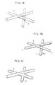
- FIG. 1A shows an enlarged view of its part.
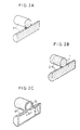
- Fig. 2A shows its joint portion.
- This unwoven fabric was heated at 300°C in the atmosphere for one hour to remove any low-temperature-volatile content in the binder. As a result, the content of binder decreased to 10.1 wt% of the entire unwoven fabric. Then, the fabric was heated at 650°C for one hour in N 2 gas.
- Fig. 1B shows its portion. The surface is seen to have irregularities 2.
- Fig. 2B shows its joint portion.
- the fabric obtained was cut to a 200 mm x 400 mm sheet.
- the sheet was immersed in a nickel plating bath shown in Fig. 1 and plated for 30 minutes while applying a current at a rate of 9.42 A/dm 2 to form a plating layer 3.
- Fig. 1C shows a portion of the fabric thus obtained.
- Carbon fabrics were prepared in the same manner as in Example 1 with different contents of epoxy resin as shown at Nos. 2-7 of Table 1. They were heated under the same conditions as in Example 1, and then plated with nickel. Table 1 shows the results of observations of these specimens. The specimens had different plating thicknesses from one another. This was accomplished by changing the plating time.
- An unwoven fabric 0.42 mm thick and 30 g/m 2 in weight per unit area was formed from carbon fibers 1 having a diameter of 7 ⁇ m, using an unsaturated polyester resin as a binder.
- the content of resin was 20 wt% of the entire fabric.
- This unwoven fabric was heated at 280°C in the atmosphere for 40 minutes to remove any low-temperature-volatile content in the binder until the content of binder decreases to 9.0 wt%. Then, the fabric was heated at 750°C for 40 minutes in N 2 gas.
- the material thus obtained was wound on a 200-mm-diameter roll, and passed through a plating bath for 25 minutes while applying a current at a rate of 11.3 A/dm 2 to form a nickel plating layer 3 shown in Fig. 1C by continuous plating.
- the fabric thus obtained was then roasted at 900°C for 10 minutes, and heated at 1000°C in H 2 gas to reduce its surface.
- An unwoven fabric made up of hollow metal fibers 3 shown in Fig. 2C was obtained.
- the interior of one metal fiber 3 communicates with that of another through an opening 5 at the joint portion.
- the diameter a of the opening 5 (gap width at joint) and the internal diameter b of the metal fibers 3 (gap diameter) are determined to satisfy the relation a/b > 0.5.
- Example 3 The same carbon fabrics as used in Example 3 were heated under different heating conditions shown in Table 2 at Nos. 9-20. They were then plated with nickel in the same manner as in Example 3. There were some specimens which could not be wound on rolls. Such specimens were cut to 200 mm x 400 mm sheets and plated in batches. These speciments were plated for 25 minutes while applying a current at a rate of 11.3 A/dm 2 . The results are shown at Nos. 9-20 in Table 2.
- Example 1 The same unwoven carbon fabric as used in Example 1 was heated in the same manner as in Example 1.
- the unplated unwoven fabric thus obtained was cut to 200 mm x 400 mm sheets, and the sheets were plated with nickel in the nickel bath shown in Table 1 under different plating conditions.
- Example 1 The same unwoven carbon fabric as used in Example 1 was heated in the same manner as in Example 1.
- the unplated unwoven fabric thus obtained was cut to a 200 mm x 400 mm sheet, and the sheet was plated with Cu in a bath (containing 200 g/l of CuSO 4 ⁇ 5H 2 O and 52 g/l of H 2 SO 4 ) kept at 30 ⁇ 2°C at a current of 2.0 A/dm 2 for 98 minutes.
- the Ag plating was formed in a bath containing 6 g/liter of AgCN and 110 g/liter of KCN kept at 25 ⁇ 2°C at a current of 5 A/dm 2 for 55 minutes.
- the Fe plating was formed in a bath containing 350 g/liter of FeSO4 (NH 4 ) 2 SO 4 ⁇ 6H 2 O and 120 g/liter of (NH 4 ) 2 SO 4 bath kept at 60°C ⁇ 2°C at a current of 8 A/dm 2 for 35 minutes.
- An unwoven fabric 1.3 mm thick and 50 g/m 2 in weight per unit area was formed from 13- ⁇ m-diameter carbon fibers 1, using an epoxy resin as a binder.
- the content of resin was 20 wt%.
- This unwoven fabric was heated at 300°C in the atmosphere for one hour to remove any low-temperature-volatile content in the binder. As a result, the content of binder decreased to 10.1 wt% of the entire unwoven fabric.
- the fabric was heated at 650°C for one hour in N 2 gas.
- the fabric obtained was cut to a 200 mm x 400 mm sheet.
- the sheet was immersed in a nickel plating bath shown in Table 1 and plated for 38 minutes while applying a current at rate of 9.42 A/dm 2 .
- the hollow portions of the metal fibers communicate with each other through openings formed at the joint portions of the fibers, so that the metal layer has a uniform thickness.
- Such a metal layer shows increased strength and high resistance to thermal stress.
- the method of the present invention electrical conductivity is given to the joint portions of the carbon fibers by carbonizing the binder resin.
- the carbon fibers and the binder resin are roughened finely.
- a plating layer can be formed directly on the unwoven carbon fabric thus formed by electroplating.
- the unwoven metal fabric made up of hollow metal fibers according to the present invention excels conventional metal fabrics of this type in its mechanical strength, porosity, surface area, distribution of fibers and weight.
- Gap width a / diameter b of hollow portions No Amount of binder after volatile removed (wt%) Electroplating Gap width a / diameter b of hollow portions Roughness at surface ( ⁇ m) Average Thickness ( ⁇ m) Gap width a at joint portions ( ⁇ m) 1 10.1 7 12.1 0.93 1.0 2 5.1 10 6.5 0.5 0.5 3 7.3 9 9.1 0.7 0.8 4 12.2 9 14.3 1.1 1.2 5 14.8 5 17.0 1.3 1.5 6 15.5 7 17.9 1.4 1.8 7 9.0 3 13.0 1.0 0.5 No Metal plated Plated State Gap width a / diameter b of hollow portions Porosity (%) Tensile Strength (kg/mm 2 ) Average Thickness ( ⁇ m) Roughness at surface ( ⁇ m) Gap width a at joint portions ( ⁇ m) 28 Cu 7.0 1.1 9.1 0.70 88 1.7 29 Ag 8.2 1.0 12.1 0.93 85 1.5 30 Fe 8.2 1.0 12.1 0.93 85 1.2 31 Ni 7.0 1.0 12.1 0.93
Landscapes
- Engineering & Computer Science (AREA)
- Textile Engineering (AREA)
- Chemical & Material Sciences (AREA)
- Inorganic Chemistry (AREA)
- Cell Electrode Carriers And Collectors (AREA)
- Electroplating Methods And Accessories (AREA)
- Nonwoven Fabrics (AREA)
Claims (8)
- Metall-Vliesstoff, bestehend aus einer Anhäufung von hohlen Metallfasern, die miteinander verbunden sind, wobei die hohlen Bereiche der Fasern an Verbindungsbereichen zwischen den Metallfasern miteinander in Verbindung stehen, dadurch gekennzeichnet, dass die Metallfasern auf ihren inneren und äußeren Oberflächen eine Rauheit von 0,5-1,5 µm haben.
- Metall-Vliesstoff nach Anspruch 1, bei dem der Bereich des Stoffes außer den Verbindungsbereichen eine durchschnittliche Metalldicke von 3-10 µm hat.
- Metall-Vliesstoff nach Anspruch 1 oder 2, bei dem er eine Porosität von 80 bis 98% hat.
- Metall-Vliesstoff nach einem der Ansprüche 1-3, bei dem die minimale Breite der Öffnung der Metallfasern an den Verbindungsbereichen nicht geringer ist als 50% des Durchmessers der hohlen Bereiche der Metallfasern.
- Metall-Vliesstoff nach einem der Ansprüche 1-4, bei dem die Metallfasern aus einem Element bestehen, welches auszuwählen ist aus einer Gruppe aus Ni, Cu, Ag und Fe.
- Verfahren zur Herstellung eines Metall-Vliesstoffes, bei welchem eine Vielzahl von Kohlenstoff-Fasern mittels eines Harzes miteinander verbunden werden, so dass ein Vliesstoff entsteht, bei welchem der Vliesstoff erwärmt wird, um das Harz zu karbonisieren und dem Harz Leitfähigkeit zu verleihen und sowohl die Oberfläche der Faser als auch die Oberfläche des Harzes aufzurauen, durch Elektroplattieren eine Metallschicht auf der Oberfläche des Stoffes und des Harzes gebildet wird, der Vliesstoff gebrannt wird, um die Kohlenstoff-Fasern zu entfernen, und der Vliesstoff in einer reduzierenden Atmosphäre reduziert wird, um die metallische Struktur zu verdichten, dadurch gekennzeichnet, dass bei dem Schritt des Erwärmens der Vliesstoff bei 200-350°C in der Atmosphäre erwärmt wird und dann in einer nichtoxidierenden Atmosphäre bei 500-850°C erwärmt wird, wobei das Erwärmen jeweils mindestens einmal stattfindet.
- Verfahren zur Herstellung eines Metall-Vliesstoffes nach Anspruch 6, bei dem die Kohlenstoff-Fasern, die den Kohlenstoff-Vliesstoff bilden, Fasern sind, die gebildet werden, indem Kohlenstoff-Fasern auf 750-900°C erwärmt werden.
- Verfahren zur Herstellung eines Metall-Vliesstoffes nach Anspruch 6 oder 7, bei dem die Kohlenstoff-Fasern, die den Kohlenstoff-Vliesstoff bilden, einen Durchmesser von 7-20 µm, eine Faserlänge von 3-20 mm und eine Packungsdichte von 2-20% haben.
Applications Claiming Priority (2)
| Application Number | Priority Date | Filing Date | Title |
|---|---|---|---|
| JP127508/94 | 1994-06-09 | ||
| JP12750894 | 1994-06-09 |
Publications (2)
| Publication Number | Publication Date |
|---|---|
| EP0686718A1 EP0686718A1 (de) | 1995-12-13 |
| EP0686718B1 true EP0686718B1 (de) | 1998-08-05 |
Family
ID=14961735
Family Applications (1)
| Application Number | Title | Priority Date | Filing Date |
|---|---|---|---|
| EP95108312A Expired - Lifetime EP0686718B1 (de) | 1994-06-09 | 1995-05-30 | Metall-Vliesstoff und Verfahren zur dessen Herstellung |
Country Status (2)
| Country | Link |
|---|---|
| EP (1) | EP0686718B1 (de) |
| DE (1) | DE69503845T2 (de) |
Families Citing this family (5)
| Publication number | Priority date | Publication date | Assignee | Title |
|---|---|---|---|---|
| JP3700312B2 (ja) * | 1996-04-19 | 2005-09-28 | 住友電気工業株式会社 | Fe金属多孔体の製造方法 |
| DE19910985B4 (de) * | 1999-03-12 | 2004-09-02 | Robert Bosch Gmbh | Verfahren zur Erzeugung metallischer Hohlfasern oder Hohlfaserstrukturen |
| EP1052321B1 (de) * | 1999-05-12 | 2008-08-27 | Sumitomo Electric Industries, Ltd. | Vliesstoff aus Metallfasern und Verfahren zu dessen Herstellung |
| DE102009057257A1 (de) | 2009-12-08 | 2011-06-09 | H.C. Starck Gmbh | Makroporöse Hohlkörper aus gesintertem Material, Verfahren zu deren Herstellung und Verwendung |
| DE102009057128A1 (de) | 2009-12-08 | 2011-06-09 | H.C. Starck Gmbh | Verfahren zur Herstellung von sintermetallischen Hohlkörpern, damit erhältliche Produkte und deren Verwendung |
Family Cites Families (5)
| Publication number | Priority date | Publication date | Assignee | Title |
|---|---|---|---|---|
| FR2558485B1 (fr) | 1984-01-25 | 1990-07-13 | Rech Applic Electrochimique | Structure metallique poreuse, son procede de fabrication et applications |
| US4999240A (en) * | 1986-07-21 | 1991-03-12 | Brotz Gregory R | Metalized fiber/member structures and methods of producing same |
| JP2678037B2 (ja) * | 1988-12-05 | 1997-11-17 | 日本精線株式会社 | 金属繊維フエルト状体及びその製造方法 |
| DE68925580T2 (de) * | 1989-04-14 | 1996-09-19 | Katayama Tokushu Kogyo Kk | Verfahren zur Herstellung einer porösen metallischen Folie |
| JPH0317957A (ja) | 1989-06-15 | 1991-01-25 | Kanai Jiyuuyou Kogyo Kk | ニッケルめっき不織布電極及びその製造方法 |
-
1995
- 1995-05-30 EP EP95108312A patent/EP0686718B1/de not_active Expired - Lifetime
- 1995-05-30 DE DE69503845T patent/DE69503845T2/de not_active Expired - Lifetime
Also Published As
| Publication number | Publication date |
|---|---|
| EP0686718A1 (de) | 1995-12-13 |
| DE69503845T2 (de) | 1999-04-29 |
| DE69503845D1 (de) | 1998-09-10 |
Similar Documents
| Publication | Publication Date | Title |
|---|---|---|
| US5643684A (en) | Unwoven metal fabric | |
| CA1068994A (en) | Assembly of metal-coated carbon fibers, process for producing thereof, and method for use thereof | |
| CA2166930C (en) | Process for preparing metallic porous body, electrode substrate for battery and process for preparing the same | |
| US5503941A (en) | Metal foam | |
| KR100209342B1 (ko) | 내식성 금속 다공질 부재의 제조방법 | |
| CN111902971B (zh) | 箔状功能材料及其制造方法 | |
| KR100247901B1 (ko) | Fe금속다공체의 제조방법 | |
| EP0404961B1 (de) | Vliesstoff aus metallfasern und verfahren zu dessen herstellung | |
| EP0686718A1 (de) | Metall-Vliesstoff und Verfahren zur dessen Herstellung | |
| EP0750360B1 (de) | Elektrodensubstrat für Batterie und Verfahren zu deren Herstellung | |
| US5100748A (en) | Structure of nickel hydroxide-based electrode doped with cobalt for an electrochemical generator | |
| JPH07258706A (ja) | 金属繊維焼結シートの製造方法 | |
| JPH08225865A (ja) | 三次元網状構造金属多孔体の製造方法 | |
| JPH0797602A (ja) | 異種金属被覆多孔性金属繊維焼結シートおよびその製造方法 | |
| EP1052321A1 (de) | Vliesstoff aus Metallfasern und Verfahren zu dessen Herstellung | |
| JPH08203534A (ja) | ニッケルめっき不織布電極基板の製造方法 | |
| DE19711857C2 (de) | Elektrodengerüst aus Nadelfilzmaterial | |
| JP3329329B2 (ja) | 金属不織布及びその製造方法 | |
| JP2971944B2 (ja) | 金属繊維不織布及びその製造方法 | |
| JP3736924B2 (ja) | 合金繊維フェルトマットの製造方法及び合金繊維フェルトマット及び繊維フェルトマットバーナ | |
| JPH08193232A (ja) | 金属多孔体の製造方法 | |
| HK1011462B (en) | Electrode substrate for battery and process for preparing the same | |
| JPH10204763A (ja) | ニッケル繊維フェルトマットの製造方法及びニッケル繊維フェルトマット | |
| JPH10131012A (ja) | 多孔質の金属シートおよびこれを用いた電池用の電極材 | |
| JPH08222226A (ja) | 三次元網状構造電極担体の製造方法 |
Legal Events
| Date | Code | Title | Description |
|---|---|---|---|
| PUAI | Public reference made under article 153(3) epc to a published international application that has entered the european phase |
Free format text: ORIGINAL CODE: 0009012 |
|
| AK | Designated contracting states |
Kind code of ref document: A1 Designated state(s): DE FR GB IT |
|
| 17P | Request for examination filed |
Effective date: 19960104 |
|
| 17Q | First examination report despatched |
Effective date: 19961206 |
|
| GRAG | Despatch of communication of intention to grant |
Free format text: ORIGINAL CODE: EPIDOS AGRA |
|
| GRAG | Despatch of communication of intention to grant |
Free format text: ORIGINAL CODE: EPIDOS AGRA |
|
| GRAH | Despatch of communication of intention to grant a patent |
Free format text: ORIGINAL CODE: EPIDOS IGRA |
|
| GRAH | Despatch of communication of intention to grant a patent |
Free format text: ORIGINAL CODE: EPIDOS IGRA |
|
| GRAA | (expected) grant |
Free format text: ORIGINAL CODE: 0009210 |
|
| AK | Designated contracting states |
Kind code of ref document: B1 Designated state(s): DE FR GB IT |
|
| REF | Corresponds to: |
Ref document number: 69503845 Country of ref document: DE Date of ref document: 19980910 |
|
| ET | Fr: translation filed | ||
| PLBE | No opposition filed within time limit |
Free format text: ORIGINAL CODE: 0009261 |
|
| STAA | Information on the status of an ep patent application or granted ep patent |
Free format text: STATUS: NO OPPOSITION FILED WITHIN TIME LIMIT |
|
| 26N | No opposition filed | ||
| REG | Reference to a national code |
Ref country code: GB Ref legal event code: IF02 |
|
| REG | Reference to a national code |
Ref country code: GB Ref legal event code: 746 Effective date: 20040728 |
|
| REG | Reference to a national code |
Ref country code: FR Ref legal event code: D6 |
|
| REG | Reference to a national code |
Ref country code: FR Ref legal event code: ST Effective date: 20090119 |
|
| PG25 | Lapsed in a contracting state [announced via postgrant information from national office to epo] |
Ref country code: FR Free format text: LAPSE BECAUSE OF NON-PAYMENT OF DUE FEES Effective date: 20080602 |
|
| REG | Reference to a national code |
Ref country code: FR Ref legal event code: D3 |
|
| PGFP | Annual fee paid to national office [announced via postgrant information from national office to epo] |
Ref country code: GB Payment date: 20100329 Year of fee payment: 16 |
|
| PGFP | Annual fee paid to national office [announced via postgrant information from national office to epo] |
Ref country code: FR Payment date: 20100525 Year of fee payment: 16 |
|
| PGFP | Annual fee paid to national office [announced via postgrant information from national office to epo] |
Ref country code: DE Payment date: 20100526 Year of fee payment: 16 |
|
| PGFP | Annual fee paid to national office [announced via postgrant information from national office to epo] |
Ref country code: IT Payment date: 20100521 Year of fee payment: 16 |
|
| REG | Reference to a national code |
Ref country code: DE Ref legal event code: R119 Ref document number: 69503845 Country of ref document: DE |
|
| REG | Reference to a national code |
Ref country code: DE Ref legal event code: R119 Ref document number: 69503845 Country of ref document: DE |
|
| GBPC | Gb: european patent ceased through non-payment of renewal fee |
Effective date: 20110530 |
|
| REG | Reference to a national code |
Ref country code: FR Ref legal event code: ST Effective date: 20120131 |
|
| PG25 | Lapsed in a contracting state [announced via postgrant information from national office to epo] |
Ref country code: IT Free format text: LAPSE BECAUSE OF NON-PAYMENT OF DUE FEES Effective date: 20110530 |
|
| PG25 | Lapsed in a contracting state [announced via postgrant information from national office to epo] |
Ref country code: FR Free format text: LAPSE BECAUSE OF NON-PAYMENT OF DUE FEES Effective date: 20110531 |
|
| PG25 | Lapsed in a contracting state [announced via postgrant information from national office to epo] |
Ref country code: GB Free format text: LAPSE BECAUSE OF NON-PAYMENT OF DUE FEES Effective date: 20110530 |
|
| PG25 | Lapsed in a contracting state [announced via postgrant information from national office to epo] |
Ref country code: DE Free format text: LAPSE BECAUSE OF NON-PAYMENT OF DUE FEES Effective date: 20111130 |