EP0686737B1 - Installation de pose de panneaux sans fixation visible, notamment pour l'habillage de murs et/ou la mise en place d'étagères ou d'équipements suspendus et outil pour la mise en place d'une telle installation - Google Patents
Installation de pose de panneaux sans fixation visible, notamment pour l'habillage de murs et/ou la mise en place d'étagères ou d'équipements suspendus et outil pour la mise en place d'une telle installation Download PDFInfo
- Publication number
- EP0686737B1 EP0686737B1 EP95401279A EP95401279A EP0686737B1 EP 0686737 B1 EP0686737 B1 EP 0686737B1 EP 95401279 A EP95401279 A EP 95401279A EP 95401279 A EP95401279 A EP 95401279A EP 0686737 B1 EP0686737 B1 EP 0686737B1
- Authority
- EP
- European Patent Office
- Prior art keywords
- support
- panels
- branch
- racks
- rack
- Prior art date
- Legal status (The legal status is an assumption and is not a legal conclusion. Google has not performed a legal analysis and makes no representation as to the accuracy of the status listed.)
- Expired - Lifetime
Links
- 239000000725 suspension Substances 0.000 title claims 4
- 238000009434 installation Methods 0.000 title description 36
- 238000001125 extrusion Methods 0.000 abstract 1
- 230000001788 irregular Effects 0.000 description 5
- 238000000034 method Methods 0.000 description 4
- 238000005253 cladding Methods 0.000 description 3
- 210000000056 organ Anatomy 0.000 description 3
- 230000004308 accommodation Effects 0.000 description 2
- 238000005034 decoration Methods 0.000 description 2
- 239000003292 glue Substances 0.000 description 2
- 239000000463 material Substances 0.000 description 2
- 238000005728 strengthening Methods 0.000 description 2
- 239000000853 adhesive Substances 0.000 description 1
- 238000004026 adhesive bonding Methods 0.000 description 1
- 230000001070 adhesive effect Effects 0.000 description 1
- 239000011324 bead Substances 0.000 description 1
- 239000011248 coating agent Substances 0.000 description 1
- 238000000576 coating method Methods 0.000 description 1
- 238000005520 cutting process Methods 0.000 description 1
- 230000007547 defect Effects 0.000 description 1
- 230000000694 effects Effects 0.000 description 1
- 238000010616 electrical installation Methods 0.000 description 1
- 239000011521 glass Substances 0.000 description 1
- 239000011229 interlayer Substances 0.000 description 1
- 238000005304 joining Methods 0.000 description 1
- 238000003754 machining Methods 0.000 description 1
- 230000000717 retained effect Effects 0.000 description 1
Images



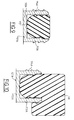
Classifications
-
- E—FIXED CONSTRUCTIONS
- E04—BUILDING
- E04F—FINISHING WORK ON BUILDINGS, e.g. STAIRS, FLOORS
- E04F19/00—Other details of constructional parts for finishing work on buildings
- E04F19/02—Borders; Finishing strips, e.g. beadings; Light coves
- E04F19/06—Borders; Finishing strips, e.g. beadings; Light coves specially designed for securing panels or masking the edges of wall- or floor-covering elements
- E04F19/062—Borders; Finishing strips, e.g. beadings; Light coves specially designed for securing panels or masking the edges of wall- or floor-covering elements used between similar elements
Definitions
- the present invention relates to an installation for installing panels without visible fixing for covering of walls and the installation of shelves or equipment suspended, according to the preamble of claim 1.
- a such an installation is already known.
- Wall claddings and in particular equipment stores are increasingly made up of rack systems, receiving consoles for carry shelves or display boxes. These racks can also receive hooks for hanging articles to present.
- the interval between two racks is covered by a panel constituting a decoration bottom or a panel for example perforated, allowing to receive hooks or presentation supports.
- the panels are placed between the racks and do not overflow on them. In other cases, these panels partially cover the racks leaving only a slot just sufficient to place the brackets or brackets supporting the shelves or presentation equipment.
- the panels are placed freely between the profiles and are held in place by keys or organs holding hooks in the rack and having tabs protruding from the front of the panels for retain them.
- the object of the present invention is to remedy these disadvantages and proposes to create an installation for installing panels without visible fixing for covering of walls and / or the installation of shelves or equipment hanging or presentation, composed of profiles or racks receiving the panels or / and the shelves or equipment via brackets, brackets or hooks, and which are particularly suitable for placement simple while offering ongoing aesthetics, removing irregular joints between panels or profiles, and allowing to install in a particularly simple not only the panels but also profiles with perfect parallelism to panels.
- the invention relates to an installation of the type defined above, according to the first claim.
- the panels are mounted by simple pressure without fixing device surface and the edges of the panels can thus be precisely adapted either to the width of the part central rack, only at the necessary width the passage of the consoles, the racks being then hidden themselves or with adjoining panels.
- This installation is done precisely, without it no need to allow clearance between the panels and / or the racks, game made necessary in the techniques because of the relative imprecision of the installation of racks.
- the panel being rigid, it holds the racks which remain thus naturally parallel and at the appropriate spacing.
- the assembly thus formed can be put in place on a support such as a wall, even if this support is more or less regular. We can thus fix the racks by placing the shims in the right place without occasionally of the installation, the racks are not deformed by pulling in or out bumps.
- This setup is much easier that setting up racks using rules and bubble levels to ensure parallelism and the straightness of the racks on the support.
- the installation rack and pinion is done using the above principle but by iterating from a first rack installed on the support.
- This first rack then receives a first panel whose edge intended at this rack is provided with supporting parts and the other edge of which carries the supporting parts themselves the second rack.
- the link between the rack and the panel can be done using appropriate tools, allowing removable mounting without having to fix the pieces from the start support.
- the invention thus makes it possible to easily carry out a rack and span installation or of identical or variable widths as required of the room to be equipped or aesthetic intentions.
- Installation panels are easily removable which allows to modify the decoration of installing or replacing smooth panels with example with hole panels used to receive accessories presentation or others.
- Another possibility is to replace some panels with glass to which the supporting parts.
- covers or installations for shelves, displays or the like can be disassembled and reassemble without damaging the panels.
- Another advantage of the invention is to simplify considerably work on site and allow a perfect finish. Indeed like the interval panels or racks is obtained from panels and not the reverse as in the prior art, it is easy to fix the supporting parts on the panels so that these are perfectly joined together or to the racks and this starting from panels cut in workshop without requiring machining. This in turn makes unnecessary any adjustments to the edges of the panel to be made on site, as was necessary according to known techniques, especially since such interventions require great care in their execution for not to damage the visible face of the panels which when the coating is fragile, risk of chipping. On the contrary, as according to the invention, the panels are prepared in the workshop, this panel cutting work can be done with all the precision and care necessary.
- the branch main and side branch have teeth and parts support have notches in homologous positions to those of the teeth of the main branch and the branch lateral.
- the piece support consists of a main part coming in the housing of the profile and of a lateral part forming with the main part a groove to cover the lateral branch.
- each lateral branch of the rack has teeth on the outside and side of the support piece has notches in a position homologous to that of the teeth.
- FIGS 1 to 3 show schematically the structure of an installation for hanging shelves or hanging equipment in two variants of installation, known which will be described below in using the figures to better explain this prior art.
- the installation consists of racks 1 fixed to a support 2 such as a wall by connecting means such as peg screws 4, 5.
- racks 1 are intended to receive cladding or support panels 6, 7 retained to rack 1 by hooking pieces in shape of keys 8.
- the rack 1 is consists of a central part 11 connected by branches of support 12 to lateral branches 13, raised.
- the part central consists of two main branches 14 connected in the upper part by a cross member 15.
- This cross member 15 is provided with holes 16 in the form of holes, for example rectangular used to receive consoles carrying the shelves or other displays as well as the keys 8 retaining the panels 6.
- the support branches 12 which border each side the central part 11 by being connected to the branches main 14, have holes for the passage of fixing screw 4. These support branches are terminated by the lateral branches 13, raised serving to support the panels 6.
- the key 8 ( Figure 2) retaining the panels 6 is consists of a plate 81, coming in front of panels 6 and a perpendicular branch 82 provided with a cutout 83 to hang in the holes 16 of the central part 11 of rack 1.
- FIG. 3 stands out from that of FIG. 1 in that the panels 7 comprise a rebate 71 which allows the panels to style the front end of the central part 11, the edges in look at the panels 7 leaving only a corresponding interval substantially to the thickness of the branch 82 of the key and which also corresponds to the thickness of the consoles or brackets.
- a rebate 71 which allows the panels to style the front end of the central part 11, the edges in look at the panels 7 leaving only a corresponding interval substantially to the thickness of the branch 82 of the key and which also corresponds to the thickness of the consoles or brackets.
- the key 8 of the example in Figure 3 has a notch 83 placed so to take into account the extra thickness of the panels 7 by relative to the front face of the central part 11 of the rack 1.
- FIG. 4 to 8 Installation of panels without fixing visible, especially for wall cladding and / or installation of shelves or hanging equipment and tool for the installation of such an installation shelves or hanging equipment according to the present invention as shown in Figures 4 to 8 consists also omega 101 racks attached to a support 102 an example of which is shown in section on the figure 4.
- These racks include a central part 111 formed by two main branches 114 and a cross 115 provided with orifices 116 receiving the consoles or brackets.
- the main part is bordered by side parts also formed of support legs 112 and terminated by raised branches 113.
- a main branch 114, the supporting branch 112 and the corresponding lateral branch 113 delimit a housing 117 intended to receive an organ 120 or 130 support ( Figures 5, 6).
- the main branch 114 has a tooth 118 and the lateral branch 113 has two teeth 118 turned inward.
- This branch also includes three teeth 118 on the outside, for the reasons that will appear later.
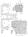
- the part support 120 ( Figure 5) is a piece of material having a certain elasticity, corresponding for example to a hardness shore 70, and cut in a cord or bar of a such material.
- This support piece has a rectangular section with a bearing face 121, two lateral faces 122 and a bottom 123 connected to the lateral faces by parts rounded 124. Finally, on the sides 122 there are notches 125 in positions homologous to teeth 118 of housing 117.
- This support piece 120 is placed in the housing 117 as shown in Figures 7 and 8.
- the bearing surface 121 is intended to be glued on the back of a panel 106 or 107 ( Figures 7 and 8).
- Figure 6 shows the section of another mode for producing a support piece 130 formed from a part main 141 and a lateral part 151 joined according to plan XX.
- the main part 141 corresponds to the section of the part 120 but extended in the direction of the height.
- Between the two parts 141, 151 we formed a throat 131.
- the main piece 130 has, for its main part 141 a shape similar to that of the support piece 120: its lateral faces 142, 143 are flat, as is its front face 144, with rounded parts 145 at the junction.
- this part 141 has a height substantially equal to that of the main branch 114 of the rack so that its bearing face 146 either at the level of the front face of the branches 114 of the rack and allow the installation of the panels 107 shown in Figure 8.
- Part 141 be reduced, depending on the panel thickness and the height difference between the branches 114 and 113.
- the side faces 142, 143 are provided with notches 147 in positions homologous to the teeth 118 of branches 114, 113.
- the lateral part 151 has lateral faces 152, 153 planes, one front face 154, joined to the side faces by rounding 155 and a bearing face 156 in the alignment of the face 146.
- the face 152 is provided with a notch 159.
- the lateral part 151 has a lower height to that of the main part 141.
- room 130 comes to the bottom of the housing 117 bearing by its face 144 against the branch support 112 so as to precisely define the level of the bearing surface (146, 156) and consequently the level of the sign.
- This part 130 is put in place, for the part main 141, like room 120, side 151 overlapping with the throat 131 the lateral branch 113.
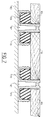
- Figure 7 is a section showing the implementation place of panels 106 on racks 101 fixed to a support 102 such as a wall.
- the panels leave the racks 101 accessible to the consoles or hooks not shown, the panels using the parts support 120.
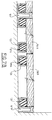
- Figure 7A shows a variant for panels 106 'of relatively large width between the racks 101 and requiring to arrive at a flatness perfect that the panel 106 'is supported.
- a 101A profile whose cross section corresponds to a part of section 101 to receive parts support 120.
- This profile consists of branch 113 (113A) of the support branch 112A corresponding to the branch 112 and branch 114A corresponding to part of main branch 114.
- FIG. 7B corresponds to edge-to-edge assembly of two panels 106A, 106B with support on a section 101A as in FIG. 7A, with support pieces 120.
- This figure also shows another special part, for a corner: part 101B of the profile 101 having kept the crosspiece with the orifices forming the rack.
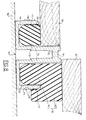
- Figure 8 shows the two implementation cases places panels 106 and 107 using support pieces 120 or 130 depending on whether you want to leave visible the whole front face of the central part 111 or only a slot for setting up consoles.
- Figure 9 shows the section of a section 101A as described above, with a support piece 120.
- Figure 10 shows a section 101A receiving a support piece 130.
- the panels, the supporting parts and the racks are installed either by placing the racks first and then putting the supporting parts in the housings of the racks, in gluing them and placing the panels on the surfaces supporting the parts, and keeping the assembly tightened by example using a tool like the one in Figures 11 and 12.
- the panel is used as a template mounting racks to ensure alignment precise in difficult cases (irregular supports) or when the panels must be perfectly aligned on the edges of the central parts of the racks.
- we set up the assembly formed by a panel including a edge is provided with supporting parts and the other edge is provided with supporting parts themselves carrying a rack.
Landscapes
- Engineering & Computer Science (AREA)
- Architecture (AREA)
- Civil Engineering (AREA)
- Structural Engineering (AREA)
- Connection Of Plates (AREA)
- Assembled Shelves (AREA)
- Display Racks (AREA)
- Supports Or Holders For Household Use (AREA)
Description
- la partie latérale est moins longue que la partie principale.
- la pièce d'appui a, en partie avant, des arêtes arrondies.
- la pièce d'appui est coupée à la longueur dans un cordon profilé.
- la figure 1 est une coupe transversale d'une installation connue, au niveau d'une crémaillère et de deux panneaux réunis sur la crémaillère.
- la figure 2 est une vue en perspective d'une clef de fixation de panneau connue.
- la figure 3 est une vue en coupe analogue à la figure 1 montrant une autre mise en place de panneaux sur des crémaillères connues.
- la figure 4 est une vue en coupe d'une crémaillère selon l'invention.
- la figure 5 est une vue en coupe d'un premier mode de réalisation de pièces d'appui selon l'invention.
- la figure 6 est une vue en coupe d'une autre pièce d'appui selon l'invention.
- la figure 7 est une vue en coupe transversale d'une installation selon l'invention, montrant des crémaillères et des panneaux fixés aux crémaillères.
- les figures 7A et 7B montrent deux variantes, la première pour un panneau de grande largeur et la seconde pour la jonction de deux panneaux bord à bord.
- la figure 8 montre, à une échelle différente de la figure 7, deux modes possibles de mise en place de panneaux sur une crémaillère.
- la figure 9 est une vue en coupe d'un profilé intermédiaire de faible hauteur.
- la figure 10 est une vue en coupe d'un profilé de hauteur importante pour une pièce d'appui à gorge selon la figure 6.
Claims (7)
- Installation de pose de panneaux sans fixation visible pour l'habillage de murs et pour l'accrochage de consoles ou de crochets recevant des étagères ou un équipement suspendu, ladite installation comprenantinstallation caractérisée en ce qu'elle comprend :des crémaillères (101) en forme de profilés, destinées à être fixées à un support (102) tel qu'un mur ou un meuble, chaque crémaillère (101) ayant des orifices (116) pour l'accrochage de consoles ou de crochets recevant des étagères ou un équipement suspendu,chaque crémaillère (101) ayant une section en forme d'oméga, avec une partie centrale (111) munie des orifices d'accrochage (116), formée par deux branches (114) reliées par une traverse (115), cette partie centrale (111) étant bordée par au moins une partie latérale comprenant une branche d'appui (112) et une branche latérale (113), relevée, chaque crémaillère (101) étant destinée à être fixée au support (102) au niveau des branches d'appui (112), les branches latérales (113) formant une butée pour les panneaux (106, 107) d'habillage ou de présentation destinés à être placés entre les crémaillères (101),des pièces d'appui (120, 130) destinées à être reliées solidairement aux panneaux (106, 107) pour s'engager élastiquement et de manière amovible dans les logements (117, 117) formés dans les crémaillères (101) entre chaque branche principale (114), la branche latérale (113) et la branche d'appui (112),ces pièces d'appui (120, 130) ayant une section correspondant à celle du logement (117, 117),la hauteur des pièces d'appui (120, 130) étant choisie en fonction du niveau souhaité pour la face avant du panneau (106, 107) par rapport à la crémaillère (101).
- Installation selon la revendication 1,
caractérisée en ce quela branche principale (114) et la branche latérale (113) ont des dents (118) et les pièces d'appui (120, 130) ont des encoches (125, 147, 159) dans des positions homologues à celles des dents (118) de la branche principale (114) et de la branche latérale (113). - Installation selon la revendication 1,
caractérisée en ce quela pièce d'appui (130) se compose d'une partie principale (141) venant dans le logement (117) du profilé (101) et d'une partie latérale (151) formant avec la partie principale une gorge (131) pour coiffer la branche latérale (113). - Installation selon la revendication 3,
caractérisée en ce quechaque branche latérale (113) de la crémaillère comporte des dents (118) sur la face extérieure et la partie latérale (151) de la pièce d'appui (130) comporte des encoches (159) dans une position homologue à celle des dents (118). - Installation selon la revendication 3,
caractérisée en ce quela partie latérale (151) est moins haute que la partie principale (141). - Installation selon la revendication 1,
caractérisée en ce quela pièce d'appui (120, 130) a, en partie avant, des arêtes arrondies (124, 145, 155). - Installation selon la revendication 1,
caractérisée en ce quela pièce d'appui (120, 130) est coupée à la longueur dans un cordon profilé.
Applications Claiming Priority (2)
| Application Number | Priority Date | Filing Date | Title |
|---|---|---|---|
| FR9407136A FR2721053B1 (fr) | 1994-06-10 | 1994-06-10 | Installation de pose de panneaux sans fixation visible, notamment pour l'habillage de murs et/ou la mise en place d'étagères ou d'équipements suspendus et outil pour la mise en place d'une telle installation. |
| FR9407136 | 1994-06-10 |
Publications (2)
| Publication Number | Publication Date |
|---|---|
| EP0686737A1 EP0686737A1 (fr) | 1995-12-13 |
| EP0686737B1 true EP0686737B1 (fr) | 1999-12-22 |
Family
ID=9464096
Family Applications (1)
| Application Number | Title | Priority Date | Filing Date |
|---|---|---|---|
| EP95401279A Expired - Lifetime EP0686737B1 (fr) | 1994-06-10 | 1995-06-01 | Installation de pose de panneaux sans fixation visible, notamment pour l'habillage de murs et/ou la mise en place d'étagères ou d'équipements suspendus et outil pour la mise en place d'une telle installation |
Country Status (8)
| Country | Link |
|---|---|
| US (1) | US5638653A (fr) |
| EP (1) | EP0686737B1 (fr) |
| AT (1) | ATE188002T1 (fr) |
| CA (1) | CA2151449A1 (fr) |
| DE (1) | DE69514041T2 (fr) |
| ES (1) | ES2143016T3 (fr) |
| FR (1) | FR2721053B1 (fr) |
| PT (1) | PT686737E (fr) |
Families Citing this family (25)
| Publication number | Priority date | Publication date | Assignee | Title |
|---|---|---|---|---|
| US20030084634A1 (en) | 2001-11-08 | 2003-05-08 | Oliver Stanchfield | Transition molding |
| US6223485B1 (en) | 1996-06-07 | 2001-05-01 | Herman Miller, Inc. | Wall panel system |
| US6167665B1 (en) | 1996-06-07 | 2001-01-02 | Herman Miller, Inc. | Corner post for a wall panel system |
| AUPO291296A0 (en) * | 1996-10-11 | 1996-11-07 | Rudduck, Dickory | Building elements |
| DE29800664U1 (de) * | 1997-01-17 | 1998-04-16 | Lech Jerzy | Fassadenbekleidung mit Fassadenplatten |
| DE19855834A1 (de) * | 1998-12-03 | 2000-06-21 | Gustav Kerle | Vorrichtung zur Bekleidung von Wänden, Platten oder dergleichen mit flächigen Teilen |
| GB2353541B (en) | 1999-06-04 | 2003-10-15 | Miller Herman Inc | Stackable wall panel system |
| US6295764B1 (en) | 1999-06-04 | 2001-10-02 | Herman Miller, Inc. | Stackable wall panel system |
| US6729085B2 (en) | 2001-02-09 | 2004-05-04 | Herman Miller, Inc. | Wall panel system |
| CA2449956C (fr) * | 2001-06-07 | 2009-06-02 | Telezygology Inc. | Dispositif de reglage et element de construction |
| US7207143B2 (en) | 2001-11-08 | 2007-04-24 | Pergo (Europe) Ab | Transition molding and installation methods therefor |
| DE50210994D1 (de) * | 2001-11-28 | 2007-11-08 | Meyer Hans | Verlegesystem für bodenplatten |
| US6862855B1 (en) * | 2003-04-16 | 2005-03-08 | Dave G. Milum | Structural assembly for decks, walkways, patios, and docks |
| AT505453B1 (de) * | 2004-02-27 | 2009-07-15 | Neuhofer Franz Jun | Abdeckvorrichtung für fussbodenbeläge |
| AT500734B1 (de) * | 2004-02-27 | 2009-10-15 | Neuhofer Franz Jun | Vorrichtung zum überbrücken eines höhenunterschiedes zwischen zwei fussbodenflächen |
| US7389614B2 (en) * | 2004-05-18 | 2008-06-24 | Sullivan Andrew P | Attic storage system |
| FR2885922B1 (fr) * | 2005-05-23 | 2007-08-10 | Quinn Plastics France Sa Sa | Profile pour la fixation de panneaux en vue de la realisation d'une paroi |
| ZA200608862B (en) * | 2005-10-31 | 2008-03-26 | Lafarge Gypsum Pty Ltd | Drywalls joint |
| EP2076638A4 (fr) * | 2006-10-18 | 2011-05-11 | Pergo AG | Joints ayant des surfaces disparates |
| CA2697573A1 (fr) * | 2009-03-27 | 2010-09-27 | Pergo (Europe) Ab | Ensemble de recouvrement de joints, trousse comprenant cet ensemble et procede d'installation connexe |
| US20100001247A1 (en) * | 2009-09-18 | 2010-01-07 | Luis Jaimes | Barrier Post and System |
| US8745950B2 (en) * | 2011-02-10 | 2014-06-10 | Nichiha Corporation | Construction structure of wall surface |
| CA2866534C (fr) * | 2014-10-06 | 2020-10-06 | Stephane Lafontaine Berger | Plateforme |
| AU201716954S (en) * | 2017-11-15 | 2017-12-18 | Glamagard Pty Ltd | Extrusion |
| US11206926B1 (en) * | 2020-05-13 | 2021-12-28 | David W Moeller | Truss-mounted attic storage system |
Family Cites Families (6)
| Publication number | Priority date | Publication date | Assignee | Title |
|---|---|---|---|---|
| DE2966399D1 (en) * | 1979-06-08 | 1983-12-15 | Charles Reith | Double u-section upright with openings |
| EP0107739B1 (fr) * | 1982-10-28 | 1986-08-27 | The Columbus Show Case Company | Mur-rideau |
| DE8401923U1 (de) * | 1984-01-24 | 1984-04-19 | Agrob-Wessel-Servais AG, 5305 Alfter | Einrichtung zur verkleidung von flaechen mit flaechenelementen |
| US4625477A (en) * | 1985-12-13 | 1986-12-02 | Masonite Corporation | Display wall formed of readily attachable and detachable panels |
| US5263292A (en) * | 1991-01-07 | 1993-11-23 | American Wall Products | Building panel system |
| US5185971A (en) * | 1991-05-17 | 1993-02-16 | Johnson Jr Hugh L | Channeled wall panel |
-
1994
- 1994-06-10 FR FR9407136A patent/FR2721053B1/fr not_active Expired - Lifetime
-
1995
- 1995-06-01 ES ES95401279T patent/ES2143016T3/es not_active Expired - Lifetime
- 1995-06-01 DE DE69514041T patent/DE69514041T2/de not_active Expired - Fee Related
- 1995-06-01 PT PT95401279T patent/PT686737E/pt unknown
- 1995-06-01 EP EP95401279A patent/EP0686737B1/fr not_active Expired - Lifetime
- 1995-06-01 AT AT95401279T patent/ATE188002T1/de not_active IP Right Cessation
- 1995-06-06 US US08/468,796 patent/US5638653A/en not_active Expired - Fee Related
- 1995-06-09 CA CA002151449A patent/CA2151449A1/fr not_active Abandoned
Also Published As
| Publication number | Publication date |
|---|---|
| DE69514041T2 (de) | 2000-09-14 |
| FR2721053B1 (fr) | 1996-08-02 |
| PT686737E (pt) | 2000-06-30 |
| CA2151449A1 (fr) | 1995-12-11 |
| ATE188002T1 (de) | 2000-01-15 |
| EP0686737A1 (fr) | 1995-12-13 |
| FR2721053A1 (fr) | 1995-12-15 |
| DE69514041D1 (de) | 2000-01-27 |
| ES2143016T3 (es) | 2000-05-01 |
| US5638653A (en) | 1997-06-17 |
Similar Documents
| Publication | Publication Date | Title |
|---|---|---|
| EP0686737A1 (fr) | Installation de pose de panneaux sans fixation visible, notamment pour l'habillage de murs et/ou la mise en place d'étagères ou d'equipements suspendus et outil pour la mise en place d'une telle installation | |
| EP2486195B1 (fr) | Ossature pour fixation de panneaux formant paroi murale ou cloison | |
| FR2697274A1 (fr) | Revêtement de mur avec système de support. | |
| FR2737264A1 (fr) | Dispositif d'accrochage invisible pour panneaux ou plaques de parement et systeme d'agencement interieur en faisant application | |
| FR2968026A1 (fr) | Systeme de panneaux de plafond | |
| FR2789862A3 (fr) | Structure de paroi comportant un rail profile insere servant a l'accrochage de bras de support destines a la suspension directe ou indirecte d'articles | |
| EP0438951B1 (fr) | Cloison modulaire destinée à construire des locaux | |
| WO2006106233A1 (fr) | Revetement de sol modulaire a dalles encadrees a demontage individuel des modules d'encadrement | |
| BE1008571A3 (fr) | Equipement a lamelles notamment a lamelles metalliques, pour des lambris agrafes formant des surfaces d'habillage. | |
| FR2843414A1 (fr) | Dispositif d'assemblage amovible d'elements plats constituant une surface plane | |
| EP0212996B1 (fr) | Ensemble d'éléments pour l'agencement de salles d'exposition, de magasins et autres lieux | |
| FR3137932A1 (fr) | Panneau modulaire à structure légère et cloison réalisée avec de tels panneaux modulaires | |
| EP2453540B1 (fr) | Rail de support universel | |
| FR2664633A1 (fr) | Plafond suspendu. | |
| FR2724987A1 (fr) | Systeme d'accrochage d'elements d'amenagement a une paroi | |
| FR2522044A1 (fr) | Profile pour la realisation de cloisons amovibles et systeme de cloison utilisant ce profile | |
| EP4647567A1 (fr) | Caillebotis pour piscine, équipement pour piscine et procédé d'installation | |
| FR2874162A1 (fr) | Presentoir pour produits destines a la vente | |
| FR3002561A1 (fr) | Ensemble de cloison, connecteur et semelle de cet ensemble de cloison, kit pour cet ensemble de cloison et procede de pose d’un gabarit de support de cet ensemble de cloison | |
| FR3082542A1 (fr) | Procede de realisation d'un parement | |
| FR2988753A1 (fr) | Dispositif de montage et de fixation de panneaux de revetement | |
| FR2898788A1 (fr) | Montant profile pour la realisation de mobilier de presentation de produit et mobilier obtenu a partir d'un tel montant profile | |
| FR2697273A1 (fr) | Dispositif de fixation et de pose de lattes pour constituer des plafonds ou sous-bassements, ou habillages de plafonds et de murs verticaux. | |
| WO2024261411A1 (fr) | Panneau modulaire à structure légère et cloison realisée avec de tels panneaux modulaires | |
| FR3133211A1 (fr) | Menuiserie équipée d’un volet roulant accessible de l’intérieur |
Legal Events
| Date | Code | Title | Description |
|---|---|---|---|
| PUAI | Public reference made under article 153(3) epc to a published international application that has entered the european phase |
Free format text: ORIGINAL CODE: 0009012 |
|
| AK | Designated contracting states |
Kind code of ref document: A1 Designated state(s): AT BE CH DE DK ES GB GR IE IT LI LU MC NL PT SE |
|
| 17P | Request for examination filed |
Effective date: 19960427 |
|
| 17Q | First examination report despatched |
Effective date: 19980327 |
|
| GRAG | Despatch of communication of intention to grant |
Free format text: ORIGINAL CODE: EPIDOS AGRA |
|
| GRAG | Despatch of communication of intention to grant |
Free format text: ORIGINAL CODE: EPIDOS AGRA |
|
| GRAH | Despatch of communication of intention to grant a patent |
Free format text: ORIGINAL CODE: EPIDOS IGRA |
|
| GRAH | Despatch of communication of intention to grant a patent |
Free format text: ORIGINAL CODE: EPIDOS IGRA |
|
| GRAA | (expected) grant |
Free format text: ORIGINAL CODE: 0009210 |
|
| AK | Designated contracting states |
Kind code of ref document: B1 Designated state(s): AT BE CH DE DK ES GB GR IE IT LI LU MC NL PT SE |
|
| PG25 | Lapsed in a contracting state [announced via postgrant information from national office to epo] |
Ref country code: GR Free format text: LAPSE BECAUSE OF NON-PAYMENT OF DUE FEES Effective date: 19991222 Ref country code: AT Free format text: LAPSE BECAUSE OF FAILURE TO SUBMIT A TRANSLATION OF THE DESCRIPTION OR TO PAY THE FEE WITHIN THE PRESCRIBED TIME-LIMIT Effective date: 19991222 |
|
| REF | Corresponds to: |
Ref document number: 188002 Country of ref document: AT Date of ref document: 20000115 Kind code of ref document: T |
|
| RIN1 | Information on inventor provided before grant (corrected) |
Inventor name: ROSSI, ROLAND |
|
| REG | Reference to a national code |
Ref country code: CH Ref legal event code: EP |
|
| REF | Corresponds to: |
Ref document number: 69514041 Country of ref document: DE Date of ref document: 20000127 |
|
| REG | Reference to a national code |
Ref country code: IE Ref legal event code: FG4D Free format text: FRENCH |
|
| ITF | It: translation for a ep patent filed | ||
| PG25 | Lapsed in a contracting state [announced via postgrant information from national office to epo] |
Ref country code: DK Free format text: LAPSE BECAUSE OF FAILURE TO SUBMIT A TRANSLATION OF THE DESCRIPTION OR TO PAY THE FEE WITHIN THE PRESCRIBED TIME-LIMIT Effective date: 20000322 |
|
| GBT | Gb: translation of ep patent filed (gb section 77(6)(a)/1977) |
Effective date: 20000322 |
|
| REG | Reference to a national code |
Ref country code: CH Ref legal event code: NV Representative=s name: SCHMAUDER & PARTNER AG PATENTANWALTSBUERO |
|
| REG | Reference to a national code |
Ref country code: ES Ref legal event code: FG2A Ref document number: 2143016 Country of ref document: ES Kind code of ref document: T3 |
|
| PG25 | Lapsed in a contracting state [announced via postgrant information from national office to epo] |
Ref country code: LU Free format text: LAPSE BECAUSE OF NON-PAYMENT OF DUE FEES Effective date: 20000601 |
|
| REG | Reference to a national code |
Ref country code: PT Ref legal event code: SC4A Free format text: AVAILABILITY OF NATIONAL TRANSLATION Effective date: 20000321 |
|
| PG25 | Lapsed in a contracting state [announced via postgrant information from national office to epo] |
Ref country code: MC Free format text: LAPSE BECAUSE OF NON-PAYMENT OF DUE FEES Effective date: 20000721 |
|
| PLBE | No opposition filed within time limit |
Free format text: ORIGINAL CODE: 0009261 |
|
| STAA | Information on the status of an ep patent application or granted ep patent |
Free format text: STATUS: NO OPPOSITION FILED WITHIN TIME LIMIT |
|
| PG25 | Lapsed in a contracting state [announced via postgrant information from national office to epo] |
Ref country code: IE Free format text: LAPSE BECAUSE OF NON-PAYMENT OF DUE FEES Effective date: 20001116 |
|
| 26N | No opposition filed | ||
| REG | Reference to a national code |
Ref country code: IE Ref legal event code: FD4D |
|
| PGFP | Annual fee paid to national office [announced via postgrant information from national office to epo] |
Ref country code: PT Payment date: 20010601 Year of fee payment: 7 Ref country code: GB Payment date: 20010601 Year of fee payment: 7 |
|
| PGFP | Annual fee paid to national office [announced via postgrant information from national office to epo] |
Ref country code: SE Payment date: 20010606 Year of fee payment: 7 |
|
| PGFP | Annual fee paid to national office [announced via postgrant information from national office to epo] |
Ref country code: BE Payment date: 20010608 Year of fee payment: 7 |
|
| PGFP | Annual fee paid to national office [announced via postgrant information from national office to epo] |
Ref country code: ES Payment date: 20010615 Year of fee payment: 7 |
|
| PGFP | Annual fee paid to national office [announced via postgrant information from national office to epo] |
Ref country code: DE Payment date: 20010616 Year of fee payment: 7 |
|
| PGFP | Annual fee paid to national office [announced via postgrant information from national office to epo] |
Ref country code: CH Payment date: 20010625 Year of fee payment: 7 |
|
| PGFP | Annual fee paid to national office [announced via postgrant information from national office to epo] |
Ref country code: NL Payment date: 20010630 Year of fee payment: 7 |
|
| REG | Reference to a national code |
Ref country code: GB Ref legal event code: IF02 |
|
| PG25 | Lapsed in a contracting state [announced via postgrant information from national office to epo] |
Ref country code: GB Free format text: LAPSE BECAUSE OF NON-PAYMENT OF DUE FEES Effective date: 20020601 |
|
| PG25 | Lapsed in a contracting state [announced via postgrant information from national office to epo] |
Ref country code: SE Free format text: LAPSE BECAUSE OF NON-PAYMENT OF DUE FEES Effective date: 20020602 Ref country code: ES Free format text: LAPSE BECAUSE OF NON-PAYMENT OF DUE FEES Effective date: 20020602 |
|
| PG25 | Lapsed in a contracting state [announced via postgrant information from national office to epo] |
Ref country code: LI Free format text: LAPSE BECAUSE OF NON-PAYMENT OF DUE FEES Effective date: 20020630 Ref country code: CH Free format text: LAPSE BECAUSE OF NON-PAYMENT OF DUE FEES Effective date: 20020630 Ref country code: BE Free format text: LAPSE BECAUSE OF NON-PAYMENT OF DUE FEES Effective date: 20020630 |
|
| BERE | Be: lapsed |
Owner name: SOC. DE *FABRICATION ET DE DIFFUSION Effective date: 20020630 |
|
| PG25 | Lapsed in a contracting state [announced via postgrant information from national office to epo] |
Ref country code: PT Free format text: LAPSE BECAUSE OF NON-PAYMENT OF DUE FEES Effective date: 20021231 |
|
| PG25 | Lapsed in a contracting state [announced via postgrant information from national office to epo] |
Ref country code: NL Free format text: LAPSE BECAUSE OF NON-PAYMENT OF DUE FEES Effective date: 20030101 Ref country code: DE Free format text: LAPSE BECAUSE OF NON-PAYMENT OF DUE FEES Effective date: 20030101 |
|
| GBPC | Gb: european patent ceased through non-payment of renewal fee |
Effective date: 20020601 |
|
| EUG | Se: european patent has lapsed | ||
| REG | Reference to a national code |
Ref country code: CH Ref legal event code: PL |
|
| NLV4 | Nl: lapsed or anulled due to non-payment of the annual fee |
Effective date: 20030101 |
|
| REG | Reference to a national code |
Ref country code: PT Ref legal event code: MM4A Free format text: LAPSE DUE TO NON-PAYMENT OF FEES Effective date: 20021231 |
|
| REG | Reference to a national code |
Ref country code: ES Ref legal event code: FD2A Effective date: 20030711 |
|
| PG25 | Lapsed in a contracting state [announced via postgrant information from national office to epo] |
Ref country code: IT Free format text: LAPSE BECAUSE OF NON-PAYMENT OF DUE FEES;WARNING: LAPSES OF ITALIAN PATENTS WITH EFFECTIVE DATE BEFORE 2007 MAY HAVE OCCURRED AT ANY TIME BEFORE 2007. THE CORRECT EFFECTIVE DATE MAY BE DIFFERENT FROM THE ONE RECORDED. Effective date: 20050601 |