EP0686754A2 - Steuervorrichtung mit einziger Welle, insbesondere für Brennkraftmaschinen - Google Patents
Steuervorrichtung mit einziger Welle, insbesondere für Brennkraftmaschinen Download PDFInfo
- Publication number
- EP0686754A2 EP0686754A2 EP95201083A EP95201083A EP0686754A2 EP 0686754 A2 EP0686754 A2 EP 0686754A2 EP 95201083 A EP95201083 A EP 95201083A EP 95201083 A EP95201083 A EP 95201083A EP 0686754 A2 EP0686754 A2 EP 0686754A2
- Authority
- EP
- European Patent Office
- Prior art keywords
- variator
- camshaft
- cams
- sleeves
- operating shaft
- Prior art date
- Legal status (The legal status is an assumption and is not a legal conclusion. Google has not performed a legal analysis and makes no representation as to the accuracy of the status listed.)
- Granted
Links
Images

Classifications
-
- F—MECHANICAL ENGINEERING; LIGHTING; HEATING; WEAPONS; BLASTING
- F01—MACHINES OR ENGINES IN GENERAL; ENGINE PLANTS IN GENERAL; STEAM ENGINES
- F01L—CYCLICALLY OPERATING VALVES FOR MACHINES OR ENGINES
- F01L1/00—Valve-gear or valve arrangements, e.g. lift-valve gear
- F01L1/34—Valve-gear or valve arrangements, e.g. lift-valve gear characterised by the provision of means for changing the timing of the valves without changing the duration of opening and without affecting the magnitude of the valve lift
- F01L1/344—Valve-gear or valve arrangements, e.g. lift-valve gear characterised by the provision of means for changing the timing of the valves without changing the duration of opening and without affecting the magnitude of the valve lift changing the angular relationship between crankshaft and camshaft, e.g. using helicoidal gear
- F01L1/34403—Valve-gear or valve arrangements, e.g. lift-valve gear characterised by the provision of means for changing the timing of the valves without changing the duration of opening and without affecting the magnitude of the valve lift changing the angular relationship between crankshaft and camshaft, e.g. using helicoidal gear using helically teethed sleeve or gear moving axially between crankshaft and camshaft
- F01L1/34406—Valve-gear or valve arrangements, e.g. lift-valve gear characterised by the provision of means for changing the timing of the valves without changing the duration of opening and without affecting the magnitude of the valve lift changing the angular relationship between crankshaft and camshaft, e.g. using helicoidal gear using helically teethed sleeve or gear moving axially between crankshaft and camshaft the helically teethed sleeve being located in the camshaft driving pulley
Definitions
- the present invention relates to a timing system of the so-called "single-shaft” type, that is, with various sets of cams mounted on a single shaft.
- these sets comprise the cams for controlling the intake valves and the cams for controlling the exhaust valves, respectively.
- intake cams and exhaust cams respectively.
- phase angle between the intake and exhaust cams is desirable to vary as changes take place in predetermined operating parameters of the engine. This variation is achieved by means of a phase variator.
- a single-shaft timing system suitable for permitting the phase variation indicated above is described, for example, in EP-A-0 397 540.
- This system provides for a plurality of individual cams mounted on an actuator shaft with the interposition of a coupling such that an axial sliding movement of the shaft relative to the cams corresponds to a predetermined and desired variation of the phase angle between the cams.
- the individual cams are intercalated with and spaced by sleeves which together prevent them from moving axially.
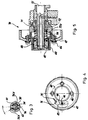
- a single-shaft timing system formed in accordance with the present invention is generally indicated 1.
- This system comprises a camshaft 2 and a phase variator 3.
- the camshaft 2 carries first and second sets of cams constituted by four intake cams, indicated 4a-d and four exhaust cams, indicated 5a-d, respectively.
- the camshaft 2 comprises two tubular half-shafts 6, 7 joined together by a central sleeve 8 and carrying first and second end sleeves 9, 10, respectively, at their axially opposite ends.
- the two half-shafts 6, 7 are fitted with interference in the respective sleeves 8, 9 and 10 so that, once assembled, the camshaft 2 has a unitary character.
- the central sleeve 8 carries the two exhaust cams 5b and 5c as well as a cylindrical surface 11 disposed between them and having a central groove 12 and one or more radial holes 13.
- the surface 11 is held in a bearing 14 of the engine head on which the timing system 1 is mounted.
- the groove 12 and the holes 13 serve for the passage of lubricating oil from a duct in the bearing 14 towards the interior of the camshaft 2 through respective recesses 15 formed in one and/or the other of the abutting surfaces of the two half-shafts 6, 7.
- the first end sleeve 9 carries the exhaust cam 5d and is fitted with interference (force-fitted) on the free end of the half-shaft 7.
- interference force-fitted
- the surface 16 is held in a bearing 19 of the head and the surface 17 faces an oil seal 20 concealed in the bearing 19.
- the groove 18 is engaged by a plate 21 which restrains the shaft 2 axially in the respective bearings whilst allowing it to rotate.
- the second end sleeve 10 is an integral part of the phase variator 3. It is fitted with interference on the free end of the half-shaft 6 and carries the exhaust cam 5a, a flange 22 and an intermediate surface 23 between the cam and the flange.
- the surface 23 is held in a further bearing 24 of the engine head and has a radial hole 25 for the admission of oil under pressure for the active operation of the phase variator 3.
- a further cylindrical surface 26 is formed concentrically with the surface 23 for an oil seal 27 held in a seat 28 in the bearing 24. Behind the surface 26 there is a shoulder 29 for forcing the seal 27 into the seat 28 during the assembly of the shaft 2.
- the camshaft 2 also comprises a pair of rotatable sleeves 30, 31 carrying the intake cams 4a, b and 4c, d, respectively. These sleeves are engaged with radial clearance on the respective free tubular portions of the two half-shafts 6, 7. Between the pairs of cams 4a, 4b and 4c, 4d are respective cylindrical surfaces 32, 33 with radial through-holes 34, 35 in which respective pins 36, 37 are inserted. The cylindrical surfaces 32, 33 are also held in respective bearings 38, 39 of the engine head. For each pin 36, 37 the corresponding half-shaft 6, 7 has a corresponding pair of slot-like holes 36a, 36b for permitting limited relative rotation between the sleeves 30, 31 and the corresponding half-shafts 6, 7. The phase variator 3 controls this rotation in the manner described below.
- the variator 3 comprises a tubular housing 40 which is closed at one end by a cover 41 with a blind hole 42, and which is open at the opposite end where it carries a flange 43 extending radially outwardly.
- the flange 43 has slot-like holes 44 in positions corresponding to those of a similar number of threaded holes 45 in the flange 22. These flanges are clamped together as an assembly by screws 46, by means of which a pulley or similar transmission member 47 is fixed to the variator 3. It will be noted that the slot-like holes 44 permit an adjustment of the relative angular positions of the housing 40 and of the camshaft 2.
- An annular piston 48 slidable in the housing 40, has an internal set of teeth 49 engaged on an external set of teeth 50 of an operating shaft 51 of the variator 3.
- the piston 48 also has an external set of teeth 52 engaged with a corresponding internal set of teeth 53 of the housing 40.
- the shapes of these sets of teeth 49, 50 and 52, 53 are such that sliding of the piston on the shaft 51 corresponds, in known manner, to relative rotation between the housing 40 and the operating shaft 51. For example, one pair of sets of teeth is helical whereas the other pair is straight.
- the piston 48 is urged against the cover 41 by a spring 54.
- a pressurized-oil supply chamber 56 is defined between the facing walls of the piston and of the cover, and a duct 55, arranged as an extension of the hole 25, opens therein.
- the portion of the shaft 51 which is inside the phase variator 3 is supported with its end 60 in the blind hole 42 in the cover 41 but a predominant portion 61 extends out of the variator and is inserted coaxially in the camshaft 2 so as to be rotatable relative thereto.
- Two radial holes 62, 63 are formed in the portion 61 and the pins 36, 37 are driven therein so that, for each rotation of the operating shaft 51 relative to the camshaft 2, there is a corresponding identical rotation of the sleeves 30, 31 and a consequent phase variation of the intake cams 4a-d relative to the exhaust cams 5a-d.
- lubricating oil is supplied to the space between the two through the radial holes 13, 15.
- a variant of the invention is shown in Figure 5 in which details similar to those of the preceding embodiment are indicated by the same reference numerals.
- the variator, generally indicated 70, of this variant can be assembled independently of the camshaft 2 and can be fitted thereon by the force-fitting, on a shank 72 of the camshaft, of a collar 71 which is equivalent, from an operative point of view, to the sleeve portion 10 close to the flange 22 of the previous embodiment.
- the collar 71 has a shoulder 73 for the spring 54 so that the spring keeps the piston 48 in abutment with the cover 41 even when the variator 70 is separated from the camshaft 2.
- the initial phase-setting is adjusted by means of slots, not shown, in the pulley 47 in positions corresponding to those of the screws 46.
- the assembly of the timing system of the invention is particularly simple and effective both with the use of the variator 70, which can be assembled separately, and with the use of the variator 3, and is carried out in the following manner.
- the rotatable sleeves 30, 31 are fitted on the respective half-shafts 6, 7 and the camshaft assembly 2 is locked axially by the forcing of the half-shafts into the respective sleeves 8, 9 and 10.
- the operating shaft 51 is then inserted in the camshaft 2 coaxially.
- the rotatable sleeves 30, 31 are then fixed for rotation with the operating shaft 51 by means of the pins 36, 37.
- the phase variator 3 is then fitted.
- a pin 75 projecting from the flange 22 is intended to engage a corresponding hole (not shown) in a predetermined position in the radial flange 77 of the pulley 47, extending through a slot 76 in the flange 43. This brings about unequivocal relative positioning between the pulley 47 and the camshaft 2 whilst permitting adjustment of the angular position of the housing 40 relative to the shaft 2 by means of the slot 76.
- the timing system thus assembled has a unitary structure, that is, its components are connected to one another and are ready for fitting on the head of an engine.
Landscapes
- Engineering & Computer Science (AREA)
- Mechanical Engineering (AREA)
- General Engineering & Computer Science (AREA)
- Valve-Gear Or Valve Arrangements (AREA)
- Valve Device For Special Equipments (AREA)
Applications Claiming Priority (2)
| Application Number | Priority Date | Filing Date | Title |
|---|---|---|---|
| IT1994PD000087A IT1268966B1 (it) | 1994-05-12 | 1994-05-12 | Sistema di distribuzione monoalbero, in particolare per motori acombustione interna. |
| ITPD940087 | 1994-05-12 |
Publications (3)
| Publication Number | Publication Date |
|---|---|
| EP0686754A2 true EP0686754A2 (de) | 1995-12-13 |
| EP0686754A3 EP0686754A3 (de) | 1996-04-10 |
| EP0686754B1 EP0686754B1 (de) | 1999-10-27 |
Family
ID=11390679
Family Applications (1)
| Application Number | Title | Priority Date | Filing Date |
|---|---|---|---|
| EP95201083A Expired - Lifetime EP0686754B1 (de) | 1994-05-12 | 1995-04-27 | Steuervorrichtung mit einziger Welle, insbesondere für Brennkraftmaschinen |
Country Status (3)
| Country | Link |
|---|---|
| EP (1) | EP0686754B1 (de) |
| DE (1) | DE69512962T2 (de) |
| IT (1) | IT1268966B1 (de) |
Cited By (1)
| Publication number | Priority date | Publication date | Assignee | Title |
|---|---|---|---|---|
| US7513232B2 (en) | 2005-02-03 | 2009-04-07 | Mahle International Gmbh | Adjustable camshaft, in particular for internal combustion engines for motor vehicles having a hydraulic adjusting device |
Families Citing this family (6)
| Publication number | Priority date | Publication date | Assignee | Title |
|---|---|---|---|---|
| DE10346448B4 (de) | 2003-10-07 | 2017-03-30 | Daimler Ag | Nockenwellenversteller für eine Brennkraftmaschine |
| DE202005021715U1 (de) * | 2005-02-03 | 2009-07-02 | Mahle International Gmbh | Nockenwelle mit gegeneinander verdrehbaren Nocken für insbesondere Kraftfahrzeuge |
| DE102005035476B4 (de) | 2005-07-26 | 2022-07-07 | Jörg von Seggern Maschinenbau GmbH | Vorrichtung zum gasdichten Verpacken von Gegenständen |
| DE102005058548B4 (de) * | 2005-12-08 | 2020-11-12 | Audi Ag | Ventiltrieb für eine Verbrennungskraftmaschine |
| DE202006020695U1 (de) * | 2006-05-27 | 2009-06-25 | Mahle International Gmbh | Verstellbare Nockenwelle |
| DE102011076652B4 (de) | 2011-05-27 | 2017-06-01 | Schwäbische Hüttenwerke Automotive GmbH | Vorrichtung zur Verstellung der relativen Drehwinkelposition geschachtelter Nockenwellen |
Family Cites Families (4)
| Publication number | Priority date | Publication date | Assignee | Title |
|---|---|---|---|---|
| GB767645A (en) * | 1954-04-01 | 1957-02-06 | Rene Louis Martin | Improvements in, or relating to valve gear for four stroke internal combustion engines |
| DE3624827A1 (de) * | 1986-07-23 | 1988-02-04 | Sueddeutsche Kolbenbolzenfabri | Verstelleinrichtung fuer eine nockenwelle zum steuern der gasein- und auslassventile von verbrennungsmotoren |
| DE59302331D1 (de) * | 1992-08-13 | 1996-05-30 | Bayerische Motoren Werke Ag | Hubkolben-Brennkraftmaschine mit zwei Gaswechselventilen je Zylinder |
| FR2709786B1 (fr) * | 1993-09-09 | 1995-11-17 | Renault | Arbre à cames pour moteur à combustion interne. |
-
1994
- 1994-05-12 IT IT1994PD000087A patent/IT1268966B1/it active IP Right Grant
-
1995
- 1995-04-27 EP EP95201083A patent/EP0686754B1/de not_active Expired - Lifetime
- 1995-04-27 DE DE69512962T patent/DE69512962T2/de not_active Expired - Fee Related
Cited By (1)
| Publication number | Priority date | Publication date | Assignee | Title |
|---|---|---|---|---|
| US7513232B2 (en) | 2005-02-03 | 2009-04-07 | Mahle International Gmbh | Adjustable camshaft, in particular for internal combustion engines for motor vehicles having a hydraulic adjusting device |
Also Published As
| Publication number | Publication date |
|---|---|
| ITPD940087A0 (it) | 1994-05-12 |
| DE69512962D1 (de) | 1999-12-02 |
| ITPD940087A1 (it) | 1995-11-12 |
| EP0686754B1 (de) | 1999-10-27 |
| DE69512962T2 (de) | 2000-05-04 |
| EP0686754A3 (de) | 1996-04-10 |
| IT1268966B1 (it) | 1997-03-18 |
Similar Documents
| Publication | Publication Date | Title |
|---|---|---|
| DE4029849C2 (de) | Ventilsteuerzeiten-Einstellvorrichtung für Brennkraftmaschinen | |
| US8375906B2 (en) | Camshaft phaser for a concentric camshaft | |
| EP0806550B2 (de) | Ventilzeitsteuerungsvorrichtung | |
| US8757114B2 (en) | Control valve for controlling pressure-medium flows comprising an integrated check valve | |
| US8336512B2 (en) | Camshaft phaser for a concentric camshaft | |
| US11193399B2 (en) | Variable camshaft timing assembly | |
| US8322318B2 (en) | Harmonic drive camshaft phaser with phase authority stops | |
| US5645020A (en) | CAM assembly installation in engine | |
| JPH07507119A (ja) | 駆動結合された2つの軸の間の連続的な角度調節のための装置 | |
| US11125121B2 (en) | Dual actuating variable cam | |
| EP0818610B1 (de) | Ventilzeitsteuervorrichtungen | |
| EP0686754B1 (de) | Steuervorrichtung mit einziger Welle, insbesondere für Brennkraftmaschinen | |
| US20030121485A1 (en) | Hydraulic camshaft adjuster and method for operating the same | |
| US11274577B2 (en) | Variable camshaft timing assembly | |
| US4502427A (en) | Rocker arm for axial engine | |
| US6336433B1 (en) | Apparatus for adjusting the relative angle of a cam shaft | |
| US5150671A (en) | Intake- and/or exhaust-valve timing control system for internal combustion engines | |
| EP0791727B1 (de) | Nockenwelle einer Brennkraftmaschine, die von einer variablen Ventilsteuervorrichtung angetrieben wird | |
| US10626759B2 (en) | Cam phaser between cam bearings | |
| US4694787A (en) | Automatic fluid distributing valve timing device | |
| JPH09317412A (ja) | 内燃機関におけるバルブ開閉特性制御装置 | |
| US11174761B1 (en) | Variable camshaft timing (VCT) phaser assembly and control valve installed remotely | |
| US11852054B2 (en) | Variable camshaft timing system | |
| US20200141285A1 (en) | Cam phaser camshaft coupling | |
| US11280228B2 (en) | Variable camshaft timing assembly |
Legal Events
| Date | Code | Title | Description |
|---|---|---|---|
| PUAI | Public reference made under article 153(3) epc to a published international application that has entered the european phase |
Free format text: ORIGINAL CODE: 0009012 |
|
| AK | Designated contracting states |
Kind code of ref document: A2 Designated state(s): DE FR IT |
|
| PUAL | Search report despatched |
Free format text: ORIGINAL CODE: 0009013 |
|
| AK | Designated contracting states |
Kind code of ref document: A3 Designated state(s): DE FR IT |
|
| 17P | Request for examination filed |
Effective date: 19960911 |
|
| 17Q | First examination report despatched |
Effective date: 19980306 |
|
| GRAG | Despatch of communication of intention to grant |
Free format text: ORIGINAL CODE: EPIDOS AGRA |
|
| GRAG | Despatch of communication of intention to grant |
Free format text: ORIGINAL CODE: EPIDOS AGRA |
|
| GRAH | Despatch of communication of intention to grant a patent |
Free format text: ORIGINAL CODE: EPIDOS IGRA |
|
| GRAH | Despatch of communication of intention to grant a patent |
Free format text: ORIGINAL CODE: EPIDOS IGRA |
|
| GRAA | (expected) grant |
Free format text: ORIGINAL CODE: 0009210 |
|
| AK | Designated contracting states |
Kind code of ref document: B1 Designated state(s): DE FR IT |
|
| ITF | It: translation for a ep patent filed | ||
| REF | Corresponds to: |
Ref document number: 69512962 Country of ref document: DE Date of ref document: 19991202 |
|
| ET | Fr: translation filed | ||
| PLBE | No opposition filed within time limit |
Free format text: ORIGINAL CODE: 0009261 |
|
| STAA | Information on the status of an ep patent application or granted ep patent |
Free format text: STATUS: NO OPPOSITION FILED WITHIN TIME LIMIT |
|
| 26N | No opposition filed | ||
| PGFP | Annual fee paid to national office [announced via postgrant information from national office to epo] |
Ref country code: FR Payment date: 20050412 Year of fee payment: 11 |
|
| PGFP | Annual fee paid to national office [announced via postgrant information from national office to epo] |
Ref country code: DE Payment date: 20050418 Year of fee payment: 11 |
|
| PG25 | Lapsed in a contracting state [announced via postgrant information from national office to epo] |
Ref country code: IT Free format text: LAPSE BECAUSE OF NON-PAYMENT OF DUE FEES;WARNING: LAPSES OF ITALIAN PATENTS WITH EFFECTIVE DATE BEFORE 2007 MAY HAVE OCCURRED AT ANY TIME BEFORE 2007. THE CORRECT EFFECTIVE DATE MAY BE DIFFERENT FROM THE ONE RECORDED. Effective date: 20050427 |
|
| PG25 | Lapsed in a contracting state [announced via postgrant information from national office to epo] |
Ref country code: DE Free format text: LAPSE BECAUSE OF NON-PAYMENT OF DUE FEES Effective date: 20061101 |
|
| REG | Reference to a national code |
Ref country code: FR Ref legal event code: ST Effective date: 20061230 |
|
| PG25 | Lapsed in a contracting state [announced via postgrant information from national office to epo] |
Ref country code: FR Free format text: LAPSE BECAUSE OF NON-PAYMENT OF DUE FEES Effective date: 20060502 |
|
| PGRI | Patent reinstated in contracting state [announced from national office to epo] |
Ref country code: IT Effective date: 20090401 |
|
| PGFP | Annual fee paid to national office [announced via postgrant information from national office to epo] |
Ref country code: IT Payment date: 20060430 Year of fee payment: 12 |
|
| PGRI | Patent reinstated in contracting state [announced from national office to epo] |
Ref country code: IT Effective date: 20090401 |