EP0686776A1 - Soupape à plusieurs functions - Google Patents
Soupape à plusieurs functions Download PDFInfo
- Publication number
- EP0686776A1 EP0686776A1 EP95250090A EP95250090A EP0686776A1 EP 0686776 A1 EP0686776 A1 EP 0686776A1 EP 95250090 A EP95250090 A EP 95250090A EP 95250090 A EP95250090 A EP 95250090A EP 0686776 A1 EP0686776 A1 EP 0686776A1
- Authority
- EP
- European Patent Office
- Prior art keywords
- valve
- piston
- pressure
- differential
- hydraulic system
- Prior art date
- Legal status (The legal status is an assumption and is not a legal conclusion. Google has not performed a legal analysis and makes no representation as to the accuracy of the status listed.)
- Withdrawn
Links
Images


Classifications
-
- F—MECHANICAL ENGINEERING; LIGHTING; HEATING; WEAPONS; BLASTING
- F15—FLUID-PRESSURE ACTUATORS; HYDRAULICS OR PNEUMATICS IN GENERAL
- F15B—SYSTEMS ACTING BY MEANS OF FLUIDS IN GENERAL; FLUID-PRESSURE ACTUATORS, e.g. SERVOMOTORS; DETAILS OF FLUID-PRESSURE SYSTEMS, NOT OTHERWISE PROVIDED FOR
- F15B13/00—Details of servomotor systems ; Valves for servomotor systems
- F15B13/02—Fluid distribution or supply devices characterised by their adaptation to the control of servomotors
Definitions
- the invention relates to a hydraulic system with a high-pressure differential cylinder, which is preferably designed as a servo actuator, and a valve combination, which is hydraulically linked thereto and arranged in a housing, according to the preamble of the main claim.
- a large number of servo actuators are required for actuating wing parts, spoilers, landing gear flaps, etc.
- Each of these drives represents a small hydraulic system with a high-pressure cylinder as the core.
- a valve combination is required, which also includes an electro-hydraulic servo valve (EHSV) as the decisive switching element.
- EHSV electro-hydraulic servo valve
- the object of the invention is to develop a hydraulic system with a high-pressure differential cylinder, preferably designed as a servo actuator, with which different operating states of the servo actuator can be set and which requires a smaller housing with a lower weight for the valve combination.
- the core of the invention is the combination of several individual valves to form a compact multifunction valve which is arranged in an elongated valve housing and in which the adjusting elements lie on a functional axis.
- the advantage of this arrangement can be seen in the fact that, while maintaining all the desired switching functions, the valve housing can be made smaller and thus weight can be saved.
- the essential component of the multifunction valve according to the invention is an axially movable differential piston with two ones different diameter piston areas.
- the resulting pressure-effective surfaces in the piston areas are designed in connection with a spring acting on the differential piston so that when the system is depressurized, the differential piston comes into contact with the mechanical stop and only above a set pressure level that separates the cylinder's entry chamber from the pressure line Holds the poppet valve in the open position.
- the plate seat valve is actuated via a tappet, which is arranged, for example, on the right side of the differential piston.
- a combined damping and switching element is arranged on the other side of the differential piston, with the aid of which the starting process and other operating states can be set.
- a plunger protrudes into the valve housing for the setting of an overpressure protection and the maintenance condition, which cooperates with the end face of the previously mentioned switching element.
- the connections of the tappets are preferably designed as a ball joint in order to prevent the introduction of a transverse force on the differential piston due to the slight inclination of one of the elements.
- a radial indentation in the overflow chamber forms the mechanical stop for both the poppet valve and the differential piston. In the worst case, this can lead to overstressing of the seat valve. This can be avoided, for example, by forming a separate mechanical stop for the differential piston in the pressure chamber, which is designed in such a way that the differential piston comes into contact before the poppet valve is pressed against the aforementioned radial indentation by means of the tappet .
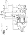
- FIG. 1 shows the multifunction valve 1 according to the invention to fulfill the normal function with, for example, a supply pressure P s > 150 bar.
- a supply pressure P s > 150 bar As soon as the pressure in the supply pressure connection PP exceeds 8 bar, the differential piston B1 moves to the right and closes a bypass edge (not shown here), the bypass connecting the lines P4 to P5.
- the hydraulic fluid flows from the supply connection PP through the axially provided bores 2 into the chamber area 3, which is formed by the bushing 4 and the differential piston B1.
- a connection to the line P1 is established via the bushing 4 and its radial bores 5 and the opposite radial bores 6.
- the pressure acts on the surfaces A2 and A3, which are designed so that the resulting force is greater than the corresponding spring forces F F2 and F F3 .
- the poppet valve E1 is opened against the spring force F F3 by means of the tappet 8 until the valve E1 comes into contact with the radial indentation 9.
- the connection between the right pressure chamber P6 and the overflow chamber P7 is made through the axial bores 10 in the seat valve E1. In this previously explained operating state with P s > 150 bar, this remains Seat valve E1 is always open, regardless of which control is connected to the EHSV.
- the differential cylinder 11 can be extended and retracted by appropriately controlling the EHSV. If the entry command is present (as shown here), the supply pressure line PP is connected via P1 and EHSV and line P4 to the volumes P6 and P7 and thus via line P3 to the entry chamber 12.
- the exit chamber 13 is via P2 and EHSV as well connected to the return PR via P5. However, if there is an exit command, the EHSV switches to the square shown below, so that there is a connection between PP and P2 with the exit chamber 13.
- the entry chamber 12 is then connected to the return PR via P3, P7, P6, P4 and EHSV and P5.
- Figure 2 shows a state with reduced system pressure, for example in the range between 85 and 150 bar. Since the figures are always the same in principle, the same reference numerals have been used for the same parts.
- a reduced pressure is always to be expected if the pump or the pump system does not generate the full prescribed pressure.
- the seat valve E1 should be closed below 150 bar so that the extension of the differential cylinder 11 is prevented by external loads.
- the differential piston B1 still shifts to the right, but the pressure is not sufficient to open the seat valve E1.
- the plunger 8 stops short of the plate of the valve E1.
- the EHSV is switched to the retracted position (as shown here). If the EHSV is brought into the extended position (see FIG. 3), there is an increase in pressure due to the extending differential cylinder 11 in the line P3 and in the overflow chamber P7.
- the increased pressure also acts on the pressure-limiting piston D1, which moves the differential piston B1 to the right via its tappet 14.
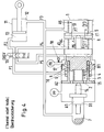
- FIG. 4 shows the state of the overpressure protection. This condition only comes into play when the aircraft is on the ground and the supply pressure PP and the return pressure PR are therefore zero bar. Due to the solar radiation of the wings and the associated heating of the differential cylinder 11, the line P3 and the overflow chamber P7, an increase in pressure occurs in the control lines. At a specified pressure of, for example, 260 bar in P3 / P7, the pressure limiting piston D1 is shifted to the right. The switching element 15 is inserted into the annular gap of the differential piston B1. As soon as this switching element 15 is pushed to the stop, the differential piston B1 is also shifted to the right, so that the poppet valve E1 is opened via the tappet 8.
- the pressure works with the differential area (A1 minus A4, where A1> A4) against the spring force F F2 and F F3 .
- the line P2 is connected to the return PR via the EHSV and P5.
- Line P3 is also connected to P1 via P7, P6, P4, EHSV.
- the connection from P1 to the return PR is established via the holes 6, the overflow channel 16 and the oblique holes 17.
- the maintenance state is shown in FIG.
- the spoiler must free itself with a low force of, for example, 250 N. Let it move up and down.
- the multifunction valve 1 is brought into a specific position by an external lever mechanism.
- the external lever mechanism moves a cam 7, which acts on the differential piston B1 via the switching element 15.
- the differential piston B1 is shifted up to the radial indentation 9 and the seat valve E1 is opened.
- the supply line PP is blocked so that there is no connection to P1 and the spoiler cannot be actuated via a corresponding control of the EHSV. In this way, the risk of injury from unintentional actuation is avoided.
- FIG. 6 shows the position of the multifunction valve 1 after a hydraulic supply error or an electrical control signal error.
- the EHSV switches to the idle state, also called the bias position. This takes place via a reset attached to the EHSV, here in this case by means of a spring 19.
- the seat valve E1 is open and P2 is connected to P5 via the EHSV.
- the connection to the return PR is made via a check valve 18, through which the excess amount can flow off.
- This check valve 18 is preferably biased to 8 bar.
- the closed plate seat valve E1 prevents the differential cylinder 11 from being extended under external loads such as, for example, wind.
- the non-illustrated check valves in the return PR and in the supply line PP prevent air from entering the hydraulic system.
- the EHSV switches to the idle state (bias position). When the electrical signal is restored, the EHSV switches to its original operating state. If an error message occurs, this is registered by the flight control computer, the electricity is taken from the EHSV. When the power is removed, the EHSV resumes its idle state by means of the spring and proceeds as if there was a total loss of hydraulic power, i.e. H. the differential cylinder 11 is retracted and held in the appropriate position.
Landscapes
- Engineering & Computer Science (AREA)
- Physics & Mathematics (AREA)
- Fluid Mechanics (AREA)
- Mechanical Engineering (AREA)
- General Engineering & Computer Science (AREA)
- Fluid-Pressure Circuits (AREA)
- Servomotors (AREA)
- Multiple-Way Valves (AREA)
Applications Claiming Priority (2)
| Application Number | Priority Date | Filing Date | Title |
|---|---|---|---|
| DE4414779 | 1994-04-25 | ||
| DE4414779A DE4414779C1 (de) | 1994-04-25 | 1994-04-25 | Multifunktionsventil |
Publications (1)
| Publication Number | Publication Date |
|---|---|
| EP0686776A1 true EP0686776A1 (fr) | 1995-12-13 |
Family
ID=6516620
Family Applications (1)
| Application Number | Title | Priority Date | Filing Date |
|---|---|---|---|
| EP95250090A Withdrawn EP0686776A1 (fr) | 1994-04-25 | 1995-04-12 | Soupape à plusieurs functions |
Country Status (4)
| Country | Link |
|---|---|
| US (1) | US5572918A (fr) |
| EP (1) | EP0686776A1 (fr) |
| JP (1) | JPH07301207A (fr) |
| DE (1) | DE4414779C1 (fr) |
Cited By (2)
| Publication number | Priority date | Publication date | Assignee | Title |
|---|---|---|---|---|
| DE102012018649A1 (de) * | 2012-09-20 | 2014-03-20 | Liebherr-Aerospace Lindenberg Gmbh | Klappenaktuator |
| CN106553378A (zh) * | 2016-11-22 | 2017-04-05 | 天津舟晗科技有限公司 | 提供稳定压力的电液控制压力机械 |
Families Citing this family (6)
| Publication number | Priority date | Publication date | Assignee | Title |
|---|---|---|---|---|
| DE19637740C2 (de) * | 1996-09-16 | 2001-07-26 | Liebherr Aerospace Gmbh | Hydraulische Anlage |
| USD538889S1 (en) * | 2005-11-23 | 2007-03-20 | Tour & Andersson Ab | Multifunctional valve |
| JP5330193B2 (ja) * | 2009-10-28 | 2013-10-30 | ナブテスコ株式会社 | 背圧加圧弁 |
| USD716912S1 (en) * | 2013-04-23 | 2014-11-04 | Foshan Nanhai Chevan Optical Electronics Co., Ltd. | Three way head |
| EP3693615B1 (fr) | 2019-02-11 | 2025-10-01 | Goodrich Actuation Systems SAS | Agencement de soupape de commande d'actionneur |
| EP3767112B1 (fr) | 2019-07-19 | 2024-09-18 | Goodrich Actuation Systems SAS | Agencement de commande d'actionneur |
Citations (3)
| Publication number | Priority date | Publication date | Assignee | Title |
|---|---|---|---|---|
| US3340895A (en) * | 1965-08-27 | 1967-09-12 | Sanders Associates Inc | Modular pressure regulating and transfer valve |
| US4191094A (en) * | 1978-04-26 | 1980-03-04 | Sundstrand Corporation | Power drive unit |
| US4838308A (en) * | 1987-10-16 | 1989-06-13 | Thomas Charles E | Multipurpose control valve |
Family Cites Families (10)
| Publication number | Priority date | Publication date | Assignee | Title |
|---|---|---|---|---|
| NL103618C (fr) * | 1957-08-26 | |||
| US3053234A (en) * | 1958-03-31 | 1962-09-11 | Bendix Corp | Hydraulic lift systems |
| US2966139A (en) * | 1959-03-09 | 1960-12-27 | Appel Process Ltd | Hydraulic feed means |
| GB1170239A (en) * | 1965-12-22 | 1969-11-12 | Sperry Rand Ltd | Improvements in or relating to Fluid Pressure Operated Reciprocating Motor Systems. |
| SU646102A1 (ru) * | 1977-09-20 | 1979-02-05 | Московский Автомобильно-Дорожный Институт | Шаговый гидропривод |
| JPS5917002A (ja) * | 1982-07-21 | 1984-01-28 | Nippon Steel Corp | 油圧回路 |
| US4700612A (en) * | 1983-05-03 | 1987-10-20 | Swiss Aluminium Ltd. | Electropneumatic drive system for crust breaking devices and process for operating the same |
| DE3611212C1 (de) * | 1986-04-04 | 1987-06-11 | Ernst Dipl-Ing Korthaus | Steuerung fuer Hydraulikzylinder als Antriebe fuer Kolbenpumpen |
| DE3735123A1 (de) * | 1987-10-16 | 1989-06-29 | Hartmann & Laemmle | Hydraulische antriebsvorrichtung |
| DE4244304A1 (de) * | 1992-12-28 | 1994-06-30 | Asea Brown Boveri | Betätigungsvorrichtung für einen hydraulischen Stellantrieb mit druckproportionalem Stellsignal |
-
1994
- 1994-04-25 DE DE4414779A patent/DE4414779C1/de not_active Expired - Fee Related
-
1995
- 1995-04-12 EP EP95250090A patent/EP0686776A1/fr not_active Withdrawn
- 1995-04-25 JP JP7123036A patent/JPH07301207A/ja active Pending
- 1995-04-25 US US08/428,876 patent/US5572918A/en not_active Expired - Fee Related
Patent Citations (3)
| Publication number | Priority date | Publication date | Assignee | Title |
|---|---|---|---|---|
| US3340895A (en) * | 1965-08-27 | 1967-09-12 | Sanders Associates Inc | Modular pressure regulating and transfer valve |
| US4191094A (en) * | 1978-04-26 | 1980-03-04 | Sundstrand Corporation | Power drive unit |
| US4838308A (en) * | 1987-10-16 | 1989-06-13 | Thomas Charles E | Multipurpose control valve |
Cited By (4)
| Publication number | Priority date | Publication date | Assignee | Title |
|---|---|---|---|---|
| DE102012018649A1 (de) * | 2012-09-20 | 2014-03-20 | Liebherr-Aerospace Lindenberg Gmbh | Klappenaktuator |
| US9574578B2 (en) | 2012-09-20 | 2017-02-21 | Liebherr-Aerospace Lindenberg Gmbh | Flap actuator |
| CN106553378A (zh) * | 2016-11-22 | 2017-04-05 | 天津舟晗科技有限公司 | 提供稳定压力的电液控制压力机械 |
| CN106553378B (zh) * | 2016-11-22 | 2018-07-27 | 广东三合液压有限公司 | 提供稳定压力的电液控制压力机械 |
Also Published As
| Publication number | Publication date |
|---|---|
| JPH07301207A (ja) | 1995-11-14 |
| US5572918A (en) | 1996-11-12 |
| DE4414779C1 (de) | 1995-11-02 |
Similar Documents
| Publication | Publication Date | Title |
|---|---|---|
| DE3938417C1 (fr) | ||
| WO2012079908A1 (fr) | Dispositif de soupape d'amortissement réglable | |
| DE2429852A1 (de) | Steuerteil | |
| DE102008059436B3 (de) | Hydraulisches Steuerventil für einen einseitig arbeitenden Differentialzylinder | |
| DE60014685T2 (de) | Hydraulisches system für flugzeugfahrwerk | |
| EP2628959A2 (fr) | Servosoupape | |
| DE3507278A1 (de) | Elektrohydraulische steuereinrichtung | |
| DE4115595A1 (de) | Niveauregeleinrichtung fuer fahrzeuge | |
| DE4414779C1 (de) | Multifunktionsventil | |
| DE2445587A1 (de) | Druckkompensierendes wegeventil | |
| EP0845602B1 (fr) | Dispositif de commande electrohydraulique | |
| DE2926539C2 (de) | Regelventil für Fahrzeugbremsanlagen mit zwei Bremskreisen | |
| EP3303100B1 (fr) | Circuit de positionement hydrostatique et son utilisation | |
| EP0975856A1 (fr) | Dispositif de commande hydraulique pour au moins une soupape de cylindre | |
| EP3446006A1 (fr) | Soupape de fermeture et d'ouverture d'un système de conduites | |
| DE4211551C2 (de) | Verstellpumpe mit einem Druckbegrenzungs- und einem Druckzuschaltventil | |
| DE2052748B2 (de) | Steuerventil fuer einen hydraulischen stellmotor zur betaetigung von steuerflaechen eines luftfahrzeuges | |
| DE3920131C2 (de) | Steuerblock für einen Hydraulikantrieb in einem Flugzeug | |
| EP0935716A1 (fr) | Systeme de valve anti-retour | |
| DE19637740C2 (de) | Hydraulische Anlage | |
| EP4051911B1 (fr) | Système électrohydraulique d'une soupape | |
| DE2519973C3 (de) | Entlastungsventil | |
| DE2837019A1 (de) | Steuerventil fuer eine bremsanlage | |
| EP2740135B1 (fr) | Cylindre différentiel pour un entraînement hydromécanique d'interrupteurs de puissance électriques | |
| DE3022592A1 (de) | Hydraulische steuervorrichtung |
Legal Events
| Date | Code | Title | Description |
|---|---|---|---|
| PUAI | Public reference made under article 153(3) epc to a published international application that has entered the european phase |
Free format text: ORIGINAL CODE: 0009012 |
|
| AK | Designated contracting states |
Kind code of ref document: A1 Designated state(s): DE FR GB IT |
|
| 17P | Request for examination filed |
Effective date: 19951027 |
|
| RAP1 | Party data changed (applicant data changed or rights of an application transferred) |
Owner name: LIEBHERR-AEROSPACE LINDENBERG GMBH |
|
| 17Q | First examination report despatched |
Effective date: 19971216 |
|
| GRAG | Despatch of communication of intention to grant |
Free format text: ORIGINAL CODE: EPIDOS AGRA |
|
| GRAG | Despatch of communication of intention to grant |
Free format text: ORIGINAL CODE: EPIDOS AGRA |
|
| GRAH | Despatch of communication of intention to grant a patent |
Free format text: ORIGINAL CODE: EPIDOS IGRA |
|
| STAA | Information on the status of an ep patent application or granted ep patent |
Free format text: STATUS: THE APPLICATION IS DEEMED TO BE WITHDRAWN |
|
| 18D | Application deemed to be withdrawn |
Effective date: 19990330 |