EP0686816B1 - Vorrichtung für einen Warmwasserbereiter - Google Patents
Vorrichtung für einen Warmwasserbereiter Download PDFInfo
- Publication number
- EP0686816B1 EP0686816B1 EP95850104A EP95850104A EP0686816B1 EP 0686816 B1 EP0686816 B1 EP 0686816B1 EP 95850104 A EP95850104 A EP 95850104A EP 95850104 A EP95850104 A EP 95850104A EP 0686816 B1 EP0686816 B1 EP 0686816B1
- Authority
- EP
- European Patent Office
- Prior art keywords
- water
- flow
- storage tank
- temperature
- valve
- Prior art date
- Legal status (The legal status is an assumption and is not a legal conclusion. Google has not performed a legal analysis and makes no representation as to the accuracy of the status listed.)
- Revoked
Links
Images

Classifications
-
- F—MECHANICAL ENGINEERING; LIGHTING; HEATING; WEAPONS; BLASTING
- F24—HEATING; RANGES; VENTILATING
- F24H—FLUID HEATERS, e.g. WATER OR AIR HEATERS, HAVING HEAT-GENERATING MEANS, e.g. HEAT PUMPS, IN GENERAL
- F24H1/00—Water heaters, e.g. boilers, continuous-flow heaters or water-storage heaters
- F24H1/18—Water-storage heaters
- F24H1/185—Water-storage heaters using electric energy supply
-
- F—MECHANICAL ENGINEERING; LIGHTING; HEATING; WEAPONS; BLASTING
- F24—HEATING; RANGES; VENTILATING
- F24H—FLUID HEATERS, e.g. WATER OR AIR HEATERS, HAVING HEAT-GENERATING MEANS, e.g. HEAT PUMPS, IN GENERAL
- F24H15/00—Control of fluid heaters
- F24H15/10—Control of fluid heaters characterised by the purpose of the control
- F24H15/128—Preventing overheating
-
- F—MECHANICAL ENGINEERING; LIGHTING; HEATING; WEAPONS; BLASTING
- F24—HEATING; RANGES; VENTILATING
- F24H—FLUID HEATERS, e.g. WATER OR AIR HEATERS, HAVING HEAT-GENERATING MEANS, e.g. HEAT PUMPS, IN GENERAL
- F24H15/00—Control of fluid heaters
- F24H15/30—Control of fluid heaters characterised by control outputs; characterised by the components to be controlled
- F24H15/355—Control of heat-generating means in heaters
- F24H15/37—Control of heat-generating means in heaters of electric heaters
-
- F—MECHANICAL ENGINEERING; LIGHTING; HEATING; WEAPONS; BLASTING
- F24—HEATING; RANGES; VENTILATING
- F24H—FLUID HEATERS, e.g. WATER OR AIR HEATERS, HAVING HEAT-GENERATING MEANS, e.g. HEAT PUMPS, IN GENERAL
- F24H9/00—Details
- F24H9/20—Arrangement or mounting of control or safety devices
- F24H9/2007—Arrangement or mounting of control or safety devices for water heaters
- F24H9/2014—Arrangement or mounting of control or safety devices for water heaters using electrical energy supply
- F24H9/2021—Storage heaters
Definitions
- the present invention relates to a device of the type defined in the preamble of claim 1.
- SE laid open patent application 344 631 there is further disclosed a device which controls an electric element's energy output based on the temperature in an external circulation pipe provided between the cold water intake (the bottom area) and the hot water intake (the top area).
- the temperature is controlled by means of a thermostat which governs a control device consisting of one or more thyristors which can connect full or partial power from an electrical energy source.
- EP-A-0309199 discloses a hot water boiling apparatus comprising a hot water tank with a bubble pump unit which sucks cold water from the bottom area of the storage tank, heats it and pumps it as hot water into the top area of the storage tank.
- the bubble pump unit is equipped with non-return valves at the inlet and the outlet, and the pumping effect is obtained by heating the water in the lower part of the bubble pump unit until it boils and forms bubbles, while the sucking effect is obtained by the subsequent condensation of these bubbles when they reaches colder water in the upper part of the bubble pump unit.
- a problem with bubble pumps is that they make noise and have a relatively low energy efficiency since they heat the water up to the boiling point.
- One requirement therefore is to provide a device for water heaters which can accumulate hot water at a constant temperature, e.g. 70°C, independently of the energy supplied as well as to concentrate the energy supplied in order to reduce the accumulation time for consumer hot water.
- a further requirement of the invention is that hot water, which has lower density than cold water and which is added at the top of the water storage tank, should mix to as little an extent as possible with the cold water in the bottom of the storage tank.
- the object of the present invention is to provide a device for water heaters which satisfies these requirements.
- the energy for heating the water can for instance be supplied by a conventional heating element or by a heat exchanger which is connected to hot gas from a heat pump or water-borne energy from one or more energy sources or steam.
- the result of the design according to the present invention is that the hot water which is supplied to the top area of the water storage tank does not mix with the cold water, but remains lying in thin layers with a slowly sinking temperature gradient and without mixing to any noticeable extent with the cold water.
- Figure 1 shows a device which consists of an insulated accumulation storage tank 1, a through-flow device 2 and a temperature-sensitive element 3, which expands under the influence of heat, and where these are connected by pipes 4, 11.
- the storage tank 1 is supplied with cold water through an inlet pipe 5 and supplies hot water through an outlet pipe 6.
- the accumulation of hot water is provided by means of a through-flow device 2, which is provided between the storage tank's 1 bottom area 7 (cold water intake) and the temperature-sensitive element 3, which is connected to the top area 8 (hot water outlet) of the storage tank 1.
- the through-flow device is supplied with a heating element (not shown), e.g. an electric element, which is thermostatically controlled by means of a thermostat 9 and equipped with an overheating control in the form of a further thermostat 10.
- a heating element e.g. an electric element, which is thermostatically controlled by means of a thermostat 9 and equipped with an overheating control in the form of a further thermostat 10.
- the energy which is supplied to the water heater is constant, i.e. the temperature of the water which leaves the through-flow device 2 is not controlled by means of the electric element, but by the actual flow of water through the temperature-sensitive element 3.
- the temperature-sensitive element 3 is opened when the water temperature downstream of the element 3 agrees with the preset temperature and closes when the temperature falls below the preset temperature.
- a piston (not shown) inside the element 3 is fully opened, thus increasing the through-flow of water and thereby mixing it with colder water.
- the device is arranged in such a manner that it never closes completely, but permits a certain amount of water to flow through, in order, amongst other things, to drain off expanded water.
- the temperature-sensitive element 3 which is provided after the through-flow device, viewed in the direction of flow, consequently monitors the accumulation temperature of the water flowing into the upper part of the storage tank.
- the accumulation of hot water continues for as long as the water in the bottom of the storage tank is colder than the preset temperature, the process being stopped thereafter by the element's working thermostat (not shown), which is located in the lower part of the storage tank.
- the water heater according to the invention will have accumulated after approximately 50 minutes 33 litres of 70°C water, which is sufficient hot water for a shower (60 litres at 40°C) as opposed to known water heaters which take up to 7 hours to accumulated hot water at 70°C.
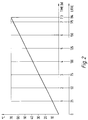
- Figure 2 shows the progress of heating from 5°C to 70°C for a 200 (194) litre water heater, in the form of time consumption and number of litres accumulated of hot water at 70°C.
Landscapes
- Engineering & Computer Science (AREA)
- General Engineering & Computer Science (AREA)
- Chemical & Material Sciences (AREA)
- Thermal Sciences (AREA)
- Combustion & Propulsion (AREA)
- Mechanical Engineering (AREA)
- Physics & Mathematics (AREA)
- Heat-Pump Type And Storage Water Heaters (AREA)
- Yarns And Mechanical Finishing Of Yarns Or Ropes (AREA)
- Electrical Discharge Machining, Electrochemical Machining, And Combined Machining (AREA)
- Water Treatment By Sorption (AREA)
- Cookers (AREA)
- Thermally Insulated Containers For Foods (AREA)
- Details Of Fluid Heaters (AREA)
Claims (3)
- Vorrichtung für einen Warmwasserbereiter bestehend aus einem isolierten Sammelspeichertank (1) gemeinsam mit einer Durchflußeinrichtung (2), worin die Durchflußeinrichtung (2) kaltes Wasser aus dem Bodenbereich (7) des Speichertanks (1) durch eine erste Leitung (11) ansaugt, das Wasser durch ein Heizelement vor einem Zuführen des derart erwärmten Wassers durch eine zweite Leitung (4) zu dem Kopfbereich (8) des Speichertanks (1) aufheizt, dadurch gekennzeichnet, daß die Durchflußeinrichtung (2) mit einem temperaturgesteuerten Durchfluß-Drosselventil (3) ausgestattet ist, welches stromabwärts des Heizelements angeordnet ist und den Wasserdurchfluß in der Einrichtung (2) durch Regulierung der Öffnung des Ventils (3) mit Hilfe eines wärmeempfindlichen Elements reguliert, wobei das Ventil (3) immer ein Durchströmen von wenigstens einer bestimmten, minimalen Menge an Wasser erlaubt und voreinstellbar ist, um eine gewünschte Temperatur des die Einrichtung (2) verlassenden Wassers zur Verfügung zu stellen, wenn eine normale Wassermenge durch die Einrichtung fließt, wobei das Ventil (3) weiter geöffnet wird, um einen vergrößerten Wasserdurchfluß zu erlauben, falls die Temperatur des die Einrichtung (2) verlassenden Wassers einen vorgegebenen Wert überschreitet.
- Warmwasserbereiter nach Anspruch 1, dadurch gekennzeichnet, daß das Heizelement ein elektrisches Element ist, welches durch einen Thermostat (9) Thermostat-gesteuert bzw. -geregelt ist und mit einer Überhitzungssteuerung in Form eines weiteren Thermostats (10) ausgestattet ist.
- Warmwasserbereiter nach Anspruch 1 und 2, dadurch gekennzeichnet, daß die Durchflußeinrichtung (2) mit einem Wärmetauscher ausgestattet ist, welcher mit heißem Gas von einer Wärmepumpe oder mit von Wasser übertragener Energie von einer oder mehreren Energiequellen oder Dampf verbunden ist.
Applications Claiming Priority (4)
| Application Number | Priority Date | Filing Date | Title |
|---|---|---|---|
| NO942156 | 1994-06-09 | ||
| NO942157 | 1994-06-09 | ||
| NO942157A NO942157D0 (no) | 1994-06-09 | 1994-06-09 | Temperaturstyrt mengdestyringsanordning |
| NO942156A NO942156D0 (no) | 1994-06-09 | 1994-06-09 | Vannvarmer optimal |
Publications (2)
| Publication Number | Publication Date |
|---|---|
| EP0686816A1 EP0686816A1 (de) | 1995-12-13 |
| EP0686816B1 true EP0686816B1 (de) | 1999-01-27 |
Family
ID=26648507
Family Applications (1)
| Application Number | Title | Priority Date | Filing Date |
|---|---|---|---|
| EP95850104A Revoked EP0686816B1 (de) | 1994-06-09 | 1995-06-09 | Vorrichtung für einen Warmwasserbereiter |
Country Status (5)
| Country | Link |
|---|---|
| EP (1) | EP0686816B1 (de) |
| AT (1) | ATE176311T1 (de) |
| DE (1) | DE69507540T2 (de) |
| DK (1) | DK0686816T3 (de) |
| ES (1) | ES2130561T3 (de) |
Families Citing this family (4)
| Publication number | Priority date | Publication date | Assignee | Title |
|---|---|---|---|---|
| JP2003106653A (ja) * | 2001-09-28 | 2003-04-09 | Kansai Electric Power Co Inc:The | ヒートポンプ式給湯装置 |
| CN103423860B (zh) * | 2012-05-14 | 2016-05-04 | 厦门奥华斯电器有限公司 | 具有即热与预热双模式的混合式热水器 |
| JP6191014B2 (ja) * | 2014-02-13 | 2017-09-06 | パナソニックIpマネジメント株式会社 | ヒートポンプ給湯装置 |
| DE102023102658A1 (de) * | 2023-02-03 | 2024-08-08 | Citrinsolar Gmbh | Vorrichtung zur steuerung eines durchlauferhitzers für einen schichtladespeicher |
Family Cites Families (3)
| Publication number | Priority date | Publication date | Assignee | Title |
|---|---|---|---|---|
| SE344631B (de) | 1970-08-13 | 1972-04-24 | Thermia Verken Ab | |
| JPS6479542A (en) * | 1987-09-21 | 1989-03-24 | Chubu Electric Power | Hot-water supplier |
| AT397144B (de) * | 1988-03-02 | 1994-02-25 | Heizbetriebe Wien Ges M B H | Steuerung und steuerungsanlage zur erwärmung von brauchwasser |
-
1995
- 1995-06-09 ES ES95850104T patent/ES2130561T3/es not_active Expired - Lifetime
- 1995-06-09 AT AT95850104T patent/ATE176311T1/de not_active IP Right Cessation
- 1995-06-09 EP EP95850104A patent/EP0686816B1/de not_active Revoked
- 1995-06-09 DK DK95850104T patent/DK0686816T3/da active
- 1995-06-09 DE DE69507540T patent/DE69507540T2/de not_active Expired - Fee Related
Also Published As
| Publication number | Publication date |
|---|---|
| DE69507540D1 (de) | 1999-03-11 |
| DE69507540T2 (de) | 1999-09-02 |
| DK0686816T3 (da) | 1999-09-13 |
| ES2130561T3 (es) | 1999-07-01 |
| ATE176311T1 (de) | 1999-02-15 |
| EP0686816A1 (de) | 1995-12-13 |
Similar Documents
| Publication | Publication Date | Title |
|---|---|---|
| SE415796B (sv) | Anordning for varmvattenberedning | |
| CN207922542U (zh) | 具有排废水功能的自动恒温加热装置 | |
| EP0686816A1 (de) | Vorrichtung für einen Warmwasserbereiter | |
| US20040142295A1 (en) | Narrowboat auxiliary heater and method of controlling same | |
| GB2200439A (en) | Instantaneous water heaters for showers | |
| JP3966031B2 (ja) | 多機能給湯装置 | |
| GB2234337A (en) | Domestic water heating assembly | |
| GB2306631A (en) | Domestic water heating apparatus | |
| EP0127344A2 (de) | Verfahren und Vorrichtung zur Flüssigkeitserwärmung | |
| ATE391271T1 (de) | Elektrischer durchlauferhitzer | |
| JP4383238B2 (ja) | 給湯装置 | |
| CN207123072U (zh) | 一种带取暖功能的双用热水器 | |
| GB2200733A (en) | Instantaneous water heaters for showers | |
| GB2181218A (en) | Central heating apparatus | |
| CN222082609U (zh) | 水路结构及净水器 | |
| GB2326703A (en) | Hot Water Supply System | |
| JPH0229944B2 (de) | ||
| WO2002050475A1 (en) | Method and means for pre-heating water | |
| EP1486735B1 (de) | Kombinierte Anlage für Heizung und Brauchwasserbereitung | |
| RU95108439A (ru) | Комбинированный водо- и воздухонагреватель | |
| JPH0599507A (ja) | 蓄熱式給湯器 | |
| CA2415905A1 (en) | Narrowboat auxiliary heater and method of controlling same | |
| JPH08318265A (ja) | 給水装置 | |
| JPS5934818Y2 (ja) | 湯沸器の湯温制御装置 | |
| JPH06300296A (ja) | 給湯装置 |
Legal Events
| Date | Code | Title | Description |
|---|---|---|---|
| PUAI | Public reference made under article 153(3) epc to a published international application that has entered the european phase |
Free format text: ORIGINAL CODE: 0009012 |
|
| AK | Designated contracting states |
Kind code of ref document: A1 Designated state(s): AT BE CH DE DK ES FR GB GR IE IT LI LU MC NL PT SE |
|
| RAX | Requested extension states of the european patent have changed |
Free format text: LT;LV;SI |
|
| 17P | Request for examination filed |
Effective date: 19960605 |
|
| 17Q | First examination report despatched |
Effective date: 19970729 |
|
| GRAG | Despatch of communication of intention to grant |
Free format text: ORIGINAL CODE: EPIDOS AGRA |
|
| GRAG | Despatch of communication of intention to grant |
Free format text: ORIGINAL CODE: EPIDOS AGRA |
|
| GRAH | Despatch of communication of intention to grant a patent |
Free format text: ORIGINAL CODE: EPIDOS IGRA |
|
| GRAH | Despatch of communication of intention to grant a patent |
Free format text: ORIGINAL CODE: EPIDOS IGRA |
|
| GRAA | (expected) grant |
Free format text: ORIGINAL CODE: 0009210 |
|
| AK | Designated contracting states |
Kind code of ref document: B1 Designated state(s): AT BE CH DE DK ES FR GB GR IE IT LI LU MC NL PT SE |
|
| PG25 | Lapsed in a contracting state [announced via postgrant information from national office to epo] |
Ref country code: NL Free format text: LAPSE BECAUSE OF FAILURE TO SUBMIT A TRANSLATION OF THE DESCRIPTION OR TO PAY THE FEE WITHIN THE PRESCRIBED TIME-LIMIT Effective date: 19990127 Ref country code: LI Free format text: LAPSE BECAUSE OF FAILURE TO SUBMIT A TRANSLATION OF THE DESCRIPTION OR TO PAY THE FEE WITHIN THE PRESCRIBED TIME-LIMIT Effective date: 19990127 Ref country code: GR Free format text: LAPSE BECAUSE OF NON-PAYMENT OF DUE FEES Effective date: 19990127 Ref country code: CH Free format text: LAPSE BECAUSE OF FAILURE TO SUBMIT A TRANSLATION OF THE DESCRIPTION OR TO PAY THE FEE WITHIN THE PRESCRIBED TIME-LIMIT Effective date: 19990127 Ref country code: BE Free format text: LAPSE BECAUSE OF FAILURE TO SUBMIT A TRANSLATION OF THE DESCRIPTION OR TO PAY THE FEE WITHIN THE PRESCRIBED TIME-LIMIT Effective date: 19990127 |
|
| REF | Corresponds to: |
Ref document number: 176311 Country of ref document: AT Date of ref document: 19990215 Kind code of ref document: T |
|
| REG | Reference to a national code |
Ref country code: CH Ref legal event code: EP |
|
| REG | Reference to a national code |
Ref country code: IE Ref legal event code: FG4D |
|
| REF | Corresponds to: |
Ref document number: 69507540 Country of ref document: DE Date of ref document: 19990311 |
|
| ITF | It: translation for a ep patent filed | ||
| PG25 | Lapsed in a contracting state [announced via postgrant information from national office to epo] |
Ref country code: PT Free format text: LAPSE BECAUSE OF FAILURE TO SUBMIT A TRANSLATION OF THE DESCRIPTION OR TO PAY THE FEE WITHIN THE PRESCRIBED TIME-LIMIT Effective date: 19990427 |
|
| ET | Fr: translation filed | ||
| PG25 | Lapsed in a contracting state [announced via postgrant information from national office to epo] |
Ref country code: LU Free format text: LAPSE BECAUSE OF NON-PAYMENT OF DUE FEES Effective date: 19990609 Ref country code: IE Free format text: LAPSE BECAUSE OF NON-PAYMENT OF DUE FEES Effective date: 19990609 |
|
| NLV1 | Nl: lapsed or annulled due to failure to fulfill the requirements of art. 29p and 29m of the patents act | ||
| REG | Reference to a national code |
Ref country code: ES Ref legal event code: FG2A Ref document number: 2130561 Country of ref document: ES Kind code of ref document: T3 |
|
| REG | Reference to a national code |
Ref country code: CH Ref legal event code: PL |
|
| REG | Reference to a national code |
Ref country code: DK Ref legal event code: T3 |
|
| PLAV | Examination of admissibility of opposition |
Free format text: ORIGINAL CODE: EPIDOS OPEX |
|
| PLBI | Opposition filed |
Free format text: ORIGINAL CODE: 0009260 |
|
| PLBQ | Unpublished change to opponent data |
Free format text: ORIGINAL CODE: EPIDOS OPPO |
|
| PLBI | Opposition filed |
Free format text: ORIGINAL CODE: 0009260 |
|
| 26 | Opposition filed |
Opponent name: STIEBEL ELTRON GMBH & CO.KG Effective date: 19991020 |
|
| PG25 | Lapsed in a contracting state [announced via postgrant information from national office to epo] |
Ref country code: MC Free format text: LAPSE BECAUSE OF NON-PAYMENT OF DUE FEES Effective date: 19991231 |
|
| 26 | Opposition filed |
Opponent name: JOH. VAILLANT GMBH U. CO. Effective date: 19991027 Opponent name: STIEBEL ELTRON GMBH & CO.KG Effective date: 19991020 |
|
| PLAV | Examination of admissibility of opposition |
Free format text: ORIGINAL CODE: EPIDOS OPEX |
|
| PLBF | Reply of patent proprietor to notice(s) of opposition |
Free format text: ORIGINAL CODE: EPIDOS OBSO |
|
| REG | Reference to a national code |
Ref country code: IE Ref legal event code: MM4A |
|
| PLBF | Reply of patent proprietor to notice(s) of opposition |
Free format text: ORIGINAL CODE: EPIDOS OBSO |
|
| PLBF | Reply of patent proprietor to notice(s) of opposition |
Free format text: ORIGINAL CODE: EPIDOS OBSO |
|
| REG | Reference to a national code |
Ref country code: GB Ref legal event code: IF02 |
|
| RDAH | Patent revoked |
Free format text: ORIGINAL CODE: EPIDOS REVO |
|
| APAC | Appeal dossier modified |
Free format text: ORIGINAL CODE: EPIDOS NOAPO |
|
| APAC | Appeal dossier modified |
Free format text: ORIGINAL CODE: EPIDOS NOAPO |
|
| PLBQ | Unpublished change to opponent data |
Free format text: ORIGINAL CODE: EPIDOS OPPO |
|
| PLAB | Opposition data, opponent's data or that of the opponent's representative modified |
Free format text: ORIGINAL CODE: 0009299OPPO |
|
| R26 | Opposition filed (corrected) |
Opponent name: STIEBEL ELTRON GMBH & CO.KG * 19991027 JOH. VAILLA Effective date: 19991020 |
|
| PLAB | Opposition data, opponent's data or that of the opponent's representative modified |
Free format text: ORIGINAL CODE: 0009299OPPO |
|
| R26 | Opposition filed (corrected) |
Opponent name: VAILLANT GMBH Effective date: 19991027 Opponent name: STIEBEL ELTRON GMBH & CO.KG Effective date: 19991020 |
|
| PGFP | Annual fee paid to national office [announced via postgrant information from national office to epo] |
Ref country code: GB Payment date: 20030509 Year of fee payment: 9 |
|
| PGFP | Annual fee paid to national office [announced via postgrant information from national office to epo] |
Ref country code: SE Payment date: 20030526 Year of fee payment: 9 |
|
| PGFP | Annual fee paid to national office [announced via postgrant information from national office to epo] |
Ref country code: DK Payment date: 20030604 Year of fee payment: 9 |
|
| PGFP | Annual fee paid to national office [announced via postgrant information from national office to epo] |
Ref country code: DE Payment date: 20030617 Year of fee payment: 9 |
|
| PGFP | Annual fee paid to national office [announced via postgrant information from national office to epo] |
Ref country code: AT Payment date: 20030627 Year of fee payment: 9 |
|
| PGFP | Annual fee paid to national office [announced via postgrant information from national office to epo] |
Ref country code: FR Payment date: 20030630 Year of fee payment: 9 |
|
| PGFP | Annual fee paid to national office [announced via postgrant information from national office to epo] |
Ref country code: ES Payment date: 20031016 Year of fee payment: 9 |
|
| APBU | Appeal procedure closed |
Free format text: ORIGINAL CODE: EPIDOSNNOA9O |
|
| RDAG | Patent revoked |
Free format text: ORIGINAL CODE: 0009271 |
|
| STAA | Information on the status of an ep patent application or granted ep patent |
Free format text: STATUS: PATENT REVOKED |
|
| 27W | Patent revoked |
Effective date: 20020304 |
|
| GBPR | Gb: patent revoked under art. 102 of the ep convention designating the uk as contracting state |
Free format text: 20020304 |
|
| REG | Reference to a national code |
Ref country code: SE Ref legal event code: ECNC |
|
| APAA | Appeal reference recorded |
Free format text: ORIGINAL CODE: EPIDOS REFN |
|
| APAH | Appeal reference modified |
Free format text: ORIGINAL CODE: EPIDOSCREFNO |