EP0686827A2 - Dispositif pour la détermination sans contact du profil de la surface d'une pièce - Google Patents
Dispositif pour la détermination sans contact du profil de la surface d'une pièce Download PDFInfo
- Publication number
- EP0686827A2 EP0686827A2 EP95108902A EP95108902A EP0686827A2 EP 0686827 A2 EP0686827 A2 EP 0686827A2 EP 95108902 A EP95108902 A EP 95108902A EP 95108902 A EP95108902 A EP 95108902A EP 0686827 A2 EP0686827 A2 EP 0686827A2
- Authority
- EP
- European Patent Office
- Prior art keywords
- workpiece
- distance
- processing system
- data processing
- determined
- Prior art date
- Legal status (The legal status is an assumption and is not a legal conclusion. Google has not performed a legal analysis and makes no representation as to the accuracy of the status listed.)
- Pending
Links
- 238000005259 measurement Methods 0.000 claims abstract description 14
- 238000000034 method Methods 0.000 claims description 19
- 238000004519 manufacturing process Methods 0.000 claims description 11
- 238000005096 rolling process Methods 0.000 claims description 7
- 230000003746 surface roughness Effects 0.000 claims description 7
- 239000000463 material Substances 0.000 claims description 2
- 230000001105 regulatory effect Effects 0.000 claims 2
- 229910000831 Steel Inorganic materials 0.000 description 4
- 239000010959 steel Substances 0.000 description 4
- 238000010586 diagram Methods 0.000 description 2
- 230000000694 effects Effects 0.000 description 2
- 230000003287 optical effect Effects 0.000 description 2
- 230000002411 adverse Effects 0.000 description 1
- 238000005097 cold rolling Methods 0.000 description 1
- 230000000052 comparative effect Effects 0.000 description 1
- 230000008878 coupling Effects 0.000 description 1
- 238000010168 coupling process Methods 0.000 description 1
- 238000005859 coupling reaction Methods 0.000 description 1
- 238000013016 damping Methods 0.000 description 1
- 230000007547 defect Effects 0.000 description 1
- 230000001419 dependent effect Effects 0.000 description 1
- 238000009826 distribution Methods 0.000 description 1
- 238000012423 maintenance Methods 0.000 description 1
- 230000010355 oscillation Effects 0.000 description 1
- 238000004886 process control Methods 0.000 description 1
- 230000001681 protective effect Effects 0.000 description 1
- 230000005855 radiation Effects 0.000 description 1
- 238000003860 storage Methods 0.000 description 1
- 230000001960 triggered effect Effects 0.000 description 1
Images

Classifications
-
- G—PHYSICS
- G01—MEASURING; TESTING
- G01B—MEASURING LENGTH, THICKNESS OR SIMILAR LINEAR DIMENSIONS; MEASURING ANGLES; MEASURING AREAS; MEASURING IRREGULARITIES OF SURFACES OR CONTOURS
- G01B11/00—Measuring arrangements characterised by the use of optical techniques
- G01B11/30—Measuring arrangements characterised by the use of optical techniques for measuring roughness or irregularity of surfaces
- G01B11/306—Measuring arrangements characterised by the use of optical techniques for measuring roughness or irregularity of surfaces for measuring evenness
Definitions
- the invention relates to a device for the contactless determination of the profile, in particular the roughness of surfaces of a particularly band-shaped workpiece by means of a highly precise distance measuring device, the laser beam of which is directed onto the surface of the workpiece, means being provided which optically split the scattered or reflected laser beam into two Disassemble the light bundle, whereby the photodetectors convert the two light bundles into corresponding electrical signals and the signals can be evaluated by means of a downstream electronics and the distance between the workpiece and the scanning apparatus can be determined, and for a web-shaped determination of the surface profile of the workpiece, the workpiece and the scanning laser beam move during the Move the measuring process relative to each other.
- DE 42 29 313 discloses a method and a device for high-precision distance measurement of surfaces.
- a laser beam is directed onto the surface to be checked, from which the laser beam is scattered or reflected.
- the scattered / reflected light bundle is broken down with optical means into two light bundles with approximately the same surface distribution of the intensities transverse to their direction of radiation. Under these conditions, there is an intensity ratio of the two sub-beams, which is dependent on the main beam direction of the light beam scattered / reflected from the surface.
- the two light bundles are detected photodiodically, the output signals being a measure of the roughness of the surface being tested.
- the object of the invention is therefore to provide a device for the contactless determination of the surface profile of a workpiece, the surface or the surface profile of the workpiece being able to be measured precisely even with workpieces vibrating in the direction of the measuring device. This is to be realized with a few simple and inexpensive parts to be produced, the quality of the workpiece or the workpiece surface not to be reduced by the device or by the measuring process.
- the distance between the surface of the workpiece and the device can be determined by means of a sensor and means are provided which compare the determined distance value with two distance limit values defining a distance interval, the device only then comparing the surface profile of the workpiece determined if the determined distance value is between the distance limit values. If the surface of the workpiece is in the predefined distance range, it is ensured that the surface profile data of the workpiece determined by the device are exact and thus usable.
- the device is advantageously electrically connected to an electronic data processing system by means of a data and control line, the data processing system also being in electrical connection with the transport system transporting the workpiece.
- the device sends a specific signal to the data processing system when the workpiece is in the previously defined distance range from the distance measuring device.
- This signal can be provided by an additional sensor, for example.
- the signal is advantageously a trigger signal which is used for the measurement process Determination of the surface profile of the workpiece starts.
- the device or the additional sensor can also send the trigger signal which triggers the starting process directly to the distance measuring device, which also starts the measurement of the surface profile of the workpiece.
- the device itself or the additional sensor always ensures that the surface profile of the workpiece guided past the distance measuring device is only measured when the workpiece is at a precisely defined distance from the distance measuring device. In this case, the measuring process is triggered immediately. Since the measurement at very high belt speeds only takes a few milliseconds, the change in distance between the distance measuring device and the workpiece within the measuring time is negligible.
- the additional sensor can also advantageously be used for arithmetic matching of the profile data measured by the distance measuring device, so that offset errors caused by the vibrating workpiece can be eliminated.
- Such a device increases the effectiveness of the production process enormously, since stopping the production process or additional damping measures are not required, which significantly reduces the production costs.
- the device determines exact values via the surface profile of the workpiece, as a result of which all surface quality and roughness parameters can advantageously be determined or calculated. It is also possible to determine the peak number P c , which is an important quality criterion for evaluating the surface quality, especially for the processing industry.
- P c is an important quality criterion for evaluating the surface quality, especially for the processing industry.
- Such a device is not only small and compact in its dimensions, but is also insensitive to dirt and impact.
- the electronic data processing system advantageously receives the data relevant to the distance measurement, in particular the speed and / or dimensions and / or the material, from the transport or rolling system and / or the temperature of the workpiece. By coupling these three devices, an optimal utilization of the production plant is achieved.
- the high-precision distance device is controlled by means of the data processing system and the software running on it, the profile data is stored in the memory of the data processing system, processed and then displayed optically on a display medium.
- the measurement result can also be stored on external storage media or output on a printer.
- the data processing system determines all parameters of the surface profile that are necessary for determining the surface roughness of the workpiece. If the data processing system determines roughness or surface profile parameters that do not correspond to the specified values, an error analysis can be carried out by the data processing system. If the data processing system determines that the rollers responsible for the surface quality of the workpiece no longer meet the required requirements, the data processing system triggers an alarm or stops the production process and issues instructions that the corresponding roller must be replaced. The exact time for changing the corresponding rollers can also be determined from the quality of the surface roughness which deteriorates over time, as a result of which the maintenance and repair work necessary for the production process can be initiated early, so that the production downtime is minimized.
- the data processing system advantageously controls the high-precision distance measuring device, the control or Control parameters for the entire measurement process on the data processing system of a suitable input medium can be set.
- the data processing system can additionally independently determine the control parameters for the measuring process on the basis of the data transmitted by the transport or rolling system. This largely eliminates errors that are made due to incorrect inputs by the operating personnel.
- a plurality of devices for determining the surface profile of the workpiece are arranged next to one another at intervals, so that a plurality of surface profile paths can be determined. It is also advantageous if a plurality of devices can be arranged one behind the other at intervals, so that the same surface section of the workpiece can be checked several times during the entire production process. The simultaneous control of the surface profile of the workpiece at several points allows a representative statement about the entire surface condition or the profile of the workpiece.
- the high-precision distance measuring device and the additional sensor are arranged directly behind a roller above or below the workpiece, depending on which side of the workpiece surface is to be checked, since the workpiece passes directly behind the rollers this is firmly clamped and no large vibration amplitudes are to be expected.
- the high-precision distance measuring device and the additional sensor can be moved over the workpiece by means of a device, in particular transversely to the transport movement of the workpiece. This makes it possible to successively determine the surface profile of the workpiece over the entire roller width during the rolling process or to check the surface profile of the workpiece only where the rollers are subject to increased wear due to the process.
- the high-precision distance measuring device and the additional sensor have calibration devices which set the required distance from the workpiece by means of electric motors, in particular stepping or servo motors, the data processing system controlling the calibration process.
- the automation of the calibration process shortens the process downtime, which means that the otherwise expensive and highly qualified personnel can be assigned to other activities.
- the device according to the invention can be used for determining the surface profile of workpieces wherever the workpiece to be tested reflects the laser beam sufficiently.
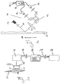
- the 1 shows a highly accurate distance measuring device A, which uses a laser 1 to generate a laser beam 3 which is directed onto and from the one surface of the workpiece 2 is reflected.
- the reflected light or laser beam 4 is split up into two light beams by means of an optical system 5, each of which is converted into electrical signals by a photodetector 6 and fed to a downstream electronics 7.
- the downstream electronics 7 compares the electrical signals of the photodetectors 6 and transmits the measured distance or profile data via the data lines 8 to the data processing system 9, not shown.
- the workpiece 2 moves in the direction R.
- the high-precision distance measuring device A being connected to the data processing system 9 via data and control lines 8, and the data processing system 9 being additionally connected to the process control station 11 by means of electrical data or control lines 10.
- the data processing system 9 or the high-precision distance measuring device A can additionally be connected to an additional sensor, also not shown, by means of electrical lines (not shown), the additional sensor sending a specific signal to the
- Data processing system 9 or the distance measuring device A sends out when the workpiece 2 is in a certain distance range to the distance measuring device A.
- the specific signal is a trigger signal that starts the measurement process.
- the specific signal can also be sent by the distance measuring device A itself.
- FIG. 3 shows the distance measuring device A, which is in a protective box, the distance measuring device A having a calibration device 15, by means of which the distance D between the workpiece 2 and the distance measuring device A can be set.
- the calibration device 15 has an electric motor 14 by means of which the distance D can be set automatically.
- the workpiece 2 is pressurized by the rollers 12 and 13 and additionally moved in the R direction.
- the roller 13 has a certain surface profile which is pressed into the lower side of the workpiece 2.
- FIG. 4 shows the high-precision distance measuring device A, which is attached to a rail 16 and can be moved in the direction Q transversely to the transport direction R of the workpiece 2 by means of a drive, not shown. The measurement of the surface profile is thus possible over the entire width of the workpiece 2.
Landscapes
- Physics & Mathematics (AREA)
- General Physics & Mathematics (AREA)
- Length Measuring Devices By Optical Means (AREA)
- Length Measuring Devices With Unspecified Measuring Means (AREA)
Applications Claiming Priority (2)
| Application Number | Priority Date | Filing Date | Title |
|---|---|---|---|
| DE4420293 | 1994-06-10 | ||
| DE19944420293 DE4420293A1 (de) | 1994-06-10 | 1994-06-10 | Vorrichtung zur berührungslosen Bestimmung des Oberflächenprofils eines Werkstücks |
Publications (2)
| Publication Number | Publication Date |
|---|---|
| EP0686827A2 true EP0686827A2 (fr) | 1995-12-13 |
| EP0686827A3 EP0686827A3 (fr) | 1996-10-23 |
Family
ID=6520261
Family Applications (1)
| Application Number | Title | Priority Date | Filing Date |
|---|---|---|---|
| EP95108902A Pending EP0686827A3 (fr) | 1994-06-10 | 1995-06-09 | Dispositif pour la détermination sans contact du profil de la surface d'une pièce |
Country Status (2)
| Country | Link |
|---|---|
| EP (1) | EP0686827A3 (fr) |
| DE (1) | DE4420293A1 (fr) |
Cited By (6)
| Publication number | Priority date | Publication date | Assignee | Title |
|---|---|---|---|---|
| EP0992763A3 (fr) * | 1998-10-06 | 2001-02-07 | Techint Compagnia Tecnica Internazionale S.P.A. | Procédé et appareil pour la mesure des déviations de forme de surfaces usinées |
| RU2285234C2 (ru) * | 2004-10-28 | 2006-10-10 | Войсковая часть 75360 | Лазерный профилометр |
| RU2361175C2 (ru) * | 2006-10-20 | 2009-07-10 | Войсковая часть 75360 | Лазерный профилометр |
| RU2362118C2 (ru) * | 2006-11-24 | 2009-07-20 | Войсковая часть 75360 | Лазерный профилометр |
| EP3171125A1 (fr) * | 2015-11-19 | 2017-05-24 | Sick Ag | Procede de reconnaissance d'un profil d'un systeme passant dans une zone de detection d'un capteur de distance |
| CN117463545A (zh) * | 2023-11-02 | 2024-01-30 | 阳江大金风电海洋工程科技有限公司 | 一种塔筒涂装机构 |
Families Citing this family (1)
| Publication number | Priority date | Publication date | Assignee | Title |
|---|---|---|---|---|
| DE19717593A1 (de) * | 1997-04-25 | 1998-10-29 | Duerr Systems Gmbh | Meßsystem zur Beurteilung der Oberflächenqualität |
Citations (1)
| Publication number | Priority date | Publication date | Assignee | Title |
|---|---|---|---|---|
| DE4229313A1 (de) | 1992-09-02 | 1994-03-03 | Betr Forsch Inst Angew Forsch | Verfahren und Vorrichtung zur hochgenauen Abstandsmessung von Oberflächen |
Family Cites Families (11)
| Publication number | Priority date | Publication date | Assignee | Title |
|---|---|---|---|---|
| US3671726A (en) * | 1969-05-23 | 1972-06-20 | Morvue Inc | Electro-optical apparatus for precise on-line measurement of the thickness of moving strip material |
| US4017188A (en) * | 1975-02-26 | 1977-04-12 | The Bendix Corporation | Surface profile measuring device and method |
| US3994586A (en) * | 1975-10-30 | 1976-11-30 | Aluminum Company Of America | Simultaneous determination of film uniformity and thickness |
| US4298286A (en) * | 1980-06-02 | 1981-11-03 | The Carl Maxey Company | Measuring apparatus |
| DE3322710C2 (de) * | 1983-06-24 | 1986-05-28 | Daimler-Benz Ag, 7000 Stuttgart | Optische Abstandsmeßvorrichtung |
| US4908508A (en) * | 1987-02-12 | 1990-03-13 | Akzo N.V. | Process and apparatus for determining thicknesses of layers |
| DE3840820A1 (de) * | 1988-12-03 | 1990-06-07 | Breitmeier Ulrich | Messkopf |
| DE3913159A1 (de) * | 1989-04-21 | 1990-10-25 | Linsinger Maschinenbau Gmbh | Verfahren und vorrichtung zur messung von wellenfoermigen deformationen an wenigstens einer schienenoberseite (schienenlaufflaeche) eines schienenweges |
| DE3924290A1 (de) * | 1989-07-22 | 1991-01-31 | Fraunhofer Ges Forschung | Vorrichtung zur optischen abstandsmessung |
| US5017012A (en) * | 1989-08-04 | 1991-05-21 | Chapman Instruments, Inc. | Viewing system for surface profiler |
| EP0486713B1 (fr) * | 1990-11-19 | 1994-07-13 | FAG Kugelfischer Georg Schäfer Aktiengesellschaft | Dispositif de mesure de l'épaisseur |
-
1994
- 1994-06-10 DE DE19944420293 patent/DE4420293A1/de not_active Withdrawn
-
1995
- 1995-06-09 EP EP95108902A patent/EP0686827A3/fr active Pending
Patent Citations (1)
| Publication number | Priority date | Publication date | Assignee | Title |
|---|---|---|---|---|
| DE4229313A1 (de) | 1992-09-02 | 1994-03-03 | Betr Forsch Inst Angew Forsch | Verfahren und Vorrichtung zur hochgenauen Abstandsmessung von Oberflächen |
Cited By (7)
| Publication number | Priority date | Publication date | Assignee | Title |
|---|---|---|---|---|
| EP0992763A3 (fr) * | 1998-10-06 | 2001-02-07 | Techint Compagnia Tecnica Internazionale S.P.A. | Procédé et appareil pour la mesure des déviations de forme de surfaces usinées |
| RU2285234C2 (ru) * | 2004-10-28 | 2006-10-10 | Войсковая часть 75360 | Лазерный профилометр |
| RU2361175C2 (ru) * | 2006-10-20 | 2009-07-10 | Войсковая часть 75360 | Лазерный профилометр |
| RU2362118C2 (ru) * | 2006-11-24 | 2009-07-20 | Войсковая часть 75360 | Лазерный профилометр |
| EP3171125A1 (fr) * | 2015-11-19 | 2017-05-24 | Sick Ag | Procede de reconnaissance d'un profil d'un systeme passant dans une zone de detection d'un capteur de distance |
| CN117463545A (zh) * | 2023-11-02 | 2024-01-30 | 阳江大金风电海洋工程科技有限公司 | 一种塔筒涂装机构 |
| CN117463545B (zh) * | 2023-11-02 | 2024-05-03 | 阳江大金风电海洋工程科技有限公司 | 一种塔筒涂装机构 |
Also Published As
| Publication number | Publication date |
|---|---|
| DE4420293A1 (de) | 1995-12-14 |
| EP0686827A3 (fr) | 1996-10-23 |
Similar Documents
| Publication | Publication Date | Title |
|---|---|---|
| EP0208060B1 (fr) | Méthode et dispositif pour la détermination de diamètres des roues de paires de roues | |
| EP0212052A2 (fr) | Dispositif pour la mesure des roues d'ensembles de roues intégrées dans le véhicule | |
| EP1241462B1 (fr) | Mesure en continu pour la détection du positionnement correct ou pour le test de qualité de paires d'engrenages | |
| WO2010049209A1 (fr) | Procédé et dispositif de détermination d'une planéité d'un ruban métallique | |
| DE4411263C2 (de) | Verfahren zur Überprüfung der Führungsgenauigkeit einer Brennschneidmaschine und Anordnung zur Durchführung des Verfahrens | |
| WO2020239755A1 (fr) | Dispositif et procédé de mesure d'épaisseur d'objets à mesurer mobiles en forme de ruban ou de plaque | |
| WO1993004338A1 (fr) | Procede et dispositif d'evaluation quantifiable de l'impression physiologique produite par des surfaces reflechissantes | |
| EP0686827A2 (fr) | Dispositif pour la détermination sans contact du profil de la surface d'une pièce | |
| DE3913159A1 (de) | Verfahren und vorrichtung zur messung von wellenfoermigen deformationen an wenigstens einer schienenoberseite (schienenlaufflaeche) eines schienenweges | |
| DE10256123B4 (de) | Verfahren und Vorrichtung zur Ermittlung einer Zustandsgröße, insbesondere des Laufflächenprofils, einer Schiene | |
| DE10010019C1 (de) | Verfahren zur optoelektronischen Zustandsüberwachung rotierender Laufräder von Schienenfahrzeugen | |
| EP3253507B1 (fr) | Dispositif de pliage avec instrument de mesure | |
| EP2143525A2 (fr) | Procédé et dispositif de positionnement d'une pièce à usiner par rapport à un outil | |
| EP2583764A2 (fr) | Method for controlling a production assembly by means of high resolution tracking of the produced workpieces | |
| DE10256122B4 (de) | Verfahren und Vorrichtung zur Ermittlung wenigstens einer Zustandsgröße einer Rad-Schiene-Paarung | |
| DE102010047137A1 (de) | Verfahren und Vorrichtung zur Überwachung der Herstellung von Verlege- und Verriegelungsprofilen von Laminatpaneelen | |
| EP4326999B1 (fr) | Procédé et machine d'usinage pour déterminer l'état d'une propulsion pignon et crémaillère pour un axe de parcours | |
| DE2852157A1 (de) | Verfahren und vorrichtung zum ausrichten der achse eines zylindrischen werkstuecks | |
| DE4317410C2 (de) | Verfahren und Vorrichtung zur berührungslosen Messung von Werkstücken mit großen Durchmesserdifferenzen an Werkzeugmaschinen | |
| DE3703429C2 (fr) | ||
| DE4103166A1 (de) | Qualitaetskontroll-vorrichtung | |
| EP0918978A1 (fr) | Procede et dispositif pour mesurer la largeur de recouvrement d'une jonction a recouvrement de deux pieces superposees a plat | |
| DE2850576A1 (de) | Verfahren zur fluchtenden ausrichtung von maschinenelementen | |
| EP2523776A1 (fr) | Dispositif et procédé de détermination de la position d'une surface de travail d'un disque de travail | |
| DE202019102968U1 (de) | Vorrichtung zur Dickenmessung an bewegten bahn- oder plattenförmigen Messobjekten |
Legal Events
| Date | Code | Title | Description |
|---|---|---|---|
| PUAI | Public reference made under article 153(3) epc to a published international application that has entered the european phase |
Free format text: ORIGINAL CODE: 0009012 |
|
| AK | Designated contracting states |
Kind code of ref document: A2 Designated state(s): AT BE CH DE DK ES FR GB GR IE IT LI LU NL PT SE |
|
| PUAL | Search report despatched |
Free format text: ORIGINAL CODE: 0009013 |
|
| RHK1 | Main classification (correction) |
Ipc: G01B 11/30 |
|
| AK | Designated contracting states |
Kind code of ref document: A3 Designated state(s): AT BE CH DE DK ES FR GB GR IE IT LI LU NL PT SE |
|
| 17P | Request for examination filed |
Effective date: 19970418 |
|
| RAP1 | Party data changed (applicant data changed or rights of an application transferred) |
Owner name: MESSELEKTRONIK DRESDEN GMBH |
|
| PUAJ | Public notification under rule 129 epc |
Free format text: ORIGINAL CODE: 0009425 |
|
| 18D | Application deemed to be withdrawn |
Effective date: 19990104 |
|
| D18D | Application deemed to be withdrawn (deleted) | ||
| STAA | Information on the status of an ep patent application or granted ep patent |
Free format text: STATUS: THE APPLICATION IS DEEMED TO BE WITHDRAWN |
|
| R18D | Application deemed to be withdrawn (corrected) |
Effective date: 19981231 |