EP0686831A2 - Appareil de mesure du débit - Google Patents
Appareil de mesure du débit Download PDFInfo
- Publication number
- EP0686831A2 EP0686831A2 EP95108199A EP95108199A EP0686831A2 EP 0686831 A2 EP0686831 A2 EP 0686831A2 EP 95108199 A EP95108199 A EP 95108199A EP 95108199 A EP95108199 A EP 95108199A EP 0686831 A2 EP0686831 A2 EP 0686831A2
- Authority
- EP
- European Patent Office
- Prior art keywords
- differential pressure
- pressure lines
- line
- throttle
- flow meter
- Prior art date
- Legal status (The legal status is an assumption and is not a legal conclusion. Google has not performed a legal analysis and makes no representation as to the accuracy of the status listed.)
- Granted
Links
- 238000011156 evaluation Methods 0.000 claims abstract description 5
- 239000007788 liquid Substances 0.000 claims description 3
- 238000005259 measurement Methods 0.000 abstract description 7
- 238000004519 manufacturing process Methods 0.000 description 3
- 238000007789 sealing Methods 0.000 description 3
- 238000010276 construction Methods 0.000 description 1
- 230000003247 decreasing effect Effects 0.000 description 1
- 238000001514 detection method Methods 0.000 description 1
- 238000010586 diagram Methods 0.000 description 1
- 238000000605 extraction Methods 0.000 description 1
- 238000010438 heat treatment Methods 0.000 description 1
- 238000009434 installation Methods 0.000 description 1
- 238000000691 measurement method Methods 0.000 description 1
- 238000000034 method Methods 0.000 description 1
- 238000010079 rubber tapping Methods 0.000 description 1
- 210000002023 somite Anatomy 0.000 description 1
Images

Classifications
-
- G—PHYSICS
- G01—MEASURING; TESTING
- G01F—MEASURING VOLUME, VOLUME FLOW, MASS FLOW OR LIQUID LEVEL; METERING BY VOLUME
- G01F1/00—Measuring the volume flow or mass flow of fluid or fluent solid material wherein the fluid passes through a meter in a continuous flow
- G01F1/05—Measuring the volume flow or mass flow of fluid or fluent solid material wherein the fluid passes through a meter in a continuous flow by using mechanical effects
- G01F1/34—Measuring the volume flow or mass flow of fluid or fluent solid material wherein the fluid passes through a meter in a continuous flow by using mechanical effects by measuring pressure or differential pressure
- G01F1/36—Measuring the volume flow or mass flow of fluid or fluent solid material wherein the fluid passes through a meter in a continuous flow by using mechanical effects by measuring pressure or differential pressure the pressure or differential pressure being created by the use of flow constriction
- G01F1/363—Measuring the volume flow or mass flow of fluid or fluent solid material wherein the fluid passes through a meter in a continuous flow by using mechanical effects by measuring pressure or differential pressure the pressure or differential pressure being created by the use of flow constriction with electrical or electro-mechanical indication
-
- G—PHYSICS
- G01—MEASURING; TESTING
- G01F—MEASURING VOLUME, VOLUME FLOW, MASS FLOW OR LIQUID LEVEL; METERING BY VOLUME
- G01F1/00—Measuring the volume flow or mass flow of fluid or fluent solid material wherein the fluid passes through a meter in a continuous flow
- G01F1/05—Measuring the volume flow or mass flow of fluid or fluent solid material wherein the fluid passes through a meter in a continuous flow by using mechanical effects
- G01F1/34—Measuring the volume flow or mass flow of fluid or fluent solid material wherein the fluid passes through a meter in a continuous flow by using mechanical effects by measuring pressure or differential pressure
- G01F1/36—Measuring the volume flow or mass flow of fluid or fluent solid material wherein the fluid passes through a meter in a continuous flow by using mechanical effects by measuring pressure or differential pressure the pressure or differential pressure being created by the use of flow constriction
- G01F1/40—Details of construction of the flow constriction devices
-
- G—PHYSICS
- G01—MEASURING; TESTING
- G01F—MEASURING VOLUME, VOLUME FLOW, MASS FLOW OR LIQUID LEVEL; METERING BY VOLUME
- G01F1/00—Measuring the volume flow or mass flow of fluid or fluent solid material wherein the fluid passes through a meter in a continuous flow
- G01F1/05—Measuring the volume flow or mass flow of fluid or fluent solid material wherein the fluid passes through a meter in a continuous flow by using mechanical effects
- G01F1/34—Measuring the volume flow or mass flow of fluid or fluent solid material wherein the fluid passes through a meter in a continuous flow by using mechanical effects by measuring pressure or differential pressure
- G01F1/36—Measuring the volume flow or mass flow of fluid or fluent solid material wherein the fluid passes through a meter in a continuous flow by using mechanical effects by measuring pressure or differential pressure the pressure or differential pressure being created by the use of flow constriction
- G01F1/40—Details of construction of the flow constriction devices
- G01F1/42—Orifices or nozzles
Definitions
- the invention relates to a flow measuring device for liquid or gaseous products, consisting of an arrangement of the measured value of a throttle inserted into a line leading the product to be measured and the pressure lines connected to the line on both sides of the throttle and of a transducer connected to the latter, the output of which is connected to an evaluation and display unit.
- Throttles 1 for example orifices, nozzles are installed in the flowing medium. This creates a pressure difference between both sides of the throttle.
- the differential pressure is recorded at bores 2 in the tube wall and is forwarded to differential pressure transducer 3 by means of differential pressure lines 4 of any length, which contain various shut-off elements 5.
- the present invention is accordingly based on the object of developing a flow meter which is less expensive than in construction and in assembly the usual devices and safe and simple operation guaranteed.
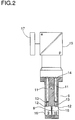
- the part of the flow meter which records the measured values can be seen as a one-piece functional block 6 in longitudinal section.
- the throttle 8 including line sections 9 and 10 and differential pressure lines 11 are incorporated with the pressure tapping channels 13 opening into bores 12 in the line sections.
- the throttle for example an orifice or nozzle, is part of the line sections and e.g. already connected to them through the manufacturing process.
- the bores are dimensioned so that there is always turbulent flow in the narrowest cross section and the measured values are therefore independent of the Reynolds number.
- the differential pressure lines 11 open in the upper part of the workpiece 7 into a connecting flange 14, the standard sealing surface of which enables the connection of a transmitter 15 regardless of the origin.
- the output of the transmitter is connected to an evaluation and display unit 17, by means of which the flow measurement value can be read and, if necessary, is available for further processing. Both the transmitter and the evaluation and display unit are devices that are available in specialist shops and therefore do not need to be described further.
- the workpiece is also provided with standard-compliant sealing surfaces 16 at the openings of the line sections 9 and 10, so that the sensor 6 can be clamped between the standard flanges of a product line.
Landscapes
- Physics & Mathematics (AREA)
- Fluid Mechanics (AREA)
- General Physics & Mathematics (AREA)
- Measuring Volume Flow (AREA)
Applications Claiming Priority (2)
| Application Number | Priority Date | Filing Date | Title |
|---|---|---|---|
| DE4419846A DE4419846A1 (de) | 1994-06-07 | 1994-06-07 | Durchflußmeßgerät |
| DE4419846 | 1994-06-07 |
Publications (3)
| Publication Number | Publication Date |
|---|---|
| EP0686831A2 true EP0686831A2 (fr) | 1995-12-13 |
| EP0686831A3 EP0686831A3 (fr) | 1996-07-17 |
| EP0686831B1 EP0686831B1 (fr) | 2002-05-02 |
Family
ID=6519977
Family Applications (1)
| Application Number | Title | Priority Date | Filing Date |
|---|---|---|---|
| EP95108199A Expired - Lifetime EP0686831B1 (fr) | 1994-06-07 | 1995-05-30 | Appareil de mesure du débit |
Country Status (2)
| Country | Link |
|---|---|
| EP (1) | EP0686831B1 (fr) |
| DE (2) | DE4419846A1 (fr) |
Cited By (2)
| Publication number | Priority date | Publication date | Assignee | Title |
|---|---|---|---|---|
| GB2301676B (en) * | 1995-05-31 | 1999-04-28 | Hattersley Newman Hender | A Fluid metering station |
| WO2001020267A1 (fr) * | 1999-09-13 | 2001-03-22 | Rosemount Inc. | Debitmetre a pression differentielle dote de prises de pression integrees |
Family Cites Families (2)
| Publication number | Priority date | Publication date | Assignee | Title |
|---|---|---|---|---|
| US3822592A (en) * | 1973-03-29 | 1974-07-09 | Fischer & Porter Co | Integral orifice assembly for head meters |
| DE4025323C2 (de) * | 1990-08-10 | 1993-12-02 | Oventrop Sohn Kg F W | Vorrichtung zur Durchflußmessung an Heizkörpern |
-
1994
- 1994-06-07 DE DE4419846A patent/DE4419846A1/de not_active Withdrawn
-
1995
- 1995-05-30 EP EP95108199A patent/EP0686831B1/fr not_active Expired - Lifetime
- 1995-05-30 DE DE59510187T patent/DE59510187D1/de not_active Expired - Lifetime
Non-Patent Citations (1)
| Title |
|---|
| None |
Cited By (2)
| Publication number | Priority date | Publication date | Assignee | Title |
|---|---|---|---|---|
| GB2301676B (en) * | 1995-05-31 | 1999-04-28 | Hattersley Newman Hender | A Fluid metering station |
| WO2001020267A1 (fr) * | 1999-09-13 | 2001-03-22 | Rosemount Inc. | Debitmetre a pression differentielle dote de prises de pression integrees |
Also Published As
| Publication number | Publication date |
|---|---|
| EP0686831B1 (fr) | 2002-05-02 |
| DE4419846A1 (de) | 1995-12-14 |
| EP0686831A3 (fr) | 1996-07-17 |
| DE59510187D1 (de) | 2002-06-06 |
Similar Documents
| Publication | Publication Date | Title |
|---|---|---|
| DE19982582B3 (de) | Reibungsdurchflußmesser | |
| DE60029196T2 (de) | Strömungsmessung mit diagnostischen mitteln | |
| DE60024283T2 (de) | Durchflussplatte mit temperaturmessmerkmal | |
| EP3296704A1 (fr) | Debimetre | |
| EP0254160A1 (fr) | Dispositif pour mesurer le débit massique dans un tube | |
| DE1195103B (de) | Leckanzeigeeinrichtung fuer Wellrohrkompensatoren | |
| DE102016108761A1 (de) | Strömungskonditionierer mit einem integrierten Druckmessstutzen | |
| DE102015111642A1 (de) | Durchflussmessgerät nach dem Wirbelzählerprinzip | |
| EP1821009B1 (fr) | Dispositif de vérification destiné à l'enregistrement de l'émission de vapeur au niveau d'au moins un endroit de fuite, de préférence dans les joints glissants, en particulier dans le domaine automobile | |
| DE3900836A1 (de) | Verfahren zur messung der steuerquerschnittsflaeche einer duese | |
| DE3855311T2 (de) | Anordnung zur messung des volumenflusses eines ventilators | |
| EP0686831B1 (fr) | Appareil de mesure du débit | |
| DE4205453C2 (de) | Einrichtung zum Messen von hydraulischen Durchflußmengen und Leckagen an einem Prüfling | |
| EP0344618B1 (fr) | Dispositif de prélèvement d'échantillon de gaz | |
| EP2241864B1 (fr) | Dispositif de mesure du débit d'un fluid avec un dispositif de liaison pour le capteur | |
| DE2405786B2 (de) | Meßeinrichtung zur Gasstrommessung, insbesondere in Gasabsaugeleitungen | |
| EP0887626A1 (fr) | Ensembles de substitution pour débitmètres de volume et débitmètres à tourbillon correspondants | |
| EP0183987B1 (fr) | Dispositif pour la mesure du débit dans une installation de climatisation | |
| DE19503488A1 (de) | Vorrichtung zur Überprüfung des Differenzdruckes in Zufuhrleitungen für Flüssigkeiten und/oder Gase | |
| DE102016102794B4 (de) | Verfahren und Prüfvorrichtung zum Prüfen von Fahrzeug-Medienleitungen | |
| US2759360A (en) | Static head compensator for orifice plate companion flanges | |
| DE3527425A1 (de) | Messsonde fuer stroemende fluide | |
| DE19829969A1 (de) | Vorrichtung zum Überprüfen der Dichtigkeit von Muffenverbindungsbereichen an Abwasserrohren bzw. -kanälen | |
| WO2000057143A1 (fr) | Appareils permettant de mesurer le debit volumetrique | |
| DE3606756A1 (de) | Verfahren und vorrichtung zur eichung von durchflussmessgeraeten fuer gase |
Legal Events
| Date | Code | Title | Description |
|---|---|---|---|
| PUAI | Public reference made under article 153(3) epc to a published international application that has entered the european phase |
Free format text: ORIGINAL CODE: 0009012 |
|
| AK | Designated contracting states |
Kind code of ref document: A2 Designated state(s): BE DE GB NL |
|
| PUAL | Search report despatched |
Free format text: ORIGINAL CODE: 0009013 |
|
| AK | Designated contracting states |
Kind code of ref document: A3 Designated state(s): BE DE GB NL |
|
| 17P | Request for examination filed |
Effective date: 19960614 |
|
| 17Q | First examination report despatched |
Effective date: 20010412 |
|
| GRAG | Despatch of communication of intention to grant |
Free format text: ORIGINAL CODE: EPIDOS AGRA |
|
| GRAG | Despatch of communication of intention to grant |
Free format text: ORIGINAL CODE: EPIDOS AGRA |
|
| GRAH | Despatch of communication of intention to grant a patent |
Free format text: ORIGINAL CODE: EPIDOS IGRA |
|
| REG | Reference to a national code |
Ref country code: GB Ref legal event code: IF02 |
|
| GRAH | Despatch of communication of intention to grant a patent |
Free format text: ORIGINAL CODE: EPIDOS IGRA |
|
| GRAA | (expected) grant |
Free format text: ORIGINAL CODE: 0009210 |
|
| AK | Designated contracting states |
Kind code of ref document: B1 Designated state(s): BE DE GB NL |
|
| REG | Reference to a national code |
Ref country code: GB Ref legal event code: FG4D Free format text: NOT ENGLISH |
|
| REF | Corresponds to: |
Ref document number: 59510187 Country of ref document: DE Date of ref document: 20020606 |
|
| GBT | Gb: translation of ep patent filed (gb section 77(6)(a)/1977) |
Effective date: 20020718 |
|
| PLBE | No opposition filed within time limit |
Free format text: ORIGINAL CODE: 0009261 |
|
| STAA | Information on the status of an ep patent application or granted ep patent |
Free format text: STATUS: NO OPPOSITION FILED WITHIN TIME LIMIT |
|
| 26N | No opposition filed |
Effective date: 20030204 |
|
| PGFP | Annual fee paid to national office [announced via postgrant information from national office to epo] |
Ref country code: GB Payment date: 20140530 Year of fee payment: 20 |
|
| PGFP | Annual fee paid to national office [announced via postgrant information from national office to epo] |
Ref country code: NL Payment date: 20140523 Year of fee payment: 20 |
|
| PGFP | Annual fee paid to national office [announced via postgrant information from national office to epo] |
Ref country code: BE Payment date: 20140626 Year of fee payment: 20 Ref country code: DE Payment date: 20140731 Year of fee payment: 20 |
|
| REG | Reference to a national code |
Ref country code: DE Ref legal event code: R071 Ref document number: 59510187 Country of ref document: DE |
|
| REG | Reference to a national code |
Ref country code: NL Ref legal event code: V4 Effective date: 20150530 |
|
| REG | Reference to a national code |
Ref country code: GB Ref legal event code: PE20 Expiry date: 20150529 |
|
| PG25 | Lapsed in a contracting state [announced via postgrant information from national office to epo] |
Ref country code: GB Free format text: LAPSE BECAUSE OF EXPIRATION OF PROTECTION Effective date: 20150529 |