EP0687105B1 - Procédé pour détecter le mouvement dans un signal vidéo - Google Patents
Procédé pour détecter le mouvement dans un signal vidéo Download PDFInfo
- Publication number
- EP0687105B1 EP0687105B1 EP95108075A EP95108075A EP0687105B1 EP 0687105 B1 EP0687105 B1 EP 0687105B1 EP 95108075 A EP95108075 A EP 95108075A EP 95108075 A EP95108075 A EP 95108075A EP 0687105 B1 EP0687105 B1 EP 0687105B1
- Authority
- EP
- European Patent Office
- Prior art keywords
- location
- examined
- motion
- locations
- edge
- Prior art date
- Legal status (The legal status is an assumption and is not a legal conclusion. Google has not performed a legal analysis and makes no representation as to the accuracy of the status listed.)
- Expired - Lifetime
Links
- 238000000034 method Methods 0.000 title claims description 20
- 238000012805 post-processing Methods 0.000 claims description 6
- 238000001514 detection method Methods 0.000 description 18
- 230000015654 memory Effects 0.000 description 12
- 230000003068 static effect Effects 0.000 description 9
- 230000003044 adaptive effect Effects 0.000 description 4
- 238000006243 chemical reaction Methods 0.000 description 4
- 238000010586 diagram Methods 0.000 description 4
- 238000012545 processing Methods 0.000 description 4
- 238000003708 edge detection Methods 0.000 description 3
- 238000001914 filtration Methods 0.000 description 3
- 230000006872 improvement Effects 0.000 description 3
- 230000008901 benefit Effects 0.000 description 2
- 230000006870 function Effects 0.000 description 2
- 238000005070 sampling Methods 0.000 description 2
- 210000004556 brain Anatomy 0.000 description 1
- 230000008878 coupling Effects 0.000 description 1
- 238000010168 coupling process Methods 0.000 description 1
- 238000005859 coupling reaction Methods 0.000 description 1
- 230000000694 effects Effects 0.000 description 1
- 230000008030 elimination Effects 0.000 description 1
- 238000003379 elimination reaction Methods 0.000 description 1
- 230000008569 process Effects 0.000 description 1
- 230000001629 suppression Effects 0.000 description 1
- 230000002123 temporal effect Effects 0.000 description 1
Images

Classifications
-
- H—ELECTRICITY
- H04—ELECTRIC COMMUNICATION TECHNIQUE
- H04N—PICTORIAL COMMUNICATION, e.g. TELEVISION
- H04N5/00—Details of television systems
- H04N5/14—Picture signal circuitry for video frequency region
- H04N5/144—Movement detection
-
- H—ELECTRICITY
- H04—ELECTRIC COMMUNICATION TECHNIQUE
- H04N—PICTORIAL COMMUNICATION, e.g. TELEVISION
- H04N7/00—Television systems
- H04N7/01—Conversion of standards, e.g. involving analogue television standards or digital television standards processed at pixel level
- H04N7/0117—Conversion of standards, e.g. involving analogue television standards or digital television standards processed at pixel level involving conversion of the spatial resolution of the incoming video signal
- H04N7/012—Conversion between an interlaced and a progressive signal
Definitions
- the invention relates to a method for detecting motion in a video signal between two successive cophasal fields, using two field memories.
- Motion is a relative concept: motion is proportional to the position of the observer with respect to the object. If the position of the observer with respect to the object remains unchanged, then the object is not moving in relation to the observer. On the other hand, if the position of the object changes with respect to the observer, then the object is moving. Motion and, hence, detecting motion correctly, play a crucial part in processing a video signal.
- the left part of Figure 1 illustrates horizontal motion of a thin vertical bar in 3-dimensional space as a function of x, y and t coordinates.
- the third spatial coordinate z remains zero all the time since the motion takes place on a plane with respect to the observer.
- continuous form the motion draws an uninterrupted track in space as depicted in the figure; it corresponds to the interpretation of motion by the eye and brain.
- the right part of Figure 1 illustrates the sampling of the motion.
- the uninterrupted motion track becomes a sequence of samples of 2-dimensional projection planes. This shows that motion detection is also closely related to the processing of video signals.
- a signal between successive fields of an interlaced video signal is not suitable for a difference signal since these fields are spatially from different locations. Therefore, a difference signal has to be formed across an image so that it is possible to compare pixels of the same location.
- Such pixel-specific signal across an image is also called a local movement detector.
- motion detectors that are not based on this local movement detector, but which attempt to detect motion from successive fields at different locations, are not really motion detectors at all.
- the problematic situation described above is in no way limited to a vertical bar moving horizontally, but all those locations in the field (t) in which the moving object is not during the field (t-1) or field (t+1) are left undetected.
- the problem is caused by a sampling frequency too low.
- the problem can be partly solved by adding one field memory to the system and calculating the difference signal from the field (t) to field (t-2).
- even a second difference signal will not guarantee fully reliable detection.
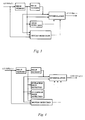
- Figure 3 shows a block diagram of a known motion adaptive IPC method in which an interlaced PAL signal is converted to a non-interlaced one. It uses two field memories, an interpolator block, edge detector and a motion detector. At moving locations interpolation is done spatially according to the edge information calculated by the edge detector, and in static locations interpolation is done temporally by copying the pixel from the preceding field.
- the edge information may be formed e.g. with a method according to the patent application FI-916195 (corresponding to EP-A-550231), but another intra-field method will also do. In this case, the interpolation of static locations requires no additional information, and it is done temporally in a fixed manner with pixel repetition, for example.
- Figure 4 is a block diagram of an NDHD (normal to high definition) conversion. It is an improved version of the arrangement according to Figure 3 presented in the patent application FI-923808 (corresponding to EP-A-584662), including now both motion detection and edge detections - one for moving and one for static regions.
- the edge detection and interpolation for static regions may be performed e.g. with a method according to the patent application FI-921676 (corresponding to EP-A-565948); correspondingly, the method of the patent application FI-923808 is suitable for moving regions.
- Another method comprising both motion detection and edge detection is disclosed in the publication of IEEE Transactions on Consumer Electronics, vol. 39, no. 3, August 1993, NY, US, pages 234-240 : "A deinterlacer for IQTV receivers and multimedia applications" by R. Simonetti et al.
- a difference signal across an image which defines the minimum motion region is expanded horizontally using edge information calculated from two successive fields.
- the edge detector is based on a thresholded difference signal between successive odd or even-numbered fields defining the minimum motion region, and on a controlled horizontal expansion of the minimum motion region according to horizontal edges. Indefinite motion regions are smoothed in the motion information post-processing.
- the method comprises the following phases:
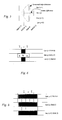
- the pixel value in one position is changed after a time the duration of which corresponds to the image frequency.
- it is calculated for all samples the above-mentioned frame difference signal, and it is found the locations in which the signal exceeds a preset threshold value kl. These positions will be interpreted moving and they are called moving pixels (moving_pixel).
- a mathematical expression for the first phase is: if
- ⁇ k 1 , then m(x,y,t) moving_pixel, where s(x,y,t) is the luminance value of the pixel in field t, line y, position x, and m(x,y,t) is the motion information associated with this pixel.
- a suitable threshold value k 1 is about 12.
- edge_pixel edge pixels
- the cross detection mask shown in Figure 6 is used as detector. Samples from the same horizontal position from two successive lines y-1 and y+1 in field t are taken to the top and bottom rows of the mask, each comprising one sample location. To the middle row it is taken three successive samples of the previous field t-1 swept between these lines, the middlemost of which has the same horizontal position as the samples in the top and bottom rows of the cross.
- the detector With the detector it is found the maximum for the values: the difference of the top and middle samples in the window, the difference of the middle and bottom samples in the window. From the maximum value it is subtracted the difference of the maximum sample and minimum sample in the middle row. The result is marked hor_value. If this value exceeds a preset threshold value k 2 , it is interpreted an edge pixel.
- hor _ value max[
- ] - range[ s ( x -1, y , t -1), s ( x, y , t -1), s ( x +1, y , t -1)] if ( hor _ value ⁇ k 2 ) then e ( x, y , t ) edge_pixel , where
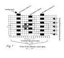
- the third phase is to expand the motion region. It is expanded according to the moving and edge pixels.
- the expansion is described with reference to Figure 7.
- count edge_pixel If simultaneously the number of moving pixels and the number of edge pixels in the region is greater than 1, the pixel is considered moving.
- a suitable value for v is about 15 and for u, about 2.
- a question mark marks the location the motion information of which is to be examined.
- the bar is in the left, at the location x-6/x-5, and it moves to the right, and is during the field (t+1) at the location x+6/x+7.
- These locations are well detected by means of the difference signal, and they have been marked as moving pixels.
- the edge pixels have been examined by means of an operator according to Figure 6, and it has been observed that there is an edge pixel at the location x/x+1. Then the motion region can be expanded by connecting it to the edge pixels.
- the critical value is v , which indicates how far motion is searched for.
- v indicates how far motion is searched for.
- movement greater than 15 pixels/field is rare, and that is why it has been selected as limit.
- v it is controlled how quick a movement it is possible to detect but also how wide the region in which incorrect detection may occur.
- Motion information like other control information, must generally be improved, or post-processed. That means filling out single holes or removing single pixels.
- the post-processing it is examined regions of a selected size, e.g. 5x3 regions.
- Post-filtering of the motion detection described above is done on three successive lines of one field; in the figure, on successive lines y-2, y, y+2 of field t.
- the window the size of which may be e.g. 5*3, it is examined how many moving pixels there are in it. If there are less moving pixels than the preset condition, then the middlemost pixel in the window is considered not moving. If, in the case presented by Figure 8, in which there are 15 samples in the window, there are e.g. three or less moving pixels, then the middlemost pixel examined is not moving.
- Post-processing done in a 5*3 window can thus be divided into the following phases:
- location x,y can be considered a moving pixel.
- Phase 2 of this post-filtering improves the noise tolerance of the system and reduces coupling errors.
- phase 3 all one-line-high moving lines are converted into non-moving. This reduces expansion of the motion region into static regions. It should also be noted that the processing mentioned above expands the motion region always when the conditions are met and location x,y was not originally a moving pixel.
- the detection of a horizontal edge may be performed in a way different from the one presented here. It may be done in the way shown in the patent application FI-921676, which deals with an application similar to the one illustrated in Figure 4, or another known edge detector, say, a Sobel detector, may be used for it.
- post-processing can be done in a way different from the one discussed above, but yet in a manner such that all single moving lines are converted into static ones.
- All threshold values are selectable and it is possible to make them adaptively controlled.
Landscapes
- Engineering & Computer Science (AREA)
- Computer Graphics (AREA)
- Multimedia (AREA)
- Signal Processing (AREA)
- Television Systems (AREA)
Claims (7)
- Procédé permettant de détecter le mouvement dans un signal vidéo numérique entrelacé, avec lequel on recueille des informations pour savoir s'il se produit un mouvement dans le champ (t), à l'emplacement (x,y,t) étudié d'une nouvelle ligne (y) générée entre deux lignes (y-1, y+1) successives suivant la direction verticale, caractérisé en ce que pour chaque emplacement (x,y,t) étudié :a) on calcule le signal différentiel entre le pixel du champ précédent (t-1) à la position (x,y) de l'emplacement étudié et le pixel du champ suivant (t+1) à la position (x,y) de l'emplacement étudié, et le signal différentiel est comparé à une première valeur de seuil préréglée (x,y) et si le signal différentiel excède la première valeur de seuil, l'emplacement (x,y,t) étudié est appelé pixel animé,b) on trouve dans l'image constituant le champ (t) et le champ précédent (t-1) les emplacements des bords horizontaux et, s'il y a un bord situé à l'emplacement (x,y,t) étudié, l'emplacement est appelé pixel de bord,c) on compte dans une première région (x-v, ..., x+v) le nombre de pixels animés sur la nouvelle ligne (y) générée et, dans une seconde région (x-u, ...,x+u), le nombre de pixels de bord, et si le nombre de pixels animés et le nombre de pixels de bord sont simultanément supérieurs à une seconde valeur de seuil préréglée, on estime qu'il existe un mouvement associé à l'emplacement (x,y,t) étudié.
- Procédé selon la revendication 1, caractérisé en ce que la première valeur de seuil est environ 12.
- Procédé selon la revendication 1, caractérisé en ce que les emplacements de bord horizontaux situés à l'emplacement (x,y,t) étudié sont déterminés en calculant la valeur HOR suivante :et si la valeur HOR est supérieure à une troisième valeur de seuil préréglée, l'emplacement étudié est appelé pixel de bord.dans laquelle max [ ] représente le maximum d'entrées,plage [ ] représente la différence du maximum et du minimum d'entrées,
- Procédé selon la revendication 3, caractérisé en ce que la troisième valeur de seuil est environ 8.
- Procédé selon la revendication 1, caractérisé en ce que la première région comprend 15 emplacements et la seconde en comprend 2 des deux côtés de l'emplacement (x,y,t) étudié et en ce que la seconde valeur de seuil est égale à 1.
- Procédé selon la revendication 1, caractérisé en ce que, lorsque les informations de mouvement ont été recueillies pour chaque emplacement (x,y,t) étudié, on procède à un post-traitement dans lequel les informations de mouvement de l'emplacement étudié sont comparées aux informations de mouvement des emplacements étudiés dans le voisinage.
- Procédé selon la revendication 6, caractérisé en ce que 3 nouvelles lignes successives sont amenées simultanément à une fenêtre M*3, M éléments d'informations de mouvement associés à des emplacements successifs d'une ligne se trouvant à ce moment-là, sur chaque rangée de la fenêtre, et en ce que les informations finales de mouvement de l'emplacement (x,y,t) étudié au centre de la fenêtre sont déterminées comme suit : on calcule combien d'emplacements sur chaque rangée de la fenêtre indiquent un mouvement associé à l'emplacement, on calcule le nombre d'emplacements de la fenêtre auxquels un mouvement est associé et si le nombre est égal à 0 ou à 1 ou si le nombre est M sur une rangée, on estime alors qu'aucun mouvement n'est associé à l'emplacement (x,y,t) étudié.
Applications Claiming Priority (2)
| Application Number | Priority Date | Filing Date | Title |
|---|---|---|---|
| FI942751A FI97663C (fi) | 1994-06-10 | 1994-06-10 | Menetelmä liikkeen tunnistamiseksi videosignaalista |
| FI942751 | 1994-06-10 |
Publications (3)
| Publication Number | Publication Date |
|---|---|
| EP0687105A2 EP0687105A2 (fr) | 1995-12-13 |
| EP0687105A3 EP0687105A3 (fr) | 1996-01-17 |
| EP0687105B1 true EP0687105B1 (fr) | 1998-03-04 |
Family
ID=8540896
Family Applications (1)
| Application Number | Title | Priority Date | Filing Date |
|---|---|---|---|
| EP95108075A Expired - Lifetime EP0687105B1 (fr) | 1994-06-10 | 1995-05-26 | Procédé pour détecter le mouvement dans un signal vidéo |
Country Status (3)
| Country | Link |
|---|---|
| EP (1) | EP0687105B1 (fr) |
| DE (1) | DE69501682D1 (fr) |
| FI (1) | FI97663C (fr) |
Families Citing this family (9)
| Publication number | Priority date | Publication date | Assignee | Title |
|---|---|---|---|---|
| EP0946055B1 (fr) | 1998-03-09 | 2006-09-06 | Sony Deutschland GmbH | Méthode et système d'interpolation de signaux numériques |
| JP2003530028A (ja) | 2000-03-31 | 2003-10-07 | コーニンクレッカ フィリップス エレクトロニクス エヌ ヴィ | テキスト検出 |
| TWI227085B (en) | 2003-11-13 | 2005-01-21 | Realtek Semiconductor Corp | Method and apparatus for detecting sawtooth and field motion |
| CN100426833C (zh) * | 2003-12-16 | 2008-10-15 | 瑞昱半导体股份有限公司 | 一种检测影像信号的方法与相关装置 |
| WO2006013510A1 (fr) * | 2004-07-29 | 2006-02-09 | Koninklijke Philips Electronics N.V. | Desentrelacement |
| TWI325273B (en) | 2006-08-16 | 2010-05-21 | Realtek Semiconductor Corp | Method and apparatus for detecting sawtooth and field motion |
| CN101527785B (zh) * | 2008-03-06 | 2011-04-06 | 瑞昱半导体股份有限公司 | 图像位移检测方法及相关装置 |
| CN101808188B (zh) * | 2009-02-12 | 2012-08-08 | 瑞昱半导体股份有限公司 | 图像处理装置与图像处理方法 |
| US10497282B1 (en) | 2018-10-31 | 2019-12-03 | International Business Machines Corporation | Physical movement simulation on a display device |
Family Cites Families (3)
| Publication number | Priority date | Publication date | Assignee | Title |
|---|---|---|---|---|
| KR950000440B1 (ko) * | 1991-12-27 | 1995-01-19 | 주식회사 금성사 | 티브이 신호의 주사선 수 2배 증가방법 및 회로 |
| FI89995C (fi) * | 1991-12-31 | 1993-12-10 | Salon Televisiotehdas Oy | Foerfarande foer randadaptiv interpolation av en tv-bilds linje samt en interpolator |
| FI91029C (fi) * | 1992-04-14 | 1994-04-25 | Salon Televisiotehdas Oy | Menetelmä ja kytkentäjärjestely kuvaruudulla näytettävän kuvan pysty- ja vaakaresoluution kaksinkertaistamiseksi |
-
1994
- 1994-06-10 FI FI942751A patent/FI97663C/fi active
-
1995
- 1995-05-26 EP EP95108075A patent/EP0687105B1/fr not_active Expired - Lifetime
- 1995-05-26 DE DE69501682T patent/DE69501682D1/de not_active Expired - Lifetime
Also Published As
| Publication number | Publication date |
|---|---|
| EP0687105A2 (fr) | 1995-12-13 |
| EP0687105A3 (fr) | 1996-01-17 |
| FI97663B (fi) | 1996-10-15 |
| FI942751A0 (fi) | 1994-06-10 |
| FI97663C (fi) | 1997-01-27 |
| FI942751L (fi) | 1995-12-11 |
| DE69501682D1 (de) | 1998-04-09 |
Similar Documents
| Publication | Publication Date | Title |
|---|---|---|
| US6262773B1 (en) | System for conversion of interlaced video to progressive video using edge correlation | |
| US6118488A (en) | Method and apparatus for adaptive edge-based scan line interpolation using 1-D pixel array motion detection | |
| US20060146187A1 (en) | Adaptive interlace-to-progressive scan conversion algorithm | |
| EP1313310A2 (fr) | Méthode de conversion entrelacé-progressif d'un format vidéo avec faible latence | |
| KR20040009967A (ko) | 디인터레이싱장치 및 방법 | |
| JP2002523985A (ja) | 画像信号における問題領域位置決め | |
| EP1101354B1 (fr) | Conversion de signaux-image entrelaces en signaux-image balayees progressivement par scanner | |
| JPH07162811A (ja) | 中間フィールドまたは中間フレームの動き補償内挿方法および装置 | |
| EP0687105B1 (fr) | Procédé pour détecter le mouvement dans un signal vidéo | |
| EP1444837B1 (fr) | Procede et dispositif de detection d'occlusions | |
| KR100768579B1 (ko) | 주사 변환 장치 | |
| EP0540347A2 (fr) | Circuit de détection de mouvement pour un signal d'image de télévision à haute résolution basé sur le système muse | |
| Lee et al. | A motion-adaptive deinterlacer via hybrid motion detection and edge-pattern recognition | |
| JP3745425B2 (ja) | 動きベクトル検出方法および動きベクトル検出用適応切り替え型前置フィルタ | |
| EP0517385B1 (fr) | Méthode de doublement de nombre de lignes d'un signal vidéo reçu sous la forme d'échantillons successifs | |
| EP0584662B1 (fr) | Méthode et appareil pour doubler la fréquence horizontale et verticale d'un signal vidéo | |
| JPH0779417A (ja) | 動き補正ビデオ信号処理方式 | |
| Lee et al. | Motion detection and motion adaptive pro-scan conversion | |
| EP0648046A2 (fr) | Méthode et dispositif pour interpoler avec compensation de mouvement des champs ou des trames intermédiaires | |
| JPS61141286A (ja) | テレビジヨン信号の走査変換装置 | |
| JPH0715700A (ja) | 動き補正映像信号処理装置及び方法 | |
| JP2000078535A (ja) | 順次走査変換装置及び方法 | |
| JP3721941B2 (ja) | 走査線補間装置 | |
| Pelagotti et al. | High quality video on multimedia PCs | |
| JPH04372292A (ja) | 動きベクトル検出装置 |
Legal Events
| Date | Code | Title | Description |
|---|---|---|---|
| PUAI | Public reference made under article 153(3) epc to a published international application that has entered the european phase |
Free format text: ORIGINAL CODE: 0009012 |
|
| PUAL | Search report despatched |
Free format text: ORIGINAL CODE: 0009013 |
|
| AK | Designated contracting states |
Kind code of ref document: A2 Designated state(s): DE FR GB IT |
|
| AK | Designated contracting states |
Kind code of ref document: A3 Designated state(s): DE FR GB IT |
|
| 17P | Request for examination filed |
Effective date: 19960212 |
|
| GRAG | Despatch of communication of intention to grant |
Free format text: ORIGINAL CODE: EPIDOS AGRA |
|
| GRAG | Despatch of communication of intention to grant |
Free format text: ORIGINAL CODE: EPIDOS AGRA |
|
| GRAH | Despatch of communication of intention to grant a patent |
Free format text: ORIGINAL CODE: EPIDOS IGRA |
|
| 17Q | First examination report despatched |
Effective date: 19970725 |
|
| GRAH | Despatch of communication of intention to grant a patent |
Free format text: ORIGINAL CODE: EPIDOS IGRA |
|
| GRAA | (expected) grant |
Free format text: ORIGINAL CODE: 0009210 |
|
| AK | Designated contracting states |
Kind code of ref document: B1 Designated state(s): DE FR GB IT |
|
| PG25 | Lapsed in a contracting state [announced via postgrant information from national office to epo] |
Ref country code: IT Free format text: LAPSE BECAUSE OF FAILURE TO SUBMIT A TRANSLATION OF THE DESCRIPTION OR TO PAY THE FEE WITHIN THE PRESCRIBED TIME-LIMIT;WARNING: LAPSES OF ITALIAN PATENTS WITH EFFECTIVE DATE BEFORE 2007 MAY HAVE OCCURRED AT ANY TIME BEFORE 2007. THE CORRECT EFFECTIVE DATE MAY BE DIFFERENT FROM THE ONE RECORDED. Effective date: 19980304 Ref country code: FR Free format text: LAPSE BECAUSE OF FAILURE TO SUBMIT A TRANSLATION OF THE DESCRIPTION OR TO PAY THE FEE WITHIN THE PRESCRIBED TIME-LIMIT Effective date: 19980304 |
|
| REF | Corresponds to: |
Ref document number: 69501682 Country of ref document: DE Date of ref document: 19980409 |
|
| PG25 | Lapsed in a contracting state [announced via postgrant information from national office to epo] |
Ref country code: DE Free format text: LAPSE BECAUSE OF FAILURE TO SUBMIT A TRANSLATION OF THE DESCRIPTION OR TO PAY THE FEE WITHIN THE PRESCRIBED TIME-LIMIT Effective date: 19980605 |
|
| EN | Fr: translation not filed | ||
| PLBE | No opposition filed within time limit |
Free format text: ORIGINAL CODE: 0009261 |
|
| STAA | Information on the status of an ep patent application or granted ep patent |
Free format text: STATUS: NO OPPOSITION FILED WITHIN TIME LIMIT |
|
| 26N | No opposition filed | ||
| PG25 | Lapsed in a contracting state [announced via postgrant information from national office to epo] |
Ref country code: GB Free format text: LAPSE BECAUSE OF NON-PAYMENT OF DUE FEES Effective date: 19990526 |
|
| GBPC | Gb: european patent ceased through non-payment of renewal fee |
Effective date: 19990526 |