EP0687107B1 - Fernsehempfänger, der eine Videoaufnahme-/Wiedergabe-Einrichtung enthält - Google Patents
Fernsehempfänger, der eine Videoaufnahme-/Wiedergabe-Einrichtung enthält Download PDFInfo
- Publication number
- EP0687107B1 EP0687107B1 EP95303855A EP95303855A EP0687107B1 EP 0687107 B1 EP0687107 B1 EP 0687107B1 EP 95303855 A EP95303855 A EP 95303855A EP 95303855 A EP95303855 A EP 95303855A EP 0687107 B1 EP0687107 B1 EP 0687107B1
- Authority
- EP
- European Patent Office
- Prior art keywords
- colour system
- circuit
- colour
- automatic
- discriminating
- Prior art date
- Legal status (The legal status is an assumption and is not a legal conclusion. Google has not performed a legal analysis and makes no representation as to the accuracy of the status listed.)
- Expired - Lifetime
Links
Images


Classifications
-
- H—ELECTRICITY
- H04—ELECTRIC COMMUNICATION TECHNIQUE
- H04N—PICTORIAL COMMUNICATION, e.g. TELEVISION
- H04N9/00—Details of colour television systems
- H04N9/79—Processing of colour television signals in connection with recording
-
- H—ELECTRICITY
- H04—ELECTRIC COMMUNICATION TECHNIQUE
- H04N—PICTORIAL COMMUNICATION, e.g. TELEVISION
- H04N5/00—Details of television systems
- H04N5/44—Receiver circuitry for the reception of television signals according to analogue transmission standards
- H04N5/46—Receiver circuitry for the reception of television signals according to analogue transmission standards for receiving on more than one standard at will
Definitions
- the invention relates to a television receiver incorporating a video recording and reproducing apparatus capable of discriminating and receiving two or more different television standard system such as NTSC, PAL, and SECAM, and recording and reproducing the video signals, and more particularly to a television receiver incorporating a video recording and reproducing apparatus comprising two or more automatic color system discriminating circuits differing in the discriminating capacity for discriminating different television standard systems.
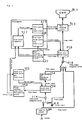
- FIG. 1 A conventional example of television receiving incorporating a video recording and reproducing apparatus comprising an automatic color system discriminating system is shown in Fig. 1.
- an output video signal from a tuner IF circuit 101 integrating a tuner for receiving input television signals from an antenna and an IF circuit for converting received signals into intermediate frequency and amplifying, or a video signal from an video signal input terminal 116 is selected by a video signal changeover switch 114 and a video signal changeover switch 113, and is fed into a second color system circuit 102 and a first color system circuit 106.
- the video signal fed into the second color system circuit 102 is branched, and added to a second automatic color system discriminating circuit 103, and a second color system control data output circuit 105 is controlled by the information of the color system discriminated by the second automatic color system discriminating circuit 103, the color system corresponding to the standard system of the input video signal is set by the second color system circuit 102 on the basis of the control signal generated in this circuit, and the output of the second color system circuit 102 is recorded in a video recording and reproducing apparatus (for example, video tape recorder) 104.
- a video recording and reproducing apparatus for example, video tape recorder
- the video signal fed into the first color system circuit 106 is branched, and added to a first automatic color system discriminating circuit 107, and the information of the color system discriminated by the first automatic color system discriminating circuit 107 is added to a first color system control data output circuit 109 as control signal, the color system corresponding to the standard system of the input video signal is set in the first color system circuit 106 on the basis of the control signal of the first color system control data output circuit 109, its output is fed into an adjusting circuit 110 of a color for adjusting the color on the basis of the control signal of a control data output circuit 115 of color, and it is reproduced on the CRT 111 after color adjustment.
- the color system of the video signal entered at this time may be discriminated in the first automatic color system discriminating circuit 107 but not discriminated in the second automatic color system discriminating circuit 103 due to difference in the discriminating capacity. If discriminated, nevertheless, the television circuit for issuing to the CRT generally contains a deflection circuit, and the result of discrimination is accurately reflected in the output video signal easily, but setting of color system tends to be improper at the color system circuit 102 side of the video recording and reproducing apparatus, and the video signal produced from the color system circuit 102 is often stored in the video recording and reproducing apparatus 104 as a picture of abnormal colour (for example, colourless).
- abnormal colour for example, colourless
- the video signal reproduced from thus recorded video recording and reproducing apparatus 104 is reproduced in the CRT 111 directly as picture of abnormal colour.
- a first aspect of the television receiver incorporating a video recording and reproducing apparatus of the invention comprises:
- the color system comparator compares the color system information judged by the first automatic color system discriminating circuit and the color system information discriminated by the second automatic color system discriminating circuit, and issues a control signal when it is judged impossible to discriminate by the second automatic color system judging circuit.
- the color adjusting circuit is adjusted in the color control data output circuit, and accordingly the color of the CRT is adjusted, and it functions to show abnormal picture when recording the picture by showing a wrong color from the display device to the user.
- the user when the user records the picture in the video recording and reproducing apparatus, it gives a warning so that abnormal color may not be recorded due to impossibility to discriminate the color system in the second automatic color system discriminating circuit, so that the user can set proper processing beforehand.
- Fig. 2 is a block diagram of a television receiver incorporating video recording and reproducing apparatus in a first embodiment of the invention.
- a comparison output of a color system comparator 217 is given to a color control data output circuit 215, and its output is given to a color adjusting circuit 210, where the color of a first color system circuit 206 is adjusted and issued to a CRT 211.
- a first color system control data output circuit 209, a color system comparator 217, and color control data output circuit 215 may be composed of microcomputers, and other constituent parts may be also processed on the software of microcomputer.
- the output video signal of the tuner IF circuit 201 for receiving and amplifying the input television signal from the antenna, or a video signal from an video signal input terminal 216 is selected by a video signal changeover switch 214 and a video signal changeover switch 213, and is fed into a second color system circuit 202 and a first color system circuit 206.
- the video signal fed into the second color system circuit 202 is branched, and added to a second automatic color system discriminating circuit 203, and a second color system control data output circuit 205 is controlled by the information of the color system discriminated by the second automatic color system discriminating circuit 203, the color system corresponding to the standard system of the input video signal is set by the second color system circuit 202 on the basis of the control signal generated in this circuit, and fed, recorded and reproduced in a video recording and reproducing apparatus (for example, video tape recorder) 204.
- a video recording and reproducing apparatus for example, video tape recorder
- the output of the video changeover switch 213 for changing over the video signal from the tuner IF circuit 201, the video signal from the video signal input terminal 216, and the video signal from the video recording and reproducing apparatus 204 is added to the first color system circuit 206, and this input video signal is branched, and added to a first automatic color system discriminating circuit 207.
- the first color system control data output circuit 209 is controlled, and the color system is set according to the standard system of the input video signal in the first color system circuit 206 on the basis of the control signal of the first color system control data output circuit 209.
- the color system When setting of the color system is automatic, the color system is set by the information of the color system discriminated by the second automatic color system discriminating circuit 203 and first automatic color system discriminating circuit 207.
- color system information 218 information of the system that cannot be discriminated by the second automatic color system discriminating circuit 203 is accumulated, for example, in a memory.
- the information of the color system discriminated in the first automatic color system discriminating circuit 207 is also given to a color system comparator 217.
- This information and the color system information held in color system information means 218 are compared in the color system comparator 217, and when the result of comparison is same, it is judged that it cannot be discriminated correctly in the second automatic color system discriminating circuit 203.
- the data that can be discriminated in the second automatic color system discriminating circuit 203 may be held. In such a case, if not same as the result judged by the color system comparator 217, it is judged that it cannot be discriminated correctly in the second automatic color system discriminating circuit 203.
- a control signal is generated from a color control data output circuit 215, and it is fed into a color adjusting circuit 210 for adjusting the video signal color entered from the first color system circuit 206, and herein the color adjusting circuit 210 is adjusted so that the color may be in abnormal state, for example, in colorless state.
- a colorless video signal is reproduced in a CRT 211 which is a display device, and the user knows that the video information produced from the second color system circuit 202 and entered into the video recording and reproducing apparatus 204 is to be recorded as a signal of abnormal color (for example, colorless), so that the user can either adjust correctly the color of the signal to be recorded in the video recording and reproducing apparatus 204 by adjusting the second color system circuit 202 or the like, or, if impossible to adjust, stop recording into the video recording and reproducing apparatus 204.
- a signal of abnormal color for example, colorless
- Fig. 3 is a block diagram of a television receiver incorporating a video recording and reproducing apparatus in a second embodiment of the invention.
- the color system comparator 217 the information of color system discriminated in the first automatic color system discriminating circuit 207 and the information of color system discriminated in the second automatic color system discriminating circuit 203 are compared, and when the result of comparison is different, the color system comparator 217 judges that it cannot be discriminated correctly in the second automatic color system discriminating circuit 203, while the other operation is same as in the first embodiment and is not explained herein.
- the color control data output circuit 215 is operated, and the color adjusting circuit 210 is controlled so that the video signal entered from the first color system circuit 206 may not be colored.
- a colorless video signal is reproduced in the CRT 211.
- the user knows that the video information produced from the second color system circuit 202 and entered into the video recording and reproducing apparatus 204 is to be recorded as a signal of abnormal color (for example, colorless), so that the user can adjust correctly the color of the signal to be recorded in the video recording and reproducing apparatus 204 by adjusting the second color system circuit 202 or the like, same as in the first embodiment.
- a signal of abnormal color for example, colorless
- the discriminating capacity differs between the first automatic color system discriminating circuit for sending the video signal into the CRT, and the second automatic color system discriminating circuit for sending the video signal to the video recording and reproducing apparatus, in order to avoid the problem of abnormal reproduced image in the video recording and reproducing apparatus in spite of normal display in the CRT as the display device, or failure in video recording while not knowing that the automatic color system discriminating circuit for sending the video signal to the video recording and reproducing circuit cannot discriminate the input video signal, the fact of abnormality of the video signal to be recorded can be shown to the user through the CRT before recording the video signal in the video recording and reproducing apparatus.
- the display device is not limited to the CRT, but any means capable of reproducing the television may be used.
Landscapes
- Engineering & Computer Science (AREA)
- Multimedia (AREA)
- Signal Processing (AREA)
- Processing Of Color Television Signals (AREA)
- Color Television Systems (AREA)
- Testing, Inspecting, Measuring Of Stereoscopic Televisions And Televisions (AREA)
- Television Signal Processing For Recording (AREA)
- Color Image Communication Systems (AREA)
- Facsimile Image Signal Circuits (AREA)
- Image Processing (AREA)
Claims (5)
- Fernsehempfänger, der eine Video-Aufzeichnungs-und-Wiedergabe-Vorrichtung einschließt, und der umfasst:eine erste automatische Farbsystem-Erkennungsschaltung (207), die ein Farbsystem eines Eingangsvideosignal erkennt,eine erste Farbsystemsteuerdaten-Ausgangsschaltung (209), die Farbsystemsteuerdaten an eine erste Farbsystemschaltung (206) auf der Grundlage der Feststellung beim Erkennen des Farbsystems durch die erste automatische Farbsystem-Erkennungsschaltung anlegt und das Farbsystem einstellt,eine zweite automatische Farbsystem-Erkennungsschaltung (203), die das Farbsystem des Eingangsvideosignals erkennt,eine zweite Farbsystemsteuerdaten-Ausgangsschaltung (205), die Farbsystemsteuerdaten an eine zweite Farbsystemschaltung auf der Grundlage der Feststellung beim Erkennen des Farbsystems durch die zweite automatische Farbsystem-Erkennungsschaltung anlegt und das Farbsystem einstellt, undeine Video-Aufzeichnungs-und-Wiedergabe-Vorrichtung (204), die ein Ausgangsvideosignal der zweiten Farbsystemschaltung aufzeichnet,wobei der Empfänger dadurch gekennzeichnet ist, dass er des Weiteren umfasst:eine Farbsystem-Informationseinrichtung (218), die Farbsysteminformationen speichert, wobei die Informationen genutzt werden, um Zustimmung oder Ablehnung der Erkennung des Farbsystems durch die zweite automatische Farbsystem-Erkennungsschaltung festzustellen;eine Farbsystem-Vergleichseinrichtung (217), die die Farbsystemerkennung durch die erste automatische Farbsystem-Erkennungsschaltung mit den Farbsysteminformationen vergleicht, die in der Farbsystem-Informationseinrichtung gespeichert sind, und ein Steuersignal ausgibt, wenn der Vergleich zeigt, dass es unmöglich ist, das Farbsystem in der zweiten automatischen Farbsystem-Erkennungsschaltung zu erkennen;eine Farbregulierschaltung (210), die die Farbe des Ausgangs der ersten Farbsystemschaltung reguliert;eine zweite Farbsteuerdaten-Ausgangsschaltung (215), die das Steuersignal der Farbsystem-Vergleichseinrichtung empfängt und die Farbregulierschaltung in Reaktion darauf steuert; undeine Anzeigevorrichtung (211), die den Ausgang der Farbregulierschaltung empfängt und ein Bild daraus wiedergibt.
- Fernsehempfänger, der eine Video-Aufzeichnungs-und-Wiedergabe-Vorrichtung einschließt und der umfasst:eine erste automatische Farbsystem-Erkennungsschaltung (207), die ein Farbsystem eines Eingangsvideosignals erkennt,eine erste Farbsystemsteuerdaten-Ausgangsschaltung (209), die Farbsystemsteuerdaten an eine erste Farbsystemschaltung (206) auf der Grundlage der Feststellung beim Erkennen des Farbsystems durch die erste automatische Farbsystem-Erkennungsschaltung anlegt und das Farbsystem einstellt,eine zweite automatische Farbsystem-Erkennungsschaltung (203), die das Farbsystem des Eingangsvideosignals erkennt,eine zweite Farbsystemsteuerdaten-Ausgangsschaltung (205), die Farbsystemsteuerdaten an eine zweite Farbsystemschaltung auf der Grundlage des Feststellens beim Erkennen des Farbsystems durch die zweite automatische Farbsystem-Erkennungsschaltung anlegt und das Farbsystem einstellt, undeine Video-Aufzeichnungs-und-Wiedergabe-Vorrichtung (204), die ein Ausgangsvideosignal der zweiten Farbsystemschaltung aufzeichnet,wobei der Empfänger dadurch gekennzeichnet ist, dass er des Weiteren umfasst:eine Farbsystem-Vergleichseinrichtung (217), die die Farbsystemerkennung durch die erste automatische Farbsystem-Erkennungsschaltung und die Farbsystemerkennung durch die zweite automatische Farbsystem-Erkennungsschaltung vergleicht und ein Steuersignal ausgibt, wenn der Vergleich zeigt, dass die entsprechenden Erkennungen sich voneinander unterscheiden und es daher unmöglich ist, das Farbsystem in der zweiten automatischen Farbsystem-Erkennungsschaltung zu erkennen;eine Farbregulierschaltung (210), die die Farbe des Ausgangs der ersten Farbsystemschaltung reguliert;eine Farbsteuerdaten-Ausgangsschaltung (215), die das Steuersignal der Farbsystem-Vergleichseinrichtung empfängt und die Farbregulierschaltung in Reaktion darauf steuert; undeine Anzeigevorrichtung (211), die den Ausgang der Farbregulierschaltung empfängt und ein Bild daraus wiedergibt.
- Fernsehempfänger, der eine Video-Aufzeichnungs-und-Wiedergabe-Vorrichtung einschließt, nach Anspruch 1, wobei die Farbsystem-Informationseinrichtung die Farbsysteminformationen speichert, die von der zweiten automatischen Farbsystem-Erkennungsschaltung nicht erkannt werden können.
- Fernsehempfänger, der eine Video-Aufzeichnungs-und-Wiedergabe-Vorrichtung einschließt, nach Anspruch 1, wobei die Farbsystem-Informationseinrichtung die Farbsysteminformationen speichert, die von der zweiten automatischen Farbsystem-Erkennungsschaltung erkannt werden können.
- Fernsehempfänger, der eine Video-Aufzeichnungs-und-Wiedergabe-Vorrichtung einschließt, nach Anspruch 1 oder 2, wobei die Farbsystem-Vergleichseinrichtung ein Steuersignal zu der Farbsteuerdaten-Ausgangsschaltung sendet, so dass das Videosignal von der Farbregulierschaltung möglicherweise nicht farbig ist, wenn die zweite automatische Farbsystem-Erkennungsschaltung das Farbsystem nicht erkennen kann.
Applications Claiming Priority (3)
| Application Number | Priority Date | Filing Date | Title |
|---|---|---|---|
| JP12506994A JP3391554B2 (ja) | 1994-06-07 | 1994-06-07 | ビデオ内蔵型テレビジョン受像機 |
| JP125069/94 | 1994-06-07 | ||
| JP12506994 | 1994-06-07 |
Publications (3)
| Publication Number | Publication Date |
|---|---|
| EP0687107A2 EP0687107A2 (de) | 1995-12-13 |
| EP0687107A3 EP0687107A3 (de) | 1996-07-31 |
| EP0687107B1 true EP0687107B1 (de) | 2001-08-22 |
Family
ID=14901059
Family Applications (1)
| Application Number | Title | Priority Date | Filing Date |
|---|---|---|---|
| EP95303855A Expired - Lifetime EP0687107B1 (de) | 1994-06-07 | 1995-06-06 | Fernsehempfänger, der eine Videoaufnahme-/Wiedergabe-Einrichtung enthält |
Country Status (7)
| Country | Link |
|---|---|
| US (1) | US5570196A (de) |
| EP (1) | EP0687107B1 (de) |
| JP (1) | JP3391554B2 (de) |
| KR (1) | KR100201023B1 (de) |
| CN (1) | CN1086092C (de) |
| DE (1) | DE69522264T2 (de) |
| TW (1) | TW410523B (de) |
Families Citing this family (7)
| Publication number | Priority date | Publication date | Assignee | Title |
|---|---|---|---|---|
| US5940572A (en) * | 1996-11-27 | 1999-08-17 | Daewoo Electronics Co. Ltd. | Integrated television and video cassette recorder system |
| US6011592A (en) * | 1997-03-31 | 2000-01-04 | Compaq Computer Corporation | Computer convergence device controller for managing various display characteristics |
| JP3566546B2 (ja) * | 1998-04-01 | 2004-09-15 | Kddi株式会社 | 画像の品質異常検出方法および装置 |
| KR100514324B1 (ko) * | 1998-08-24 | 2005-11-30 | 삼성전자주식회사 | Tv수상기의 방송방식별 색포화도조정방법 |
| JP2003009160A (ja) * | 2001-06-27 | 2003-01-10 | Pioneer Electronic Corp | カラー方式判別装置およびカラー方式判別方法 |
| CN100366049C (zh) * | 2004-06-23 | 2008-01-30 | 南京Lg新港显示有限公司 | 电视机的输入信号处理装置及方法 |
| US20200000060A1 (en) * | 2018-06-28 | 2020-01-02 | James Scott Hayes | Chew toy made of solid rubber |
Family Cites Families (8)
| Publication number | Priority date | Publication date | Assignee | Title |
|---|---|---|---|---|
| GB1487406A (en) * | 1974-10-04 | 1977-09-28 | Matsushita Electric Industrial Co Ltd | Video recorders and receivers |
| AU606824B2 (en) * | 1988-12-23 | 1991-02-14 | Matsushita Electric Industrial Co., Ltd. | Video taperecorder with television standards converter |
| JPH02226296A (ja) * | 1989-02-28 | 1990-09-07 | Victor Co Of Japan Ltd | 高階調グラフィック画像伝送装置 |
| JP2771266B2 (ja) * | 1989-07-28 | 1998-07-02 | 株式会社日立製作所 | 多方式の映像信号の再生表示装置 |
| NL9000130A (nl) * | 1990-01-19 | 1990-05-01 | Philips Nv | Videosysteem. |
| JPH05130644A (ja) * | 1991-11-01 | 1993-05-25 | Hitachi Ltd | 画像処理用半導体集積回路装置 |
| KR950011655B1 (ko) * | 1992-10-31 | 1995-10-07 | 삼성전자주식회사 | 방송방식명 표시장치 |
| JPH07107397A (ja) * | 1993-09-29 | 1995-04-21 | Aiwa Co Ltd | テレビジョン受像機、記録装置および再生装置 |
-
1994
- 1994-06-07 JP JP12506994A patent/JP3391554B2/ja not_active Expired - Fee Related
-
1995
- 1995-05-01 TW TW084104317A patent/TW410523B/zh not_active IP Right Cessation
- 1995-06-05 US US08/462,612 patent/US5570196A/en not_active Expired - Fee Related
- 1995-06-06 DE DE69522264T patent/DE69522264T2/de not_active Expired - Fee Related
- 1995-06-06 EP EP95303855A patent/EP0687107B1/de not_active Expired - Lifetime
- 1995-06-07 KR KR1019950014893A patent/KR100201023B1/ko not_active Expired - Fee Related
- 1995-06-07 CN CN95106809A patent/CN1086092C/zh not_active Expired - Fee Related
Also Published As
| Publication number | Publication date |
|---|---|
| JP3391554B2 (ja) | 2003-03-31 |
| DE69522264T2 (de) | 2002-02-07 |
| US5570196A (en) | 1996-10-29 |
| KR100201023B1 (ko) | 1999-06-15 |
| DE69522264D1 (de) | 2001-09-27 |
| CN1114487A (zh) | 1996-01-03 |
| EP0687107A3 (de) | 1996-07-31 |
| EP0687107A2 (de) | 1995-12-13 |
| TW410523B (en) | 2000-11-01 |
| JPH07336724A (ja) | 1995-12-22 |
| CN1086092C (zh) | 2002-06-05 |
| KR960003330A (ko) | 1996-01-26 |
Similar Documents
| Publication | Publication Date | Title |
|---|---|---|
| KR100391405B1 (ko) | 입력기기선택방법 | |
| US4751581A (en) | Control system having a plurality of control command sources | |
| US5598278A (en) | System configuration method for audio-video apparatus with digital bus interface | |
| US5204662A (en) | Monitor television apparatus | |
| EP0687107B1 (de) | Fernsehempfänger, der eine Videoaufnahme-/Wiedergabe-Einrichtung enthält | |
| US4841367A (en) | Video source selecting system | |
| KR100191093B1 (ko) | 영상 신호 처리 장치 | |
| US20020135684A1 (en) | Method of switching between video signals in an image switching apparatus | |
| US5608535A (en) | Video signal reproduction or record/reproduction apparatus | |
| KR100732670B1 (ko) | 동작상태에 따른 외부기기 제어신호를 출력하는디브이디피와 브이씨알의 콤비네이션 시스템 | |
| US20070147783A1 (en) | Combination system and copy error preventing method thereof | |
| EP0608048B1 (de) | Vorrichtung und Verfahren zur Auswahl von Signalleitungen zur Verbindung mit einer Mehrzahl von Audio-Videogeräten | |
| US6310660B1 (en) | Video signal dropout detector | |
| KR0183814B1 (ko) | 텔레비젼과 비디오 카세트 레코더 일체형 시스템 및 그 동작 방법 | |
| US6285821B1 (en) | External input signal processing circuit for a television receiver with a video tape recorder for the purpose of viewing copy-protected video signals | |
| JP3016573B2 (ja) | ビデオテープレコーダの画像評価装置 | |
| US5606716A (en) | Device for detecting the connectivity of a monitor and inhibiting a data reproducing operation | |
| JP3168145B2 (ja) | 横長テレビ受信機の画面モード切換方法 | |
| JPS6321397B2 (de) | ||
| JP3093618B2 (ja) | 映像再生装置の制御システムおよび制御方法 | |
| KR100220100B1 (ko) | 비디오 카세트 레코더에서의 외부 연결단자 입/출력 절환방법 | |
| GB2252662A (en) | Video signal dubbing | |
| JP3116659B2 (ja) | 放送方式判別回路 | |
| KR100281843B1 (ko) | 보안용 브이 씨 알의 시간정보 녹화방법 | |
| KR100207663B1 (ko) | 영상기록재생장치의 재생방법 및 그에 적합한 장치 |
Legal Events
| Date | Code | Title | Description |
|---|---|---|---|
| PUAI | Public reference made under article 153(3) epc to a published international application that has entered the european phase |
Free format text: ORIGINAL CODE: 0009012 |
|
| AK | Designated contracting states |
Kind code of ref document: A2 Designated state(s): DE FR GB |
|
| PUAL | Search report despatched |
Free format text: ORIGINAL CODE: 0009013 |
|
| AK | Designated contracting states |
Kind code of ref document: A3 Designated state(s): DE FR GB |
|
| 17P | Request for examination filed |
Effective date: 19961114 |
|
| 17Q | First examination report despatched |
Effective date: 19990315 |
|
| GRAG | Despatch of communication of intention to grant |
Free format text: ORIGINAL CODE: EPIDOS AGRA |
|
| GRAG | Despatch of communication of intention to grant |
Free format text: ORIGINAL CODE: EPIDOS AGRA |
|
| GRAH | Despatch of communication of intention to grant a patent |
Free format text: ORIGINAL CODE: EPIDOS IGRA |
|
| GRAG | Despatch of communication of intention to grant |
Free format text: ORIGINAL CODE: EPIDOS AGRA |
|
| GRAH | Despatch of communication of intention to grant a patent |
Free format text: ORIGINAL CODE: EPIDOS IGRA |
|
| GRAH | Despatch of communication of intention to grant a patent |
Free format text: ORIGINAL CODE: EPIDOS IGRA |
|
| GRAA | (expected) grant |
Free format text: ORIGINAL CODE: 0009210 |
|
| AK | Designated contracting states |
Kind code of ref document: B1 Designated state(s): DE FR GB |
|
| REF | Corresponds to: |
Ref document number: 69522264 Country of ref document: DE Date of ref document: 20010927 |
|
| REG | Reference to a national code |
Ref country code: GB Ref legal event code: IF02 |
|
| ET | Fr: translation filed | ||
| PGFP | Annual fee paid to national office [announced via postgrant information from national office to epo] |
Ref country code: GB Payment date: 20020605 Year of fee payment: 8 |
|
| PGFP | Annual fee paid to national office [announced via postgrant information from national office to epo] |
Ref country code: FR Payment date: 20020610 Year of fee payment: 8 |
|
| PGFP | Annual fee paid to national office [announced via postgrant information from national office to epo] |
Ref country code: DE Payment date: 20020612 Year of fee payment: 8 |
|
| PLBE | No opposition filed within time limit |
Free format text: ORIGINAL CODE: 0009261 |
|
| STAA | Information on the status of an ep patent application or granted ep patent |
Free format text: STATUS: NO OPPOSITION FILED WITHIN TIME LIMIT |
|
| 26N | No opposition filed | ||
| PG25 | Lapsed in a contracting state [announced via postgrant information from national office to epo] |
Ref country code: GB Free format text: LAPSE BECAUSE OF NON-PAYMENT OF DUE FEES Effective date: 20030606 |
|
| PG25 | Lapsed in a contracting state [announced via postgrant information from national office to epo] |
Ref country code: DE Free format text: LAPSE BECAUSE OF NON-PAYMENT OF DUE FEES Effective date: 20040101 |
|
| GBPC | Gb: european patent ceased through non-payment of renewal fee |
Effective date: 20030606 |
|
| PG25 | Lapsed in a contracting state [announced via postgrant information from national office to epo] |
Ref country code: FR Free format text: LAPSE BECAUSE OF NON-PAYMENT OF DUE FEES Effective date: 20040227 |
|
| REG | Reference to a national code |
Ref country code: FR Ref legal event code: ST |