EP0687159B1 - Signaux hemodynamiques derives d'un detecteur de mouvement de la paroi cardiaque - Google Patents
Signaux hemodynamiques derives d'un detecteur de mouvement de la paroi cardiaque Download PDFInfo
- Publication number
- EP0687159B1 EP0687159B1 EP95901909A EP95901909A EP0687159B1 EP 0687159 B1 EP0687159 B1 EP 0687159B1 EP 95901909 A EP95901909 A EP 95901909A EP 95901909 A EP95901909 A EP 95901909A EP 0687159 B1 EP0687159 B1 EP 0687159B1
- Authority
- EP
- European Patent Office
- Prior art keywords
- signal
- cardiac
- cardiac wall
- circuitry
- stimulating device
- Prior art date
- Legal status (The legal status is an assumption and is not a legal conclusion. Google has not performed a legal analysis and makes no representation as to the accuracy of the status listed.)
- Expired - Lifetime
Links
- 230000000747 cardiac effect Effects 0.000 title claims description 183
- 230000000004 hemodynamic effect Effects 0.000 title claims description 37
- 238000006073 displacement reaction Methods 0.000 claims description 84
- 206010003119 arrhythmia Diseases 0.000 claims description 47
- 230000004936 stimulating effect Effects 0.000 claims description 45
- 238000012545 processing Methods 0.000 claims description 42
- 230000035939 shock Effects 0.000 claims description 31
- 230000006793 arrhythmia Effects 0.000 claims description 29
- 230000000638 stimulation Effects 0.000 claims description 25
- 230000001133 acceleration Effects 0.000 claims description 18
- 208000006218 bradycardia Diseases 0.000 claims description 14
- 230000036471 bradycardia Effects 0.000 claims description 14
- 208000001871 Tachycardia Diseases 0.000 claims description 10
- 230000006794 tachycardia Effects 0.000 claims description 10
- 230000001225 therapeutic effect Effects 0.000 claims description 10
- 206010061592 cardiac fibrillation Diseases 0.000 claims description 8
- 230000002600 fibrillogenic effect Effects 0.000 claims description 8
- 238000013194 cardioversion Methods 0.000 claims description 6
- 239000012530 fluid Substances 0.000 claims description 6
- 206010015856 Extrasystoles Diseases 0.000 claims description 5
- 230000007423 decrease Effects 0.000 claims description 3
- 230000002889 sympathetic effect Effects 0.000 claims description 3
- 230000017531 blood circulation Effects 0.000 claims 2
- 230000028161 membrane depolarization Effects 0.000 claims 2
- 230000001105 regulatory effect Effects 0.000 claims 1
- 230000004872 arterial blood pressure Effects 0.000 description 26
- 238000002560 therapeutic procedure Methods 0.000 description 25
- 239000008280 blood Substances 0.000 description 11
- 210000004369 blood Anatomy 0.000 description 11
- 239000003990 capacitor Substances 0.000 description 9
- 230000000694 effects Effects 0.000 description 9
- 208000003663 ventricular fibrillation Diseases 0.000 description 9
- 206010047302 ventricular tachycardia Diseases 0.000 description 9
- QVGXLLKOCUKJST-UHFFFAOYSA-N atomic oxygen Chemical compound [O] QVGXLLKOCUKJST-UHFFFAOYSA-N 0.000 description 7
- 230000036772 blood pressure Effects 0.000 description 7
- 230000008602 contraction Effects 0.000 description 7
- 230000006870 function Effects 0.000 description 7
- 229910052760 oxygen Inorganic materials 0.000 description 7
- 239000001301 oxygen Substances 0.000 description 7
- 206010010904 Convulsion Diseases 0.000 description 6
- 230000036461 convulsion Effects 0.000 description 6
- 238000010586 diagram Methods 0.000 description 6
- 210000001105 femoral artery Anatomy 0.000 description 6
- 230000033764 rhythmic process Effects 0.000 description 6
- 230000008859 change Effects 0.000 description 5
- 210000005003 heart tissue Anatomy 0.000 description 5
- 238000012544 monitoring process Methods 0.000 description 5
- 208000000418 Premature Cardiac Complexes Diseases 0.000 description 4
- 230000004044 response Effects 0.000 description 4
- 230000010247 heart contraction Effects 0.000 description 3
- 238000005259 measurement Methods 0.000 description 3
- 238000000034 method Methods 0.000 description 3
- 230000008569 process Effects 0.000 description 3
- 230000002861 ventricular Effects 0.000 description 3
- 208000009729 Ventricular Premature Complexes Diseases 0.000 description 2
- UCTWMZQNUQWSLP-UHFFFAOYSA-N adrenaline Chemical compound CNCC(O)C1=CC=C(O)C(O)=C1 UCTWMZQNUQWSLP-UHFFFAOYSA-N 0.000 description 2
- 238000011366 aggressive therapy Methods 0.000 description 2
- 230000001746 atrial effect Effects 0.000 description 2
- 230000001010 compromised effect Effects 0.000 description 2
- 230000006735 deficit Effects 0.000 description 2
- 238000003255 drug test Methods 0.000 description 2
- 210000004165 myocardium Anatomy 0.000 description 2
- 230000001575 pathological effect Effects 0.000 description 2
- 238000005086 pumping Methods 0.000 description 2
- 230000001020 rhythmical effect Effects 0.000 description 2
- 238000002633 shock therapy Methods 0.000 description 2
- 230000001629 suppression Effects 0.000 description 2
- 206010020772 Hypertension Diseases 0.000 description 1
- 208000001953 Hypotension Diseases 0.000 description 1
- 230000002159 abnormal effect Effects 0.000 description 1
- 230000009471 action Effects 0.000 description 1
- 238000010009 beating Methods 0.000 description 1
- 230000009286 beneficial effect Effects 0.000 description 1
- 239000004020 conductor Substances 0.000 description 1
- 230000037020 contractile activity Effects 0.000 description 1
- 230000008878 coupling Effects 0.000 description 1
- 238000010168 coupling process Methods 0.000 description 1
- 238000005859 coupling reaction Methods 0.000 description 1
- 238000001514 detection method Methods 0.000 description 1
- 238000003745 diagnosis Methods 0.000 description 1
- 210000002064 heart cell Anatomy 0.000 description 1
- 230000004217 heart function Effects 0.000 description 1
- 238000009532 heart rate measurement Methods 0.000 description 1
- 230000005764 inhibitory process Effects 0.000 description 1
- 238000007689 inspection Methods 0.000 description 1
- 238000011367 less aggressive therapy Methods 0.000 description 1
- 230000007774 longterm Effects 0.000 description 1
- 208000012866 low blood pressure Diseases 0.000 description 1
- 230000003211 malignant effect Effects 0.000 description 1
- 238000012806 monitoring device Methods 0.000 description 1
- 230000002107 myocardial effect Effects 0.000 description 1
- 230000010363 phase shift Effects 0.000 description 1
- 230000002028 premature Effects 0.000 description 1
- 230000009467 reduction Effects 0.000 description 1
- 230000036279 refractory period Effects 0.000 description 1
- 230000029058 respiratory gaseous exchange Effects 0.000 description 1
- 230000003068 static effect Effects 0.000 description 1
- 238000001356 surgical procedure Methods 0.000 description 1
- 230000001360 synchronised effect Effects 0.000 description 1
- 230000026676 system process Effects 0.000 description 1
- 230000001052 transient effect Effects 0.000 description 1
- 238000011282 treatment Methods 0.000 description 1
Images



Classifications
-
- A—HUMAN NECESSITIES
- A61—MEDICAL OR VETERINARY SCIENCE; HYGIENE
- A61N—ELECTROTHERAPY; MAGNETOTHERAPY; RADIATION THERAPY; ULTRASOUND THERAPY
- A61N1/00—Electrotherapy; Circuits therefor
- A61N1/18—Applying electric currents by contact electrodes
- A61N1/32—Applying electric currents by contact electrodes alternating or intermittent currents
- A61N1/36—Applying electric currents by contact electrodes alternating or intermittent currents for stimulation
- A61N1/362—Heart stimulators
- A61N1/365—Heart stimulators controlled by a physiological parameter, e.g. heart potential
- A61N1/36514—Heart stimulators controlled by a physiological parameter, e.g. heart potential controlled by a physiological quantity other than heart potential, e.g. blood pressure
- A61N1/36542—Heart stimulators controlled by a physiological parameter, e.g. heart potential controlled by a physiological quantity other than heart potential, e.g. blood pressure controlled by body motion, e.g. acceleration
-
- A—HUMAN NECESSITIES
- A61—MEDICAL OR VETERINARY SCIENCE; HYGIENE
- A61N—ELECTROTHERAPY; MAGNETOTHERAPY; RADIATION THERAPY; ULTRASOUND THERAPY
- A61N1/00—Electrotherapy; Circuits therefor
- A61N1/18—Applying electric currents by contact electrodes
- A61N1/32—Applying electric currents by contact electrodes alternating or intermittent currents
- A61N1/38—Applying electric currents by contact electrodes alternating or intermittent currents for producing shock effects
- A61N1/39—Heart defibrillators
- A61N1/3956—Implantable devices for applying electric shocks to the heart, e.g. for cardioversion
Definitions
- This invention relates to implantable medical devices, including implantable pacemakers and implantable defibrillators, as well as implantable cardioverters and cardioverter/defibrillators. More particularly, this invention relates to a processing system for use with such devices, for deriving cardiac wall displacement from a cardiac wall motion sensor signal and for using cardiac wall displacement as a hemodynamic indicator.
- Implantable cardiac stimulating devices which provide therapeutic electrical stimulation in response to a variety of pathological cardiac arrhythmias are well known in the art. These devices may provide a single type of therapy (e.g., bradycardia pacing therapy) or they may be capable of providing "tiered therapy," in which the type of electrical stimulation administered is determined in accordance with the severity of the arrhythmia, with more aggressive therapies being applied in response to more severe arrhythmias.
- tiered therapy in which the type of electrical stimulation administered is determined in accordance with the severity of the arrhythmia, with more aggressive therapies being applied in response to more severe arrhythmias.
- Effective delivery of therapy from an implantable cardiac stimulating device depends upon accurate measurement of intrinsic cardiac activity.
- Devices that provide tiered therapy must not only be capable of detecting the onset of an arrhythmia, but must also be capable of discerning particular types of arrhythmias in order to deliver an appropriate form of electrical stimulation therapy. For example, if a hemodynamically unstable ventricular tachycardia is incorrectly diagnosed as a relatively less severe arrhythmia, valuable time may be lost if an inappropriate, less aggressive therapy, such as antitachycardia pacing, is applied. On the other hand, if a high rate, hemodynamically stable tachycardia is incorrectly diagnosed as ventricular fibrillation, the patient may consciously experience a painful high energy defibrillation shock.
- Measurement of intrinsic cardiac activity is also important for devices that provide bradycardia pacing therapy.
- a demand pacemaker can inhibit delivery of a pacing pulse when a naturally occurring heartbeat is sensed within a predetermined period of time following a preceding heart beat (the time period commonly referred to as the "escape interval"). Pacing pulse inhibition is desirable because it extends battery life. To achieve this desirable result, the device must be capable of monitoring intrinsic cardiac activity.
- IEGM intracardiac electrogram
- the IEGM is typically sensed by electrodes that are also used to deliver electrical stimulation to the cardiac tissue.
- it is difficult to sense the IEGM For example, the device may not be able to discern the IEGM over external interference.
- an implantable cardiac stimulating device may have difficulty detecting the onset of an arrhythmia.
- implantable cardiac stimulating devices that provide bradycardia pacing therapy may be inhibited from sensing cardiac electrical activity during a period of time immediately following the delivery of a pacing pulse, due to the presence of a pulse-induced after-potential in the vicinity of the pacing electrodes.
- IEGMs are only the electrical trigger signal that proceeds the mechanical activity of the cardiac muscle. While, IEGMs are useful in most cases in determining the rate of contraction of the cardiac muscle, they do not carry information regarding the mechanical vigor of the resulting contraction. To properly assess the performance of the heart as a functioning pump, two pieces of information are needed: the rate of pumping and the amount of fluid displaced. Only rate information is available when a cardiac device monitors the IEGMs. What is needed then, is a sensor which can monitor both rate and the amount of fluid displaced.
- U.S. Patent No. 4,774,950 to Cohen refers to a system that detects cardiac arrhythmias by measuring mean pressure at a variety of locations (e.g., mean arterial pressure, mean right ventricular pressure, mean left atrial pressure, mean left ventricular pressure or mean central venous pressure). For a selected mean pressure, a short term current mean pressure is compared to a long term mean baseline pressure, and if they differ by a predetermined value, the patient may be deemed to be experiencing a cardiac arrhythmia. The mean pressure data may also be used in combination with heart rate measurements to detect arrhythmias.
- blood oxygen level is measured at a particular site in the circulatory system of a patient. A comparison is made between a short term sensed blood oxygen level and a baseline blood oxygen level, and if they differ, the patient may be deemed to be experiencing a cardiac arrhythmia.
- hemodynamic indicators such as mean pressure and blood oxygen level may have certain associated drawbacks.
- One drawback is that certain hemodynamic indicators may not respond rapidly to the onset of an arrhythmia.
- an implantable cardiac stimulating device that relies on certain hemodynamic signals to detect cardiac arrhythmias may not deliver therapy as rapidly as desired.
- Another drawback is that the measurement of certain hemodynamic indicators requires the use of sensors that must be delivered to sites that do not normally receive electrical stimulation.
- additional leads may be required, which undesirably add cost to the implantable system and complexity to the surgical procedure during which the leads are implanted.
- the cardiac wall motion sensors of the above-incorporated patent application rapidly respond to the onset of arrhythmias.
- the signals are not subject to electrical interference from pacemaker-induced after-potentials and external sources.
- the raw acceleration signals advantageously provide an accurate and reliable indication of cardiac mechanical activity.
- EP 0515319 relates to a rate-responsive cardio stimulator device including an accelerometric sensor.
- EP 0582162 relates to a device for monitoring heart function including a cardiac momentum-sensitive sensor.
- This invention is directed toward a processing system for receiving signals indicative of cardiac mechanical activity from cardiac wall motion sensors, and for using the sensor signals to derive an improved hemodynamic indicator. More particularly, the processing system of the present invention receives signals from a cardiac wall motion sensor that is responsive to cardiac wall accelerations. The processing system processes the cardiac wall motion sensor signals to derive signals representative of cardiac wall velocity and cardiac wall displacement.
- cardiac wall accelerations and velocity signals may themselves be useful, the primary purpose of the processing system is to derive signals representative of cardiac wall displacement which, as described below, are strongly suggestive of hemodynamic performance.
- a non-malignant heart pumps blood through the circulatory system by expanding and contracting in a rhythmic fashion at a physiologically acceptable rate.
- the heart expands and contracts in a noticeably different manner. For example, if the patient suffers from bradycardia, the patient's heart expands and contracts at a rate that is slower than normal.
- the heart When a patient experiences a form of tachycardia, the heart expands and contracts more rapidly than normal; however, the heart may not expand and contract as vigorously, because the reduced time between beats provides the chambers of the heart with less of an opportunity to fill with blood.
- the heart quivers chaotically as a result of asynchronous contractions of the heart cells, which prevents it from ejecting blood in a normal fashion.
- Cardiac wall displacement provides information regarding both the rate at which the heart is pumping and the amount of fluid that is being displaced.
- the signals representative of cardiac wall displacement as provided by the processing system of the present invention, are strongly suggestive of the hemodynamic performance of the patient's heart.
- a cardiac wall displacement signal from a patient suffering from bradycardia exhibits excursions that appear at a slower rate than normal (i.e., the excursions would occur as the heart expands and contracts at the abnormally slow rate), but the amplitude of each excursion may be about normal or slightly larger than normal due to the increased filling time.
- cardiac output also known as cardiac output
- stroke volume the volume of blood being pumped at each beat
- Cardiac wall displacement signals from a patient experiencing a form of tachycardia (or fibrillation) would similarly exhibit excursions that track the expansion and contraction (or quivering) of the heart, and as in the bradycardia case, the signals would be indicative of hemodynamic compromise.
- the cardiac wall displacement signals provided by the processing system of the present invention is a measure of stroke volume and strongly correlates to arterial blood pressure signals.
- Arterial blood pressure is a physiologic parameter that is known to be representative of hemodynamic performance.
- the processing system of the present invention includes a high pass filter which receives signals from a cardiac wall motion sensor.
- the received signals are representative of accelerations of a region of the cardiac wall that the sensor is mechanically coupled to (e.g., the sensor may be mounted within the distal end of an implantable lead which is in contact the selected region of the cardiac wall).
- the raw cardiac wall motion sensor signals may be delivered to the processing system within an implantable cardiac stimulating device via conductors running the length of the implantable lead, in which case the proximal end of the lead may have a connector that mates with a connector on the implantable cardiac stimulating device.
- the high pass filter selects signals associated with cardiac wall motion and attenuates signals with frequencies lower than the cardiac cycle, such as those representative of body motion (including respiration).
- the processing system then integrates the filtered signals over time in order to derive signals representative of cardiac wall velocity.
- the processing system integrates the cardiac wall velocity signals over time, It may also be desirable for the processing system to further process the cardiac wall displacement signals in order to derive peak-to-peak displacement signals.
- discrete analog or digital components may be used to filter and integrate the cardiac wall motion sensor signals.
- integrated circuitry on the implantable cardiac stimulating device hybrid is used to derive the cardiac wall displacement signals.
- the cardiac wall motion sensor signals may be processed (either partially or completely) by a microprocessor, which can perform the processing steps described above by executing appropriate program instructions.
- means for processing cardiac wall motion sensor signals to derive cardiac wall displacement signals is provided.
- the cardiac wall displacement signals derived in accordance with the principles of the present invention is used by an implantable cardiac stimulating device to detect and discriminate cardiac arrhythmias.
- cardiac wall displacement is strongly suggestive of hemodynamic performance.
- the cardiac wall displacement signals reflect the onset and the type of hemodynamically compromising cardiac arrhythmias (e.g., bradycardia, tachycardia or fibrillation) experienced by the patient.
- This information can be used by the implantable cardiac stimulating device to select an appropriate form of electrical stimulation therapy to administer to the patient (e.g., bradycardia pacing, antitachycardia pacing, cardioversion shocks or defibrillation shocks).
- the cardiac wall displacement signals may be used in an implantable monitoring device to monitor hemodynamic performance of the heart.
- cardiac wall displacement signals can be used to detect premature ectopic beats. The number of ectopic beats per hour may be a useful indicator for patients undergoing serial drug testing for the suppression of such events.
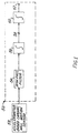
- a processing system 50 for deriving an improved hemodynamic indicator in accordance with the principles of the present invention is described.
- the processing system 50 is intended to receive input signals from an accelerometer-based cardiac wall motion sensor 52.
- the cardiac wall motion sensor 52 is mechanically couple to a region of a patient's cardiac wall (not shown) in a manner that allows the cardiac wall motion sensor 52 to respond to cardiac wall accelerations associated with cardiac contractile activity.
- Sensors that are particularly well-suited for use as the cardiac wall motion sensor 52 can have one of several types of implantable leads, including endocardial leads, myocardial active-fixation leads and epicardial patch electrodes, all of which may incorporate accelerometer-based cardiac wall motion sensors. These leads are not only useful for mechanically coupling the cardiac wall motion sensor 52 to the cardiac wall - they may also provide the electrodes (not shown) which are used to administer therapeutic electrical stimulation to cardiac tissue and to detect IEGMs, thereby reducing the number of leads that need to be implanted in the patient's body.
- the processing system 50 includes a high pass filter 54, which receives raw acceleration signals from the cardiac wall motion sensor 52.
- the high pass filter 54 selects signals associated with cardiac wall motion, and attenuates unwanted signals, such as those associated with body motion (in a manner described in greater detail below).
- the filtered acceleration signals are received by a first integrator circuit 56, which integrates the filtered acceleration signals over time to derive cardiac wall velocity signals.
- the cardiac wall velocity signals may be independently useful.
- velocity signals may be used as an indicator of cardiac contractility or sympathetic drive (i.e., an adrenaline-induced increase in heart action).
- velocity is the rate of change of displacement, it also provides a signal correlating to inflow and outflow of blood.
- the velocity signals are made available at a node 58, should this information be deemed valuable in connection with diagnosis or treatment for a particular patient.
- the velocity signals derived by the first integrator circuit 56 are received by a second integrator circuit 60, which integrates the velocity signals over time to derive cardiac wall displacement signals, which are made available at a node 62. Although it may be possible to make beneficial use of the cardiac wall displacement signals available at the node 62, it is preferable to further process the signals to derive the peak-to-peak displacement signals.
- Analog peak-to-peak detectors are well known in the art. However, in the preferred embodiment, peak-to-peak detection is achieved by a microprocessor.
- the cardiac wall displacement signals available at the node are directed to an analog-to-digital (A/D) converter via a multiplexer circuit.
- A/D analog-to-digital
- the digitised signal at the output of the A/D converter is then received by the microprocessor.
- a control program stored in a memory enables the microprocessor to determine a variety of information about the cardiac displacement signal, including (but not limited to) peak-to-peak information.
- Examples of other analog signals that are also known in the art to be multiplexed to the A/D converter for processing by the microprocessor include: atrial and ventricular IEGMs, battery voltage, battery current and/or battery impedance. If desired, the output of the accelerometer-based cardiac wall motion sensor 52, either before or after being processed through the high pass filter 54, could be directed to the microprocessor. Similarly, the velocity signals available at the node 58 could be directed to the microprocessor.
- the high pass filter 54, the first and second integrator circuitry 56 and 60 may be implemented using discrete analog components (see Fig. 2 below) or digital component, or some combination of the two.
- the processing system 50 is implemented using integrated circuitry on a hybrid (not shown) of an implantable cardiac stimulating device (described below in connection with FIG. 3 ).
- several or all of the processing steps described above may be accomplished by a microprocessor (shown in FIG. 3 ) in the implantable cardiac stimulating device.
- the block diagram of FIG. 1 represents a sequence of processing steps which may be performed by the microprocessor.
- FIG. 2 A preferred embodiment of the processing system 50 ( FIG. 1 ) which is implemented using analog circuitry that may be conveniently integrated into hybridized circuitry of an implantable cardiac stimulating device is shown in FIG. 2 .
- FIG. 2 For ease in comparing the components shown in FIG. 2 to the block diagram of FIG. 1 , like components are numbered using essentially the same reference numerals, except that they are increased by 100 in FIG. 2 .
- a processing system 150 includes a buffer 151 which receives the raw acceleration signals from the cardiac wall motion sensor 52 ( FIG. 1 ).
- the buffer 151 is used for impedance matching to downstream circuitry without introducing any phase shift.
- the buffer 151 may be implemented using a conventional operational amplifier 201 which has its inverting input coupled to its output.
- the buffer 151 may be coupled to an amplifier 153 to increase the strength of the input signals.
- the amplifier 153 may comprise an operational amplifier 203, a first bias resistor 205 (coupled between the output of the operational amplifier 201 and the inverting input of the operational amplifier 203) and a second bias resistor 207 (coupled between the inverting input and the output of the operational amplifier 203).
- the bias resistors 205 and 207 (which may both have resistances of about 25 K ⁇ ) are used to set the gain of the amplifier 153.
- the gain of the amplifier 153 may be changed by altering the ratio of the second bias resistor 207 to the first bias resistor 205, for example, by changing the value of the first bias resistor to about 5 K ⁇ would change the gain (i.e., the ratio of the resistor 207 to the resistor 205) from about 1 to about 5.
- the amplifier 153 is coupled to a high pass filter 154 which includes an operational amplifier 209, a capacitor 211 (coupled between the output of the operational amplifier 203 and the non-inverting input of the operational amplifier 209) and a resistor 213 (coupled between the non-inverting input of the operational amplifier 209 and ground) having a resistance of about 14 K ⁇ .
- Changing the value of the capacitor 211 will correspondingly change the frequency threshold of the high pass filter 154.
- the value of the capacitor 211 must be selected to filter signals in the range of about .1 Hz to about 2 Hz.
- resistor 213 is 14K ⁇
- the value of the capacitor 211 may be between about 47 ⁇ F and about 2 ⁇ F, respectively.
- the high pass filter 154 is coupled to a first integrator circuit 156 which includes an operational amplifier 217, a first resistor 215 (coupled between the output of the high pass filter 154 and the inverting input of the operational amplifier 217), a second resistor 219 (coupled between the non-inverting input of the operational amplifier 217 and ground), a third resistor 221 (coupled between the output and the inverting input of the operational amplifier 217), and a capacitor 223 connected in parallel with the resistor 221.
- the resistor 215 has a resistance of about 2.5K ⁇
- the resistors 219 and 221 may be about 2.2 K ⁇ and 25K ⁇ respectively.
- the capacitor 223 preferably has a capacitance of about 4.7 ⁇ F.
- the integrator 156 In addition to integrating the input signal, the integrator 156 also amplifies the signal in proportion to the ratio of the resistor 221 to the resistor 215 (which set the gain of the amplifier). The output of the first integrator circuit 156 may be connected to an output terminal 158, in order to provide signals representative of cardiac wall velocity.
- the second integrator circuit 160 (which is essentially identical to the first integrator circuit 156) includes an operational amplifier 227, three resistors 225, 229 and 231, and a capacitor 233.
- the resistors 225, 229 and 231, and the capacitor 233 have about the same values as, respectively, the resistors 215, 219 and 221, and the capacitor 223.
- the output of the second integrator circuit 160 may be coupled to an output terminal 162 to provide cardiac wall displacement signals.
- Each of the integrator circuits is biased so that a gain of 10 is applied to the input signal (because the integrator naturally reduces the high frequency component of the input signal).
- the signal has a gain of 100 (i.e., a gain of 10 applied by the first integrator 156, times the gain of 10 applied by the second integrator 160).
- a gain of 100 i.e., a gain of 10 applied by the first integrator 156, times the gain of 10 applied by the second integrator 160.
- the cardiac wall displacement signal at output terminal 162 may be used directly, it may be desirable to have some type of a detector circuitry, such as, a threshold detector, a comparator, a frequency counter, etc.
- a peak-to-peak detector is used to provide information corresponding the strength or vigor or the contraction.
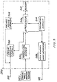
- FIG. 3 a block diagram is shown representing an implantable cardiac stimulating device 300 which provides therapeutic electrical stimulation to cardiac tissue in response to cardiac arrhythmias detected by using cardiac wall displacement as a hemodynamic indicator.
- the implantable cardiac stimulating device 300 as described below, is capable of providing bradycardia pacing therapy as well as higher energy therapies, such as cardioversion and defibrillation shocks.
- higher energy therapies such as cardioversion and defibrillation shocks.
- the principles of the present invention can be applied equally as well to simpler devices, such as dedicated bradycardia pacemakers, defibrillators or other implantable medical devices which may desire monitoring of hemodynamic performance, in view of the description below.
- the implantable cardiac stimulating device 300 delivers therapeutic electrical stimulation to a patient's heart (not shown) through leads 302 and 310 which are attached at one end to the implantable cardiac stimulating device 300, and at the other end (not shown) to a selected region of cardiac tissue.
- at least one pacing lead 302 is used to deliver pacing pulses generated by a pacing pulse generator 304 (which may be conventional) in accordance with instructions provided by a microprocessor 306.
- the pacing pulse generator 304 may be used to generate pacing pulses in any of the modes known for treating bradycardia and in addition, may be used to generate pacing pulses in a sequence known for interrupting tachycardia.
- the implantable cardiac stimulating device 300 also provides higher energy shock therapies to interrupt more severe cardiac arrhythmias.
- cardioversion shocks may be administered to revert ventricular tachycardia (VT), and defibrillation shocks may be administered to interrupt ventricular fibrillation (VF).
- VT revert ventricular tachycardia
- VF ventricular fibrillation
- These high energy shocks are generated by a high energy shock generator 308 (which may be conventional) under the control of the microprocessor 306.
- the high energy shocks are delivered to the patient's heart through at least one shocking lead 310.
- the pacing lead 302 and the shocking lead 310 are shown as physically separate leads, their respective electrodes may be provided by a single lead (not shown). Indeed, a great variety of lead configurations may be used in accordance with the principles of the present invention, so as to not diminish the flexibility that a medical practitioner normally has when selecting leads that meet the needs of a particular patient.
- the manner by which the implantable cardiac stimulating device 300 delivers pacing therapy and higher energy shock therapies is controlled by the microprocessor 306, to some extent, in accordance with parameters stored in a memory 312. Many of these parameters are known in the art (i.e., escape interval, refractory period, cardioversion shock energy, defibrillation shock energy, etc.), and they may be programmed by a medical practitioner using a programming unit (not shown) that communicates with the microprocessor 306 through a telemetry circuit 314.
- static parameters stored in the memory 312 do not provide the microprocessor 306 with all of the information necessary to control the manner by which therapies are administered by the implantable cardiac stimulating device 300. Rather, it is necessary for the microprocessor 306 to receive information pertaining to the patient's current cardiac condition in order to detect the onset of an arrhythmia and to select an appropriate form of electrical stimulation therapy in response to a detected arrhythmia.
- the microprocessor 306 receives information pertaining to the patient's cardiac condition from two sources -- an IEGM sensing circuit 316 and a processing system 350 (such as the processing system 50 described above in connection with FIG. 1 ).
- the IEGM sensing circuit 316 (which may be conventional), receives the patient's IEGM during periods when pacing pulses are not being administered through the pacing lead 302.
- the IEGM sensing circuit 316 uses the patient's IEGM to provide the microprocessor 306 with information pertaining to the patient's cardiac rate . This information may be used by the microprocessor 306 to cause the implantable cardiac stimulating device 300 to respond to the onset of an arrhythmia with an appropriate form of electrical stimulation therapy from either the pacing pulse generator 304 or the high energy shock generator 308.
- the implantable cardiac stimulating device 300 also includes the processing system 350, which provides cardiac wall displacement signals to the microprocessor 306.
- the cardiac wall displacement signals are derived from the raw acceleration signals provided by a cardiac wall motion sensor 352 (such as the cardiac wall motion sensor 52 described above in connection with FIG. 1 ).
- the cardiac wall displacement signals are a sensitive hemodynamic signal which is proportional to stroke volume and are not subject to interference from after-potentials, and unlike certain other hemodynamic indicators, they allow the microprocessor 306 to rapidly detect the onset of cardiac events which may be hemodynamically compromising.
- the microprocessor 306 may be programmed by a medical practitioner via the telemetry circuit 314 to operate in one of several modes. For example, the microprocessor 306 may be programmed to respond to either the processing system 350 or to the IEGM sensing circuit 316 exclusively. Alternatively, the microprocessor 306 may be programmed to respond primarily to either the processing system 350 or to the IEGM sensing circuit 316, and to use, as a secondary source of information, the source not designated as the primary source. For instance, the IEGM sensing circuit 316 may be used to confirm the onset of an episode of ventricular fibrillation first detected using the cardiac wall displacement signals provided by the processing system 350. Further, the extent to which a particular source of information is used may be programmed independently for each type of electrical stimulation therapy.
- the processing system 350 may be designated as the primary source of information for therapies provided by the high energy shock generator 308, whereas the IEGM sensing circuit may be the primary source of information for bradycardia pacing therapy provided by the pacing pulse generator 304.
- the cardiac wall displacement signals are derived using circuitry in the processing system 350 (such as the circuitry described above in connection with FIG. 2 ).
- therapeutic electrical stimulation may be administered equally as well by an implantable cardiac stimulating device which, instead of the processing system 350, includes a microprocessor that is programmed to derive cardiac wall displacement from raw acceleration signals provided by the cardiac wall motion sensor 352.
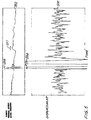
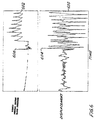
- FIGS. 4-7 cardiac wall displacement signals 400, 500, 600 and 700 derived in accordance with the principles of the present invention are described and compared to direct femoral artery blood pressure signals 402, 502, 602 and 702, respectively.
- the arterial blood pressure signals 402, 502, 602, 702 were measured by cannulating femoral artery with a fluid filled catheter connected to a pressure transducer, as is well known in the art.
- the cardiac wall displacement signals 400, 500, 600 and 700 are also shown as a function of time and synchronized to the blood pressure signals 402, 502, 602 and 702, respectively.
- direct blood pressure is an excellent hemodynamic signal, its use is limited to the setting of an operating room.
- the use of direct blood pressure as a reference signal serves to illustrate the correspondence of cardiac wall displacement to hemodynamic performance.
- the cardiac wall displacement signal 400 and the arterial blood pressure signal 402 are plotted simultaneously as a function of time for a subject in normal sinus rhythm.
- the cardiac wall displacement signal 400 exhibits a rhythmic pattern of excursions which closely tracks the pattern of excursions corresponding to the cardiac cycle of systole (the period of contraction, or high blood pressure) and diastole (the period of filling, or low blood pressure).
- Fig. 4 further illustrates the one-to-one correspondence with the arterial blood pressure signal 402, that is, each excursion of the cardiac wall displacement signal 400 slightly precedes a corresponding change in arterial blood pressure, as would be expected.
- Each excursion in the cardiac wall displacement signal 400 is related to a volume change and corresponds to a hemodynamically effective cardiac contraction.
- the subject's mechanical heart rate can be determined by counting the peaks in the cardiac wall displacement signal 400 over a predetermined period of time, in a manner similar to that which may be accomplished using the arterial blood pressure signal 402.
- the vigor of each cardiac contraction may be determined by measuring the peak-to-peak amplitude of each excursion in the cardiac wall displacement signal 400.
- the cardiac wall displacement signal 400 may be used to determine the subject's heart rate, it may also be used by the implantable cardiac stimulating device 300 ( FIG. 3 ) to administer bradycardia pacing therapy, and in particular, demand pacing therapy.
- Demand pacing may be accomplished using the cardiac wall displacement signal 400 as follows.
- the microprocessor 306 (FIG. 3) receives the cardiac wall displacement signal 400 and determines the subject's heart rate by counting over a predetermined period of time, the number of excursions that have an amplitude which exceeds a threshold amplitude. The predetermined period of time and threshold amplitude may be stored as parameters in the memory 312 ( FIG. 3 ).
- the microprocessor 306 determines that the subject's heart is beating at a physiologically acceptable rate, it inhibits the pacing pulse generator 304 ( FIG. 3 ) from generating pacing pulses. However, once the subject's heart rate falls below an acceptable rate, the microprocessor 306 ( FIG. 3 ) causes the pacing pulse generator 304 to generate pacing pulses which are delivered to the subject's heart through the pacing lead 302 ( FIG. 3 ). The microprocessor 306 ( FIG. 3 ) continues to monitor the subject's heart rate using the cardiac wall displacement signal 400 to determine when pacing pulses should be administered or inhibited.
- the cardiac wall displacement signal 500 and the arterial blood pressure signal 502 are plotted simultaneously as a function of time for a subject that first experienced fibrillation, and then tachycardia induced by an unsuccessful defibrillation shock.
- An excursion 504 in the cardiac wall displacement signal 500 represents an intense convulsion resulting from the defibrillation shock.
- arterial blood pressure signal 502 An inspection of the corresponding segments of the arterial blood pressure signal 502 reveals that arterial blood pressure dropped substantially continuously before the convulsion indicated by the excursion 506 due to fibrillation. However, arterial blood pressure increased somewhat after the convulsion (at point 507), indicating at least one effective contraction after the shock that although hemodynamic performance was compromised both before and after the convulsion, the subject's condition changed, albeit only slightly, after the defibrillation pulse was administered. More precisely, prior to the defibrillation shock, the arterial blood pressure signal 502 indicates that the subject experienced VF, and after the defibrillation shock, the subject experienced hemodynamically unstable VT. But perhaps most importantly, the cardiac wall displacement signal indicates, independently of the IEGMs, that the hemodynamic status before and after the shock is still compromised and that further and more aggressive therapy should be attempted immediately.
- the segments of the cardiac wall displacement signal 500 before and after the excursion 504 exhibit rapidly appearing, low amplitude excursions when compared to the cardiac wall displacement signal 400 of FIG. 4 .
- the cardiac wall displacement signal 500 reveals that the subject experienced hemodynamically compromising cardiac arrhythmias as effectively as the arterial blood pressure signal 502 reveals the same information.
- the excursions immediately after the shock generally have slightly higher amplitudes than the excursions in the earlier segment. Therefore, the cardiac wall displacement signal 500 not only reveals periods of hemodynamic compromise, it may also be used to detect particular types of hemodynamically compromising cardiac arrhythmias, even when the distinctions between arrhythmias are slight (i.e., VF prior to the excursion 504 and VT after the excursion 504).
- FIG. 6 shows the cardiac wall displacement signal 600 and the arterial blood pressure signal 602 from a subject that received a successful defibrillation shock.
- the convulsion and corresponding rise in pressure are apparent from, respectively, an excursion 604 in the cardiac wall displacement signal 600 and an excursion 606 in the arterial blood pressure signal 602.
- the characteristic drop in blood pressure associated with VF is evident from the segment of the arterial blood pressure signal 602 preceding the excursion 606. This hemodynamically compromising event is also apparent from the low amplitude, rapidly fluctuating segment of the cardiac wall displacement signal 600 preceding the excursion 604.
- the subject Following the defibrillation shock, the subject enters post-shock sinus rhythm, during which the subject recovers from an oxygen deficit.
- the arterial blood pressure signal 602 shows a rapid rise in blood pressure, followed by a gradual reduction in blood pressure as the subject recovers.
- Post-shock sinus rhythm is also apparent from the cardiac wall displacement signal 600, which shows large amplitude excursions appearing immediately after the excursion 604 at an extremely rapid rate. The rate gradually decreases as the subject recovers from the oxygen deficit. Therefore, the cardiac wall displacement signal indicates, independently of the IEGM, that therapy was successful and that no further therapy is needed. Both indicators are valuable in the operation of an implantable cardiovertor/defibrillator device.
- the microprocessor 306 When the microprocessor 306 ( FIG. 3 ) receives an indication that the subject is experiencing one of the arrhythmias shown in FIGS. 5 and 6 (i.e., VT in the cardiac wall displacement signal 500 of FIG. 5 , and VF in either of the cardiac wall displacement signals 500 and 600 of FIGS. 5 and 6 , respectively), it may initiate delivery of electrical stimulation therapy to interrupt the arrhythmia. For example, if hemodynamically stable VT is indicated, the microprocessor 306 ( FIG. 3 ) may cause the pacing pulse generator 304 ( FIG. 3 ) to generate pacing pulses in a sequence that is known for interrupting VT. Alternatively, the microprocessor 306 ( FIG. 3 ) may cause the high energy shock generator 308 ( FIG. 3 ) to administer a cardioversion shock if the VT is determined to be hemodynamically unstable. If VF is indicated, the microprocessor 306 ( FIG. 3 ) may cause the high energy shock generator 308 to administer a defibri
- FIG. 7 is presented as another illustration of the utility of cardiac wall displacement as a hemodynamic indicator.
- both the cardiac wall displacement signal 700 and the arterial blood pressure signal 702 reveal an ectopic heartbeat (e.g., a premature ventricular beat (PVC)) occurring during normal sinus rhythm.
- the ectopic heartbeat is apparent from a low amplitude excursion 704 appearing suddenly among large amplitude excursions representative of hemodynamically effective cardiac contractions in the cardiac wall displacement signal 700.
- a drop in blood pressure is apparent from a segment 706 of the arterial blood pressure signal 702 corresponding to the excursion 704 in the cardiac wall displacement signal 700.
- the cardiac wall displacement signal 700 provides enough resolution to detect even transient changes in hemodynamic performance.
- the reporting of ectopic beats is useful information for patients implanted with cardiac devices. For example, reporting the number of ectopic beats per hour is a useful indicator for patients undergoing serial drug testing for the suppression of such events.
Landscapes
- Health & Medical Sciences (AREA)
- Cardiology (AREA)
- Heart & Thoracic Surgery (AREA)
- Life Sciences & Earth Sciences (AREA)
- General Health & Medical Sciences (AREA)
- Engineering & Computer Science (AREA)
- Biomedical Technology (AREA)
- Nuclear Medicine, Radiotherapy & Molecular Imaging (AREA)
- Radiology & Medical Imaging (AREA)
- Animal Behavior & Ethology (AREA)
- Public Health (AREA)
- Veterinary Medicine (AREA)
- Biophysics (AREA)
- Physiology (AREA)
- Hematology (AREA)
- Electrotherapy Devices (AREA)
- Measurement And Recording Of Electrical Phenomena And Electrical Characteristics Of The Living Body (AREA)
Claims (14)
- Dispositif de stimulation cardiaque implantable pour fournir une stimulation électrique thérapeutique pour traiter des arythmies cardiaques, le dispositif de stimulation comprenant un circuit qui génère une stimulation électrique (304) pour générer la stimulation électrique thérapeutique, dans lequel le dispositif de stimulation présente :un détecteur de mouvement de la paroi cardiaque (52) y associé, disposé pour fournir un signal d'accélération de la paroi cardiaque et caractérisé par :un circuit de traitement (50) disposé pour dériver un signal de déplacement de la paroi cardiaque à partir du signal d'accélération de la paroi cardiaque et pour dériver un signal d'arythmie reflétant le début d'arythmies cardiaques compromettantes d'un point de vue hémodynamique à partir du signal de déplacement de la paroi cardiaque ; etun circuit de commande (50) pour réguler le circuit qui génère la stimulation électrique selon le signal d'arythmie.
- Dispositif de stimulation selon la revendication 1, caractérisé en ce que le signal d'arythmie correspond à un signal de contractilité, de tonus sympathique, de débit sanguin, de déplacement de fluide ou de débit systolique.
- Dispositif de stimulation selon la revendication 1 ou la revendication 2, caractérisé en ce que le circuit de traitement (50) comprend en outre un circuit pour dériver un signal représentatif de la vitesse de la paroi cardiaque à partir du signal d'accélération de la paroi cardiaque, de préférence un circuit pour intégrer le signal d'accélération de la paroi cardiaque dans le temps.
- Dispositif de stimulation selon la revendication 1 ou la revendication 2, caractérisé en ce que le circuit de traitement (50) comprend un circuit pour intégrer deux fois le signal d'accélération de la paroi cardiaque dans le temps pour dériver le signal de déplacement de la paroi cardiaque.
- Dispositif de stimulation selon la revendication 4, caractérisé en ce que le circuit de traitement (50) comprend en outre un circuit pour dériver un signal de déplacement de la paroi cardiaque de pic en pic à partir du signal représentant le déplacement de la paroi cardiaque.
- Dispositif de stimulation selon l'une quelconque des revendications précédentes, caractérisé en ce que le circuit de traitement (50) et le circuit de commande (50) comprennent un microprocesseur.
- Dispositif de stimulation selon l'une quelconque des revendications précédentes, caractérisé en ce que le circuit de commande (50) évalue le signal d'arythmie pour détecter les arythmies cardiaques et fait que le circuit qui génère la stimulation électrique (304) génère la stimulation électrique thérapeutique quand l'arythmie cardiaque est détectée.
- Dispositif de stimulation selon la revendication 7, caractérisé en ce que le circuit qui génère la stimulation électrique (304) comprend un générateur d'impulsions d'électrosystolie pour générer des impulsions d'électrosystolie quand le circuit de commande (50) détecte une indication de bradycardie dans le signal d'arythmie et pour générer des impulsions d'électrosystolie en une séquence pour interrompre la tachycardie quand le circuit de commande (50) détecte une indication de tachycardie hémodynamiquement stable dans le signal hémodynamique.
- Dispositif de stimulation selon la revendication 7, caractérisé en ce que le circuit qui génère la stimulation électrique (304) comprend un générateur de chocs à haut énergie (308) pour générer un choc pour la cardioversion quand le circuit de commande (50) détecte une indication de tachycardie hémodynamiquement instable dans le signal d'arythmie ou pour générer un choc de défibrillation quand le circuit de commande (50) détecte une indication de fibrillation dans le signal d'arythmie.
- Dispositif de stimulation selon l'une quelconque des revendications précédentes, caractérisé par :un moyen (316) pour détecter des signaux de dépolarisation cardiaque ;un moyen (350) pour détecter une diminution du signal d'arythmie ;un moyen (350) pour définir un signal de dépolarisation cardiaque comme une extrasystole chaque fois qu'une diminution correspondante est détectée dans le signal d'arythmie ; et un moyen pour stocker les informations relatives aux extrasystoles détectées.
- Dispositif de stimulation selon l'une quelconque des revendications précédentes, caractérisé en outre par un circuit d'entrée (350) pour recevoir le signal d'accélération de la paroi cardiaque, le circuit de traitement étant couplé au circuit d'entrée.
- Dispositif de stimulation selon la revendication 11, caractérisé en ce que le circuit d'entrée (350) comprend un filtre passe-haut qui sélectionne les signaux associés au mouvement de la paroi cardiaque et rejette les signaux associés au mouvement du corps.
- Dispositif de stimulation selon l'une quelconque des revendications précédentes, caractérisé en ce que :le détecteur de mouvement de la paroi cardiaque (52) fournit un premier signal d'arythmie ;un circuit d'entrée (350) reçoit le premier signal d'arythmie ; etle circuit de traitement, couplé au circuit d'entrée, dérive un deuxième signal d'arythmie.
- Dispositif de stimulation selon la revendication 13, caractérisé en ce que le premier signal d'arythmie est un signal d'accélération de la paroi cardiaque ; et le deuxième signal d'arythmie correspond à un signal qui représente un signal de contractilité, de tonus sympathique, de débit sanguin, de déplacement de fluide ou de débit systolique.
Applications Claiming Priority (3)
| Application Number | Priority Date | Filing Date | Title |
|---|---|---|---|
| US08/154,800 US5480412A (en) | 1993-11-16 | 1993-11-16 | System and method for deriving hemodynamic signals from a cardiac wall motion sensor |
| US154800 | 1993-11-16 | ||
| PCT/US1994/013134 WO1995013741A1 (fr) | 1993-11-16 | 1994-11-14 | Signaux hemodynamiques derives d'un detecteur de mouvement de la paroi cardiaque |
Publications (3)
| Publication Number | Publication Date |
|---|---|
| EP0687159A1 EP0687159A1 (fr) | 1995-12-20 |
| EP0687159A4 EP0687159A4 (fr) | 1996-02-07 |
| EP0687159B1 true EP0687159B1 (fr) | 2002-07-24 |
Family
ID=22552842
Family Applications (1)
| Application Number | Title | Priority Date | Filing Date |
|---|---|---|---|
| EP95901909A Expired - Lifetime EP0687159B1 (fr) | 1993-11-16 | 1994-11-14 | Signaux hemodynamiques derives d'un detecteur de mouvement de la paroi cardiaque |
Country Status (6)
| Country | Link |
|---|---|
| US (1) | US5480412A (fr) |
| EP (1) | EP0687159B1 (fr) |
| JP (1) | JPH08510947A (fr) |
| AU (1) | AU1097495A (fr) |
| DE (1) | DE69431044T2 (fr) |
| WO (1) | WO1995013741A1 (fr) |
Families Citing this family (80)
| Publication number | Priority date | Publication date | Assignee | Title |
|---|---|---|---|---|
| US6077236A (en) * | 1994-06-07 | 2000-06-20 | Cunningham; David | Apparatus for monitoring cardiac contractility |
| US5836987A (en) * | 1995-11-15 | 1998-11-17 | Cardiac Pacemakers, Inc. | Apparatus and method for optimizing cardiac performance by determining the optimal timing interval from an accelerometer signal |
| US5913826A (en) * | 1996-06-12 | 1999-06-22 | K-One Technologies | Wideband external pulse cardiac monitor |
| US7097618B1 (en) * | 2003-03-12 | 2006-08-29 | Transoma Medical, Inc. | Devices and methods for detecting and treating inadequate tissue perfusion |
| US5991661A (en) * | 1997-10-17 | 1999-11-23 | Pacesetter, Inc. | System and method for measuring cardiac activity |
| US6026324A (en) * | 1998-10-13 | 2000-02-15 | Cardiac Pacemakers, Inc. | Extraction of hemodynamic pulse pressure from fluid and myocardial accelerations |
| US6552531B1 (en) * | 1998-10-14 | 2003-04-22 | Continental Teves Ag & Co., Ohg | Method and circuit for processing signals for a motion sensor |
| US6128526A (en) * | 1999-03-29 | 2000-10-03 | Medtronic, Inc. | Method for ischemia detection and apparatus for using same |
| US6115630A (en) * | 1999-03-29 | 2000-09-05 | Medtronic, Inc. | Determination of orientation of electrocardiogram signal in implantable medical devices |
| US6324421B1 (en) | 1999-03-29 | 2001-11-27 | Medtronic, Inc. | Axis shift analysis of electrocardiogram signal parameters especially applicable for multivector analysis by implantable medical devices, and use of same |
| US6115628A (en) | 1999-03-29 | 2000-09-05 | Medtronic, Inc. | Method and apparatus for filtering electrocardiogram (ECG) signals to remove bad cycle information and for use of physiologic signals determined from said filtered ECG signals |
| US6179865B1 (en) * | 1999-04-01 | 2001-01-30 | Cardiac Pacemakers, Inc. | Cross chamber interval correlation |
| US7203535B1 (en) | 1999-04-01 | 2007-04-10 | Cardiac Pacemakers, Inc. | System and method for classifying tachycardia arrhythmias having 1:1 atrial-to-ventricular rhythms |
| US6263241B1 (en) | 1999-04-30 | 2001-07-17 | Intermedics, Inc. | Method and apparatus for treatment of cardiac electromechanical dissociation |
| US6298267B1 (en) | 1999-04-30 | 2001-10-02 | Intermedics Inc. | Method and apparatus for treatment of cardiac electromechanical dissociation |
| EP1142608A2 (fr) | 2000-04-05 | 2001-10-10 | Pacesetter, Inc. | Procédé et système de prévention d'une syncope vaso-vagale récurrente utilisant la stimulation cardiaque |
| US6522914B1 (en) * | 2000-07-14 | 2003-02-18 | Cardiac Pacemakers, Inc. | Method and apparatuses for monitoring hemodynamic activities using an intracardiac impedance-derived parameter |
| US6684100B1 (en) * | 2000-10-31 | 2004-01-27 | Cardiac Pacemakers, Inc. | Curvature based method for selecting features from an electrophysiologic signals for purpose of complex identification and classification |
| US7069070B2 (en) * | 2003-05-12 | 2006-06-27 | Cardiac Pacemakers, Inc. | Statistical method for assessing autonomic balance |
| US7215992B2 (en) * | 2001-10-31 | 2007-05-08 | Cardiac Pacemakers, Inc. | Method for ischemia detection by implantable cardiac device |
| US7181268B2 (en) * | 2001-12-03 | 2007-02-20 | Medtronic, Inc. | Ischemia detection |
| NO20016385L (no) * | 2001-12-27 | 2003-06-30 | Medinnova Sf | System for å overvåke pulsendringer, fortrinnsvis en hjertemuskel |
| US6922587B2 (en) * | 2002-06-26 | 2005-07-26 | Pacesetter, Inc. | System and method for tracking progression of left ventricular dysfunction using implantable cardiac stimulation device |
| US7092757B2 (en) | 2002-07-12 | 2006-08-15 | Cardiac Pacemakers, Inc. | Minute ventilation sensor with dynamically adjusted excitation current |
| US6978184B1 (en) * | 2002-07-29 | 2005-12-20 | Marcus Frank I | Optimization method for cardiac resynchronization therapy |
| US7101339B2 (en) * | 2002-12-13 | 2006-09-05 | Cardiac Pacemakers, Inc. | Respiration signal measurement apparatus, systems, and methods |
| US8050764B2 (en) | 2003-10-29 | 2011-11-01 | Cardiac Pacemakers, Inc. | Cross-checking of transthoracic impedance and acceleration signals |
| US7272442B2 (en) | 2002-12-30 | 2007-09-18 | Cardiac Pacemakers, Inc. | Automatically configurable minute ventilation sensor |
| US7529583B1 (en) * | 2003-01-15 | 2009-05-05 | Transoma Medical, Inc. | Therapeutic device and method using feedback from implantable pressure sensor |
| US6871088B2 (en) * | 2003-03-20 | 2005-03-22 | Medtronic, Inc. | Method and apparatus for optimizing cardiac resynchronization therapy |
| US7130681B2 (en) | 2003-05-09 | 2006-10-31 | Medtronic, Inc. | Use of accelerometer signal to augment ventricular arrhythmia detection |
| US7792571B2 (en) * | 2003-06-27 | 2010-09-07 | Cardiac Pacemakers, Inc. | Tachyarrhythmia detection and discrimination based on curvature parameters |
| US7500955B2 (en) | 2003-06-27 | 2009-03-10 | Cardiac Pacemaker, Inc. | Signal compression based on curvature parameters |
| US7003348B1 (en) * | 2003-07-01 | 2006-02-21 | Pacesetter, Inc. | Monitoring cardiac geometry for diagnostics and therapy |
| US7200440B2 (en) | 2003-07-02 | 2007-04-03 | Cardiac Pacemakers, Inc. | Cardiac cycle synchronized sampling of impedance signal |
| US7392084B2 (en) | 2003-09-23 | 2008-06-24 | Cardiac Pacemakers, Inc. | Demand-based cardiac function therapy |
| US7572226B2 (en) | 2003-10-28 | 2009-08-11 | Cardiac Pacemakers, Inc. | System and method for monitoring autonomic balance and physical activity |
| US20070197859A1 (en) * | 2003-11-07 | 2007-08-23 | Paracor Medical, Inc. | Cardiac harness having diagnostic sensors and method of use |
| US7515956B2 (en) * | 2004-05-12 | 2009-04-07 | Cardiac Pacemakers, Inc. | Template based AV/VA interval comparison for the discrimination of cardiac arrhythmias |
| WO2006025770A1 (fr) * | 2004-08-31 | 2006-03-09 | St. Jude Medical Ab | Appareil et methode de detection de l'insuffisance cardiaque diastolique |
| US9457184B2 (en) * | 2005-04-06 | 2016-10-04 | Berlin Heals Holding Ag | Electromedical implantable or extracorporeally applicable device for the treatment or monitoring of organs, and method for therapeutic organ treatment |
| US20160361559A1 (en) | 2007-10-12 | 2016-12-15 | Berlin Heals Holding Ag | Electromedical implantable or extracorporeally applicable device for the treatment or monitoring of organs, and method for therapeutic organ treatment |
| US20060235289A1 (en) * | 2005-04-19 | 2006-10-19 | Willem Wesselink | Pacemaker lead with motion sensor |
| GB2428977A (en) * | 2005-08-08 | 2007-02-14 | Ai Semi Ltd | Pacemaker or defibrillator using combined electrogram and haemodynamic data |
| WO2007103362A2 (fr) * | 2006-03-08 | 2007-09-13 | Ascension Technology Corporation | Localisation de fils de defibrillateur a synchronisation automatique implantable et de dispositifs de traitement par resynchronisation cardiaque |
| US7643879B2 (en) | 2006-08-24 | 2010-01-05 | Cardiac Pacemakers, Inc. | Integrated cardiac rhythm management system with heart valve |
| WO2009075949A1 (fr) * | 2007-12-11 | 2009-06-18 | Cardiac Pacemakers, Inc. | Capteur hémodynamique pour veine coronaire |
| EP2196238B1 (fr) * | 2008-12-12 | 2011-05-25 | Ela Medical | Dispositif médical actif du type prothèse cardiaque implantable, comprenant des moyens de stimulation auriculaire antitachycardique et de stimulation ventriculaire antibradycardique |
| EP2435131A1 (fr) * | 2009-05-26 | 2012-04-04 | Cardiac Pacemakers, Inc. | Système et procédé d'identification de rythme et de discrimination de thérapie à l'aide d'informations d'état hémodynamique |
| US8417336B2 (en) * | 2009-06-01 | 2013-04-09 | Cardiac Pacemakers, Inc. | System and method for pacing rate control utilizing patient hemodynamic status information |
| JP2012528607A (ja) * | 2009-06-01 | 2012-11-15 | カーディアック ペースメイカーズ, インコーポレイテッド | 患者の血行動態に基づく代償不全の検出および処置のためのシステムおよび方法 |
| US8532769B2 (en) * | 2009-10-30 | 2013-09-10 | Medtronic, Inc. | Heart rate variability distinction |
| JP5230877B2 (ja) * | 2010-02-09 | 2013-07-10 | カーディアック ペースメイカーズ, インコーポレイテッド | 心房興奮の変化を用いた不整脈中の血行動態の安定性の検出 |
| US9241640B2 (en) | 2010-07-28 | 2016-01-26 | Medtronic, Inc. | Measurement of cardiac cycle length and pressure metrics from pulmonary arterial pressure |
| US20120095521A1 (en) * | 2010-10-19 | 2012-04-19 | Medtronic, Inc. | Detection of heart rhythm using an accelerometer |
| US9314205B2 (en) | 2011-04-28 | 2016-04-19 | Medtronic, Inc. | Measurement of cardiac cycle length and pressure metrics from pulmonary arterial pressure |
| US8827913B2 (en) | 2011-05-03 | 2014-09-09 | Medtronic, Inc. | Verification of pressure metrics |
| US8812102B2 (en) | 2011-05-23 | 2014-08-19 | Cardiac Pacemakers, Inc. | Sensor response delay for hemodynamic stability detection during arrhythmia |
| JP2014530714A (ja) * | 2011-10-20 | 2014-11-20 | ボード・オブ・リージエンツ,ザ・ユニバーシテイ・オブ・テキサス・システム | 血行動態を用いて患者の心臓を治療する方法及び装置 |
| US8996101B2 (en) * | 2012-03-12 | 2015-03-31 | Medtronic, Inc. | Heart sound sensing to reduce inappropriate tachyarrhythmia therapy |
| JP6178424B2 (ja) | 2012-11-14 | 2017-08-09 | ヴェクトリアス メディカル テクノロジーズ リミテッド | 埋め込み型静電容量ベース圧力変換器のためのドリフト補償 |
| US10205488B2 (en) | 2013-04-18 | 2019-02-12 | Vectorious Medical Technologies Ltd. | Low-power high-accuracy clock harvesting in inductive coupling systems |
| WO2014170771A1 (fr) | 2013-04-18 | 2014-10-23 | Vectorious Medical Technologies Ltd. | Implant sensoriel alimenté à distance |
| WO2016178197A1 (fr) | 2015-05-07 | 2016-11-10 | Vectorious Medical Technologies Ltd | Déploiement et fixation d'un implant à travers une paroi d'organe |
| DE102015109037A1 (de) | 2015-06-09 | 2016-12-15 | Biotronik Se & Co. Kg | Ratenadaptiver intra- oder epicardialer Herzstimulator und Aktivitätssensor |
| WO2017040115A1 (fr) | 2015-08-28 | 2017-03-09 | Cardiac Pacemakers, Inc. | Système de détection de tamponnade |
| US10123742B2 (en) * | 2015-12-02 | 2018-11-13 | Cardiac Pacemakers, Inc. | Methods and devices combining multiple cardiac rate measurements with interval correction and arrhythmia decision bypass |
| EP3398237B1 (fr) | 2015-12-30 | 2020-12-02 | Vectorious Medical Technologies Ltd. | Implant de capteur de pression efficace en énergie |
| US10532212B2 (en) | 2016-09-29 | 2020-01-14 | Medtronic, Inc. | Atrial tracking in an intracardiac ventricular pacemaker |
| US10449366B2 (en) | 2016-09-29 | 2019-10-22 | Medtronic, Inc. | Atrial tracking in an intracardiac ventricular pacemaker |
| US10286214B2 (en) | 2016-11-03 | 2019-05-14 | Medtronic, Inc. | Atrial tracking in an intracardiac ventricular pacemaker |
| US10207116B2 (en) | 2016-12-01 | 2019-02-19 | Medtronic, Inc. | Pacing mode switching in a ventricular pacemaker |
| US10864377B2 (en) | 2016-12-01 | 2020-12-15 | Medtronic, Inc. | Pacing mode switching in a ventricular pacemaker |
| US10328270B2 (en) | 2016-12-13 | 2019-06-25 | Medtronic, Inc. | Input switching in a ventricular intracardiac pacemaker |
| US11185701B2 (en) | 2018-04-09 | 2021-11-30 | Medtronic, Inc. | Pacing mode switching and rate response limit in a ventricular pacemaker |
| US11123005B2 (en) | 2018-11-12 | 2021-09-21 | Medtronic, Inc | Method and apparatus for atrial tachyarrhythmia detection |
| US11850433B2 (en) | 2018-12-06 | 2023-12-26 | Medtronic, Inc. | Method and apparatus for establishing parameters for cardiac event detection |
| US11819697B2 (en) | 2020-01-30 | 2023-11-21 | Medtronic, Inc. | Method and apparatus for adjusting control parameters for cardiac event sensing |
| US12440681B2 (en) | 2021-06-22 | 2025-10-14 | Medtronic, Inc. | Method and apparatus for establishing parameters for cardiac event detection |
| US12472364B2 (en) | 2021-11-01 | 2025-11-18 | Medtronic, Inc. | Post-ventricular atrial blanking in a cardiac device |
Family Cites Families (18)
| Publication number | Priority date | Publication date | Assignee | Title |
|---|---|---|---|---|
| US3815611A (en) * | 1971-11-26 | 1974-06-11 | Medtronic Inc | Muscle stimulation and/or contraction detection device |
| US4140132A (en) * | 1978-03-23 | 1979-02-20 | Dahl Joseph D | Variable rate timer for a cardiac pacemaker |
| EP0052162A1 (fr) * | 1980-11-19 | 1982-05-26 | Erich Charwat | Machine à piston rotatif fonctionnant avec des gaz expansibles |
| US4428378A (en) * | 1981-11-19 | 1984-01-31 | Medtronic, Inc. | Rate adaptive pacer |
| US4485813A (en) * | 1981-11-19 | 1984-12-04 | Medtronic, Inc. | Implantable dynamic pressure transducer system |
| US4802481A (en) * | 1984-07-19 | 1989-02-07 | Cordis Leads, Inc. | Apparatus for controlling pacing of a heart in response to changes in stroke volume |
| US4708143A (en) * | 1984-07-19 | 1987-11-24 | Cordis Leads Inc. | Method for controlling pacing of a heart in response to changes in stroke volume |
| DE3631155A1 (de) * | 1986-09-12 | 1988-03-24 | Alt Eckhard | Frequenzvariabler herzschrittmacher mit belastungsadaequatem frequenzverhalten |
| US5156148A (en) * | 1987-10-06 | 1992-10-20 | Leonard Bloom | System for treating a malfunctioning heart |
| US4967748A (en) * | 1987-10-06 | 1990-11-06 | Leonard Bloom | O2 level responsive system for and method of treating a malfunctioning heart |
| US4774950A (en) * | 1987-10-06 | 1988-10-04 | Leonard Bloom | Hemodynamically responsive system for and method of treating a malfunctioning heart |
| US5040534A (en) * | 1989-01-25 | 1991-08-20 | Siemens-Pacesetter, Inc. | Microprocessor controlled rate-responsive pacemaker having automatic rate response threshold adjustment |
| US5040535A (en) * | 1989-01-25 | 1991-08-20 | Siemens-Pacesetter, Inc. | Average amplitude controlled rate-responsive pacemaker having automatically adjustable control parameters |
| US5109842A (en) * | 1990-09-24 | 1992-05-05 | Siemens Pacesetter, Inc. | Implantable tachyarrhythmia control system having a patch electrode with an integrated cardiac activity system |
| US5184614A (en) * | 1990-10-19 | 1993-02-09 | Telectronics Pacing Systems, Inc. | Implantable haemodynamically responsive cardioverting/defibrillating pacemaker |
| US5156147A (en) * | 1991-02-05 | 1992-10-20 | Cardiac Pacemakers, Inc. | Variable rate pacemaker having upper rate limit governor based on hemodynamic performance |
| IT1245814B (it) * | 1991-05-21 | 1994-10-18 | Sorin Biomedica Spa | Dispositivo cardiostimolatore del tipo rate responsive |
| IT1256900B (it) * | 1992-07-27 | 1995-12-27 | Franco Vallana | Procedimento e dispositivo per rilevare la funzionalita` cardiaca. |
-
1993
- 1993-11-16 US US08/154,800 patent/US5480412A/en not_active Expired - Lifetime
-
1994
- 1994-11-14 JP JP7514549A patent/JPH08510947A/ja active Pending
- 1994-11-14 AU AU10974/95A patent/AU1097495A/en not_active Abandoned
- 1994-11-14 WO PCT/US1994/013134 patent/WO1995013741A1/fr not_active Ceased
- 1994-11-14 DE DE69431044T patent/DE69431044T2/de not_active Expired - Fee Related
- 1994-11-14 EP EP95901909A patent/EP0687159B1/fr not_active Expired - Lifetime
Also Published As
| Publication number | Publication date |
|---|---|
| DE69431044T2 (de) | 2003-04-03 |
| EP0687159A4 (fr) | 1996-02-07 |
| US5480412A (en) | 1996-01-02 |
| DE69431044D1 (de) | 2002-08-29 |
| WO1995013741A1 (fr) | 1995-05-26 |
| JPH08510947A (ja) | 1996-11-19 |
| AU1097495A (en) | 1995-06-06 |
| EP0687159A1 (fr) | 1995-12-20 |
Similar Documents
| Publication | Publication Date | Title |
|---|---|---|
| US5480412A (en) | System and method for deriving hemodynamic signals from a cardiac wall motion sensor | |
| US6009349A (en) | System and method for deriving hemodynamic signals from a cardiac wall motion sensor | |
| US7130681B2 (en) | Use of accelerometer signal to augment ventricular arrhythmia detection | |
| US8295927B2 (en) | Closed loop impedance-based cardiac resynchronization therapy systems, devices, and methods | |
| EP1572296B1 (fr) | Detection d'ischemie basee sur le temps de conduction cardiaque | |
| CN106456023B (zh) | 用于使用心音来检测房性快速性心律失常的方法和装置 | |
| US20110257547A1 (en) | Method and apparatus for controlling cardiac resynchronization therapy using cardiac impedance | |
| JP5178815B2 (ja) | 同期不全の閉ループ再同期治療 | |
| EP2320999A1 (fr) | Détection de détermination d'intégrité sur la base de la pression cardio-vasculaire | |
| US20090234401A1 (en) | Deactivation of intermittent pacing therapy | |
| US7654964B1 (en) | System and method for detecting arterial blood pressure based on aortic electrical resistance using an implantable medical device | |
| EP1663388B1 (fr) | Stimulation par excitation neuronale electrique | |
| US8825156B2 (en) | System and method for decompensation detection and treatment based on patient hemodynamics | |
| EP1617902B1 (fr) | Controle d'un complexe qrs en vue d'identifier une dysfonction du ventricule gauche | |
| US8103344B2 (en) | Method, device, implantable stimulator and dual chamber cardiac therapy system | |
| WO2003043692A2 (fr) | Systeme de stimulation de frequence asservie avec capteur qt fonde sur des donnees qt intrinseques | |
| EP1747752A1 (fr) | Caractérisation de la condition du patient en évaluant les propriétés électriques et mécaniques du coeur | |
| GB2428977A (en) | Pacemaker or defibrillator using combined electrogram and haemodynamic data |
Legal Events
| Date | Code | Title | Description |
|---|---|---|---|
| PUAI | Public reference made under article 153(3) epc to a published international application that has entered the european phase |
Free format text: ORIGINAL CODE: 0009012 |
|
| 17P | Request for examination filed |
Effective date: 19950831 |
|
| AK | Designated contracting states |
Kind code of ref document: A1 Designated state(s): DE ES FR GB IT NL |
|
| A4 | Supplementary search report drawn up and despatched |
Effective date: 19951221 |
|
| AK | Designated contracting states |
Kind code of ref document: A4 Designated state(s): DE ES FR GB IT NL |
|
| RIN1 | Information on inventor provided before grant (corrected) |
Inventor name: MOBERG, SHELDON B. Inventor name: MCCLURE, KELLY H. Inventor name: MOUCHAWAR, GABRIEL |
|
| 17Q | First examination report despatched |
Effective date: 20000925 |
|
| GRAG | Despatch of communication of intention to grant |
Free format text: ORIGINAL CODE: EPIDOS AGRA |
|
| GRAG | Despatch of communication of intention to grant |
Free format text: ORIGINAL CODE: EPIDOS AGRA |
|
| GRAH | Despatch of communication of intention to grant a patent |
Free format text: ORIGINAL CODE: EPIDOS IGRA |
|
| GRAH | Despatch of communication of intention to grant a patent |
Free format text: ORIGINAL CODE: EPIDOS IGRA |
|
| GRAA | (expected) grant |
Free format text: ORIGINAL CODE: 0009210 |
|
| AK | Designated contracting states |
Kind code of ref document: B1 Designated state(s): DE ES FR GB IT NL |
|
| PG25 | Lapsed in a contracting state [announced via postgrant information from national office to epo] |
Ref country code: NL Free format text: LAPSE BECAUSE OF FAILURE TO SUBMIT A TRANSLATION OF THE DESCRIPTION OR TO PAY THE FEE WITHIN THE PRESCRIBED TIME-LIMIT Effective date: 20020724 |
|
| REG | Reference to a national code |
Ref country code: GB Ref legal event code: FG4D |
|
| REF | Corresponds to: |
Ref document number: 69431044 Country of ref document: DE Date of ref document: 20020829 |
|
| PG25 | Lapsed in a contracting state [announced via postgrant information from national office to epo] |
Ref country code: GB Free format text: LAPSE BECAUSE OF NON-PAYMENT OF DUE FEES Effective date: 20021114 |
|
| ET | Fr: translation filed | ||
| NLV1 | Nl: lapsed or annulled due to failure to fulfill the requirements of art. 29p and 29m of the patents act | ||
| PG25 | Lapsed in a contracting state [announced via postgrant information from national office to epo] |
Ref country code: ES Free format text: LAPSE BECAUSE OF FAILURE TO SUBMIT A TRANSLATION OF THE DESCRIPTION OR TO PAY THE FEE WITHIN THE PRESCRIBED TIME-LIMIT Effective date: 20030130 |
|
| PLBE | No opposition filed within time limit |
Free format text: ORIGINAL CODE: 0009261 |
|
| STAA | Information on the status of an ep patent application or granted ep patent |
Free format text: STATUS: NO OPPOSITION FILED WITHIN TIME LIMIT |
|
| GBPC | Gb: european patent ceased through non-payment of renewal fee | ||
| 26N | No opposition filed |
Effective date: 20030425 |
|
| PGFP | Annual fee paid to national office [announced via postgrant information from national office to epo] |
Ref country code: FR Payment date: 20081117 Year of fee payment: 15 |
|
| PGFP | Annual fee paid to national office [announced via postgrant information from national office to epo] |
Ref country code: DE Payment date: 20081223 Year of fee payment: 15 |
|
| PGFP | Annual fee paid to national office [announced via postgrant information from national office to epo] |
Ref country code: IT Payment date: 20091128 Year of fee payment: 16 |
|
| REG | Reference to a national code |
Ref country code: FR Ref legal event code: ST Effective date: 20100730 |
|
| PG25 | Lapsed in a contracting state [announced via postgrant information from national office to epo] |
Ref country code: FR Free format text: LAPSE BECAUSE OF NON-PAYMENT OF DUE FEES Effective date: 20091130 |
|
| PG25 | Lapsed in a contracting state [announced via postgrant information from national office to epo] |
Ref country code: DE Free format text: LAPSE BECAUSE OF NON-PAYMENT OF DUE FEES Effective date: 20100601 |
|
| PG25 | Lapsed in a contracting state [announced via postgrant information from national office to epo] |
Ref country code: IT Free format text: LAPSE BECAUSE OF NON-PAYMENT OF DUE FEES Effective date: 20101114 |