EP0687162B1 - Procede et dispositif permettant de mesurer une structure superficielle tridimensionnelle - Google Patents
Procede et dispositif permettant de mesurer une structure superficielle tridimensionnelle Download PDFInfo
- Publication number
- EP0687162B1 EP0687162B1 EP94909104A EP94909104A EP0687162B1 EP 0687162 B1 EP0687162 B1 EP 0687162B1 EP 94909104 A EP94909104 A EP 94909104A EP 94909104 A EP94909104 A EP 94909104A EP 0687162 B1 EP0687162 B1 EP 0687162B1
- Authority
- EP
- European Patent Office
- Prior art keywords
- impression
- support plate
- measurement
- silicone material
- measurement zone
- Prior art date
- Legal status (The legal status is an assumption and is not a legal conclusion. Google has not performed a legal analysis and makes no representation as to the accuracy of the status listed.)
- Expired - Lifetime
Links
- 238000000034 method Methods 0.000 title description 4
- 229920001296 polysiloxane Polymers 0.000 claims abstract description 53
- 239000000463 material Substances 0.000 claims abstract description 35
- 238000005259 measurement Methods 0.000 claims abstract description 32
- 239000007788 liquid Substances 0.000 claims abstract description 8
- 230000031700 light absorption Effects 0.000 claims description 3
- 230000003287 optical effect Effects 0.000 claims description 3
- 239000000853 adhesive Substances 0.000 claims description 2
- 230000001070 adhesive effect Effects 0.000 claims description 2
- 238000004040 coloring Methods 0.000 claims description 2
- 125000006850 spacer group Chemical group 0.000 claims description 2
- 239000010410 layer Substances 0.000 description 10
- 238000011156 evaluation Methods 0.000 description 8
- 239000012790 adhesive layer Substances 0.000 description 3
- 230000003667 anti-reflective effect Effects 0.000 description 3
- 239000011521 glass Substances 0.000 description 3
- 229920003023 plastic Polymers 0.000 description 3
- 239000002985 plastic film Substances 0.000 description 3
- 239000002313 adhesive film Substances 0.000 description 2
- 230000001419 dependent effect Effects 0.000 description 2
- 239000011888 foil Substances 0.000 description 2
- 238000005070 sampling Methods 0.000 description 2
- 238000010521 absorption reaction Methods 0.000 description 1
- 238000004026 adhesive bonding Methods 0.000 description 1
- 230000015572 biosynthetic process Effects 0.000 description 1
- 239000002537 cosmetic Substances 0.000 description 1
- 230000003247 decreasing effect Effects 0.000 description 1
- 229910003460 diamond Inorganic materials 0.000 description 1
- 239000010432 diamond Substances 0.000 description 1
- 230000000694 effects Effects 0.000 description 1
- 229920002457 flexible plastic Polymers 0.000 description 1
- 238000011835 investigation Methods 0.000 description 1
- 238000004519 manufacturing process Methods 0.000 description 1
- 239000002184 metal Substances 0.000 description 1
- 239000004033 plastic Substances 0.000 description 1
- 229920006255 plastic film Polymers 0.000 description 1
- 230000001681 protective effect Effects 0.000 description 1
- 238000004080 punching Methods 0.000 description 1
- 238000012216 screening Methods 0.000 description 1
- 239000007787 solid Substances 0.000 description 1
Images


Classifications
-
- A—HUMAN NECESSITIES
- A61—MEDICAL OR VETERINARY SCIENCE; HYGIENE
- A61B—DIAGNOSIS; SURGERY; IDENTIFICATION
- A61B5/00—Measuring for diagnostic purposes; Identification of persons
- A61B5/44—Detecting, measuring or recording for evaluating the integumentary system, e.g. skin, hair or nails
- A61B5/441—Skin evaluation, e.g. for skin disorder diagnosis
-
- A—HUMAN NECESSITIES
- A61—MEDICAL OR VETERINARY SCIENCE; HYGIENE
- A61B—DIAGNOSIS; SURGERY; IDENTIFICATION
- A61B5/00—Measuring for diagnostic purposes; Identification of persons
- A61B5/103—Measuring devices for testing the shape, pattern, colour, size or movement of the body or parts thereof, for diagnostic purposes
- A61B5/107—Measuring physical dimensions, e.g. size of the entire body or parts thereof
- A61B5/1077—Measuring of profiles
- A61B5/1078—Measuring of profiles by moulding
-
- G—PHYSICS
- G01—MEASURING; TESTING
- G01B—MEASURING LENGTH, THICKNESS OR SIMILAR LINEAR DIMENSIONS; MEASURING ANGLES; MEASURING AREAS; MEASURING IRREGULARITIES OF SURFACES OR CONTOURS
- G01B1/00—Measuring instruments characterised by the selection of material therefor
-
- G—PHYSICS
- G01—MEASURING; TESTING
- G01B—MEASURING LENGTH, THICKNESS OR SIMILAR LINEAR DIMENSIONS; MEASURING ANGLES; MEASURING AREAS; MEASURING IRREGULARITIES OF SURFACES OR CONTOURS
- G01B21/00—Measuring arrangements or details thereof, where the measuring technique is not covered by the other groups of this subclass, unspecified or not relevant
- G01B21/30—Measuring arrangements or details thereof, where the measuring technique is not covered by the other groups of this subclass, unspecified or not relevant for measuring roughness or irregularity of surfaces
Definitions
- the invention relates to a device for measuring a three-dimensional surface structure according to the generic term of claim 1 and a method according to the preamble of claim 9.
- FR-A-2658713 describes a method for analyzing the Known skin surface, in which as the impression material Use of silicone is suggested.
- Another option is to use the footprint a diamond tip to scan a three-dimensional Generate image of the skin surface, taking the accuracy the three-dimensional image of the raster resolution the sampling is dependent. Such a measurement is also very time consuming and due to the dependency insufficient of the grid of the scan I agree.
- Such a method is, for example, from DE 27 19 341 C known.
- a device for Measurement of a skin surface known to be a transparent Plastic backing plate with an adhesive layer has, as well as a glued on this adhesive layer transparent plastic film.
- This plastic film is for Formation of a measuring field cut out in a circle, the Measuring field is covered with a protective film before use.
- An initially liquid impression material is used for sampling dripped onto the skin surface and after Harden by gluing with the measuring field from the skin surface decreased. That glued to the measuring field Impression material can then be examined in a microscope will.
- the invention has for its object a device for measuring a three-dimensional surface structure to create that with little time three-dimensionally evaluable, highly reproducible and supplies calibratable measured values.
- the invention provides that the Carrier plate has a measuring field, which in predetermined Distance from the measuring surface is kept and that in the Silicone material to be introduced evenly is colored, the carrier plate at least one of discharge channel leading away from the measuring field for excess Has silicone material. This ensures that the measuring surface is not when the Silicone impression is deformed, causing measurement errors would result. Rather, it is due to that of the measuring surface leading drainage channel ensures that the silicone impression can be generated largely without pressure.
- the Measuring field is at a predetermined distance from the measuring surface held.
- the Carrier plate made of a thin transparent disc and a double-sided adhesive film, which as Spacer serves and in the measuring field and at least an end channel are punched out.
- Such one Carrier plate composed of two parts can be apply lightly to skin surfaces and is better on Skin surfaces adaptable.
- one such carrier plate with a relatively small Establish dimension, thereby influencing the Measuring surface is reduced by the support plate.
- a second embodiment it is provided that within the measuring field one directed towards the measuring surface step-shaped calibration device with at least two defined step distances is provided.
- the of gradations of the surface of the measuring field Calibration devices make it possible in an advantageous manner Way, certain brightness values of the silicone material to assign corresponding depth values exactly, so that in Calibration of the measurement data is advantageously possible is and three-dimensional depth values with high Accuracy and reproducibility are measurable.
- the calibration advantageously enables this to compensate for a possible non-linearity of the measurement signals.
- the silicone impression on the carrier plate is preferably illuminated with parallel light, wherein the evenly colored silicone material depending on Layer thickness a different brightness value for a detector, e.g. optics with CCD device, generated.
- the silicone material colored with such a uniform intensity is that for each step of the calibration device a difference in brightness that can be measured with high resolution arises.
- detectors can be used based on a layer thickness of approx. 1 mm 256 brightness values distinguish so that the depth determination with extremely high accuracy and reproducibility can be done.
- the carrier plate is preferably in a holder arranged, which can be used in slide projectors.
- the Incidence zones of the carrier plate in a slide frame format enables quick evaluation of the prints with Help from video evaluation devices.
- drainage channels can be provided all sides to the back of the support plate be.
- the drainage channels enable removal of excess silicone material and prevent it thereby a pressure build-up in the area of the measuring surface. Furthermore, the silicone impression on the carrier plate anchored advantageously.
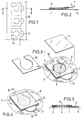
- Fig. 3 shows the application of a first embodiment on a measuring surface, e.g. a skin surface 9.
- a measuring surface e.g. a skin surface 9.
- a film carrier 12 double-sided adhesive films 7 with the help of a Tab 11 removed from the film carrier 12 and on the desired measuring point glued to the skin surface 9.
- the film 7 consists of a transparent flexible Plastic film with a thickness of approx. 0.4 to 0.7 mm, preferably about 0.5 mm, the one in the middle essentially circular punched out, which a essentially circular measuring field 4 limited. A further punching creates a drain channel 10 from the measuring field 4 to the outside.
- the films 7 arranged on the film carrier 12 have a cover paper 14, which after application the film 7 on the measuring surface, as shown in Fig. 3, can be removed.
- the disc 5 can be made of a thin, preferably anti-reflective Glass exist. When placing the disc 5 excess silicone material flows through the drainage channel 10 led to the outside, creating a pressure-free and therefore genuine silicone impression from the measuring surface can be produced. With a disc 5 out Glass suffices the weight of the pane to remove the excess Press out silicone material via the drain channel 10. After the silicone material has hardened 3 can the support plate 2, i.e. the film 7 together with the disc 5 and the silicone impression be pulled off the skin surface 9 and placed in an optical evaluation device.
- the adhesive surface of the carrier plate facing the skin surface 2 can be used to support the backing plate 2 stick on a frame 1, for example in slide projectors or video evaluation devices can be used and labeled in a suitable manner can be.
- the frame shows how Fig. 6 shows a circular in the middle Opening 16, which is adapted to the measuring field 4 and a Illuminate the carrier plate 2 with the silicone impression enables.
- Fig. 8, 9 and 10 show a frame 1 Carrier plate 2 of a second embodiment with integrated calibration device.
- liquid silicone layer enables a silicone impression a three-dimensional surface structure, in particular of skin folds on a human skin surface, to create.
- the frame 1 corresponds in terms of its dimensions exactly commercially available 35mm slide frames, so that the Silicone impression on the carrier plate 2 with the help of Slide projectors and video evaluation devices evaluated can be.
- the carrier plate 2 faces the measuring surface Page in the middle of the measuring field 4, from which a calibration device on one side of the measuring field 4 6 protrudes towards the measuring surface.
- the calibration device has a number of gradations 8 with exactly defined step distances, so that in Area of the calibration device 6 evenly solid colored silicone material in different stages Layer thickness is present.
- certain brightness values of the impression exact depth measurements be assigned.
- digitally evaluated differences in brightness can be calibrated exactly using the calibration device 6 be, so that a highly reproducible and accurate depth determination of the surface structure is possible.
- the Depth values of the surface structure are usually one Structural difference of maximum 0.5 mm.
- the even coloring of the silicone material is to the maximum layer thickness of the silicone layer of approx. 1 mm so that the resolution of the brightness values optimized for the measuring range of interest is.
- the side of the carrier plate facing away from the measuring surface 2 is preferably at least in the area of the measuring field 4 anti-reflective.
- the carrier plate 2 is undyed and exists made of glass or plastic. It can be anti-reflective be.
- the second embodiment run from outer edge of the measuring field 4 radially outward itself extending drainage channels 10 obliquely through the support plate 2 through.
- the slit-shaped drainage channels 10 expand radially outwards.
- the drainage channels 10 allow the drain of superfluous silicone material in making the impression and preventing so that in the area of the measuring field the measuring surface can build up changing pressure.
- the silicone material from the back the measuring field 4 diverted so that no silicone material can get to the back of the measuring field 4.
- the drainage channels 10 also serve to anchor the Silicone impression on the carrier plate 2, since the silicone impression evaluated on the carrier plate 2 remaining becomes.
Landscapes
- Health & Medical Sciences (AREA)
- Life Sciences & Earth Sciences (AREA)
- Physics & Mathematics (AREA)
- Medical Informatics (AREA)
- Surgery (AREA)
- Biophysics (AREA)
- Pathology (AREA)
- Engineering & Computer Science (AREA)
- Biomedical Technology (AREA)
- Heart & Thoracic Surgery (AREA)
- General Physics & Mathematics (AREA)
- Molecular Biology (AREA)
- Veterinary Medicine (AREA)
- Animal Behavior & Ethology (AREA)
- General Health & Medical Sciences (AREA)
- Public Health (AREA)
- Dermatology (AREA)
- Dentistry (AREA)
- Oral & Maxillofacial Surgery (AREA)
- Measurement Of The Respiration, Hearing Ability, Form, And Blood Characteristics Of Living Organisms (AREA)
- Length Measuring Devices With Unspecified Measuring Means (AREA)
- Length Measuring Devices By Optical Means (AREA)
- Investigating Or Analysing Materials By Optical Means (AREA)
Abstract
Claims (9)
- Dispositif permettant de mesurer une structure superficielle tridimensionnelle d'une surface de mesure (9), en particulier des plis de la peau d'un épiderme humain, comprenant une plaque support (2) transparente pour la réception d'une matière de prise d'empreinte tout d'abord liquide pour une empreinte de la surface de mesure (9), dans lequel la plaque support (2) présente un champ de mesure (4) qui est maintenu à une distance prédéterminée de la surface de mesure (9), et comprenant une unité d'évaluation pour évaluer la structure superficielle de l'empreinte, caractérisé par le fait que la matière liquide de prise d'empreinte à introduire dans le champ de mesure (4) se compose d'une matière silicone (3) uniformément colorée, et que la plaque support (2) comporte au moins un canal d'écoulement (10), partant du champ de mesure (4), pour le matière silicone (3) excédentaire.
- Dispositif selon la revendication 1, caractérisé par le fait que la plaque support (2) se compose d'une lame mince transparente (5) et d'une feuille (7) collante sur les deux faces, qui sert de support d'écartement et dans laquelle sont découpés le champ de mesure (4) et au moins un canal d'écoulement (10).
- Dispositif selon la revendication 1 ou 2, caractérisé par le fait qu'un dispositif de calibrage (6) en forme de gradins dirigé vers la surface de mesure (9), avec au moins deux écarts de gradin définis, est prévu à l'intérieur du champ de mesure (4).
- Dispositif selon la revendication 3, caractérisé par le fait que la matière silicone (3) est colorée avec une intensité si uniforme que pour chaque saut de gradin (8) du dispositif de calibrage (6) se produit une différence de luminosité mesurable avec une haute résolution.
- Dispositif selon l'une des revendications 1 ou 2, caractérisé par le fait que l'absorption de lumière de la matière silicone (3) par la coloration est choisie de telle sorte que 256 valeurs de luminosité sont différenciables concernant une épaisseur de couche maximale de matière silicone d'environ 1 mm.
- Dispositif selon l'une des revendications 1 à 3, caractérisé par le fait que la plaque support (2) est disposée dans un cadre (1) qui peut être placé dans des projecteurs de diapositive ou dans des dispositifs d'évaluation vidéo.
- Dispositif selon l'une des revendications 1 à 6, caractérisé par le fait que l'empreinte de silicone demeure sur la plaque support (2) pour l'évaluation.
- Dispositif selon l'une des revendications 1 à 7, caractérisé par le fait que des canaux d'écoulement (10) traversent la plaque support (2) à partir du bord du champ de mesure (4).
- Utilisation du dispositif selon les revendications 1 à 8, pour la mesure d'une structure superficielle tridimensionnelle d'une surface de mesure (9), en particulier des plis de la peau d'un épiderme humain, par préparation d'une empreinte de la surface de mesure (9) à l'aide de la plaque support transparente (2), la plaque support (2) étant retirée de la surface de mesure (9) après durcissement de la matière de prise d'empreinte, et l'empreinte durcie étant évaluée quant à la structure superficielle dans un dispositif d'évaluation optique, utilisation dans laquelle une matière silicone (3) uniformément colorée est utilisée comme matière de prise d'empreinte liquide, qui est mise en place sur la surface de mesure (9) délimitée par le champ de mesure (4), le champ de mesure (4) étant utilisé avec au moins un canal d'écoulement (10) pour la matière silicone (3) liquide excédentaire, cette matière silicone (3) excédentaire s'échappant du champ de mesure (4) par le canal d'écoulement (10).
Applications Claiming Priority (3)
| Application Number | Priority Date | Filing Date | Title |
|---|---|---|---|
| DE9303102U | 1993-03-03 | ||
| DE9303102U DE9303102U1 (de) | 1993-03-03 | 1993-03-03 | Vorrichtung zur messung einer dreidimensionalen oberflaechenstruktur |
| PCT/EP1994/000612 WO1994020019A1 (fr) | 1993-03-03 | 1994-03-02 | Procede et dispositif permettant de mesurer une structure superficielle tridimensionnelle |
Publications (2)
| Publication Number | Publication Date |
|---|---|
| EP0687162A1 EP0687162A1 (fr) | 1995-12-20 |
| EP0687162B1 true EP0687162B1 (fr) | 1998-01-14 |
Family
ID=6890136
Family Applications (1)
| Application Number | Title | Priority Date | Filing Date |
|---|---|---|---|
| EP94909104A Expired - Lifetime EP0687162B1 (fr) | 1993-03-03 | 1994-03-02 | Procede et dispositif permettant de mesurer une structure superficielle tridimensionnelle |
Country Status (5)
| Country | Link |
|---|---|
| US (1) | US5684573A (fr) |
| EP (1) | EP0687162B1 (fr) |
| JP (1) | JP3359343B2 (fr) |
| DE (2) | DE9303102U1 (fr) |
| WO (1) | WO1994020019A1 (fr) |
Families Citing this family (9)
| Publication number | Priority date | Publication date | Assignee | Title |
|---|---|---|---|---|
| GB9900973D0 (en) * | 1999-01-15 | 1999-03-10 | Remes Biomedical Limited | A method for objectively assessing the severity of scars in skin |
| FR2821541A1 (fr) * | 2001-03-02 | 2002-09-06 | Oreal | Procede d'evaluation du relief de la peau au moyen d'un support comportant une surface adhesive |
| US6937749B2 (en) * | 2001-03-02 | 2005-08-30 | L'oreal | Process, system, and kit for evaluating the relief of the skin with a substrate |
| US6926904B2 (en) * | 2001-05-30 | 2005-08-09 | Unilever Home & Personal Care Usa, Division Of Conopco, Inc. | Cosmetic product with proof device |
| US6875444B2 (en) * | 2001-05-30 | 2005-04-05 | Unilever Home & Personal Care Usa, Division Of Conopco, Inc. | Wrinkle indicator tape strip |
| CA2465507A1 (fr) * | 2002-06-12 | 2003-12-24 | Skinterface Sprl | Technique, procedes et dispositif permettant de retirer un element non adhesif de la peau d'etres vivants, de mesurer la perte d'elements pileux chez des etres vivants, d'etablir une echelle qualitative dun produit et de determiner le motif d'elements non adhesifs sur une surface |
| US6997046B2 (en) * | 2003-08-01 | 2006-02-14 | General Electric Company | Method and apparatus for fixtured wax and trace |
| US8157807B2 (en) | 2005-06-02 | 2012-04-17 | The Invention Science Fund I, Llc | Skin treatment including patterned light |
| US20060239547A1 (en) * | 2005-04-20 | 2006-10-26 | Robinson M R | Use of optical skin measurements to determine cosmetic skin properties |
Family Cites Families (7)
| Publication number | Priority date | Publication date | Assignee | Title |
|---|---|---|---|---|
| DE2719341C3 (de) * | 1977-04-30 | 1984-04-19 | Beiersdorf Ag, 2000 Hamburg | Verfahren zur meßtechnischen Bestimmung der Rauhigkeit der Oberfläche der menschlichen Haut |
| US4279482A (en) * | 1977-09-29 | 1981-07-21 | Redken Laboratories, Inc. | Illumination of replicas of biological surface tissue |
| JPS5943358A (ja) * | 1982-09-03 | 1984-03-10 | Kanebo Ltd | 皮膚表面形態の検査方法及び検査用具 |
| US4569358A (en) * | 1984-10-22 | 1986-02-11 | Gormley Daniel E | Optical micrometry of skin surfaces |
| FR2658713B1 (fr) * | 1990-02-27 | 1997-07-18 | Patrick Sevlian | Procede d'analyse du relief cutane, notamment dans le cas d'anomalies ou de variations de celui-ci. |
| US5211894A (en) * | 1990-10-09 | 1993-05-18 | Amway Corporation | Skin replication technique |
| DE4103353C1 (fr) | 1991-02-05 | 1992-08-27 | Thera Patent Gmbh & Co Kg Gesellschaft Fuer Industrielle Schutzrechte, 8031 Seefeld, De |
-
1993
- 1993-03-03 DE DE9303102U patent/DE9303102U1/de not_active Expired - Lifetime
-
1994
- 1994-03-02 JP JP51956094A patent/JP3359343B2/ja not_active Expired - Fee Related
- 1994-03-02 WO PCT/EP1994/000612 patent/WO1994020019A1/fr not_active Ceased
- 1994-03-02 DE DE59405037T patent/DE59405037D1/de not_active Expired - Fee Related
- 1994-03-02 EP EP94909104A patent/EP0687162B1/fr not_active Expired - Lifetime
- 1994-03-02 US US08/513,955 patent/US5684573A/en not_active Expired - Lifetime
Also Published As
| Publication number | Publication date |
|---|---|
| DE59405037D1 (de) | 1998-02-19 |
| JP3359343B2 (ja) | 2002-12-24 |
| EP0687162A1 (fr) | 1995-12-20 |
| DE9303102U1 (de) | 1993-08-05 |
| JPH08509624A (ja) | 1996-10-15 |
| WO1994020019A1 (fr) | 1994-09-15 |
| US5684573A (en) | 1997-11-04 |
Similar Documents
| Publication | Publication Date | Title |
|---|---|---|
| DE2613617C2 (de) | Verfahren zur Analyse von Proben, z.B. Urin | |
| DE69632739T2 (de) | Vorrichtung zur fixierung von messbedingungen | |
| DE69221306T2 (de) | Methode zur photometrischen (in vitro) bestimmung des gehaltes eines analyts in einer probe | |
| EP0997104B1 (fr) | Dispositif de mesure des paramètres de la peau | |
| EP0777119A2 (fr) | Appareil pour des mesures de réflexion de la lumière | |
| DE102015113557B4 (de) | Probenvorrichtung mit Referenzmarkierung | |
| EP0376110B1 (fr) | Analyseur pour bandes de test | |
| DE3033870C2 (de) | Vorrichtung zum Nachweis von immunologischen Agglutinationsmustern | |
| DE4136025C2 (de) | Verfahren zum Unterscheiden eines Teilchenagglutinationsmusters | |
| DE2737554A1 (de) | Vorrichtung zur haertepruefung | |
| EP0687162B1 (fr) | Procede et dispositif permettant de mesurer une structure superficielle tridimensionnelle | |
| EP2409125B1 (fr) | Procédé et dispositif pour effectuer une comparaison optique entre au moins deux modèles, de préférence par comparaison d'extraits sélectionnables | |
| EP0812153B1 (fr) | Systeme de mesure permettant de determiner la secretion de sebum de la peau | |
| DE4038123A1 (de) | Differentialrefraktometer | |
| DE4424112A1 (de) | Verfahren zur Herstellung eines Probenträgers | |
| DE1673168B2 (de) | Verfahren und Vorrichtung zum Untersuchen und Registrieren des Gehaltes von Luft- und Gasproben an Feststoffteilchen | |
| DE2004707B2 (de) | Cromatografieplatte für die Dünnschichtchromatografie | |
| DE19720864C2 (de) | Verfahren und Vorrichtung zur zerstörungsfreien Bestimmung der Elastizität von Materialien | |
| DE4337528A1 (de) | Verfahren zur Zustandsfeststellung an Hautgewebe | |
| WO2001042772A1 (fr) | Procede de controle de la qualite de couches de matiere | |
| WO2019008461A1 (fr) | Dispositif et procédé pour acquérir des informations au moins 2d relatives à des analytes et élément de détection à cet effet | |
| DE68918417T2 (de) | Körper mit Spiegeloberfläche zur Projektion latenter Bilder. | |
| DE3902348C2 (fr) | ||
| DE102015109263A1 (de) | Messsystem zur Qualitätsüberwachung von Prüflingen | |
| DE69429553T2 (de) | Verfahren and Gerät zur mikroskopischen Abbildung |
Legal Events
| Date | Code | Title | Description |
|---|---|---|---|
| PUAI | Public reference made under article 153(3) epc to a published international application that has entered the european phase |
Free format text: ORIGINAL CODE: 0009012 |
|
| 17P | Request for examination filed |
Effective date: 19950810 |
|
| AK | Designated contracting states |
Kind code of ref document: A1 Designated state(s): DE FR GB IT |
|
| 17Q | First examination report despatched |
Effective date: 19960607 |
|
| GRAG | Despatch of communication of intention to grant |
Free format text: ORIGINAL CODE: EPIDOS AGRA |
|
| GRAG | Despatch of communication of intention to grant |
Free format text: ORIGINAL CODE: EPIDOS AGRA |
|
| GRAH | Despatch of communication of intention to grant a patent |
Free format text: ORIGINAL CODE: EPIDOS IGRA |
|
| GRAH | Despatch of communication of intention to grant a patent |
Free format text: ORIGINAL CODE: EPIDOS IGRA |
|
| GRAA | (expected) grant |
Free format text: ORIGINAL CODE: 0009210 |
|
| AK | Designated contracting states |
Kind code of ref document: B1 Designated state(s): DE FR GB IT |
|
| REF | Corresponds to: |
Ref document number: 59405037 Country of ref document: DE Date of ref document: 19980219 |
|
| ET | Fr: translation filed | ||
| ITF | It: translation for a ep patent filed | ||
| GBT | Gb: translation of ep patent filed (gb section 77(6)(a)/1977) |
Effective date: 19980318 |
|
| PLBE | No opposition filed within time limit |
Free format text: ORIGINAL CODE: 0009261 |
|
| STAA | Information on the status of an ep patent application or granted ep patent |
Free format text: STATUS: NO OPPOSITION FILED WITHIN TIME LIMIT |
|
| 26N | No opposition filed | ||
| REG | Reference to a national code |
Ref country code: GB Ref legal event code: IF02 |
|
| PGFP | Annual fee paid to national office [announced via postgrant information from national office to epo] |
Ref country code: GB Payment date: 20040209 Year of fee payment: 11 |
|
| PG25 | Lapsed in a contracting state [announced via postgrant information from national office to epo] |
Ref country code: IT Free format text: LAPSE BECAUSE OF NON-PAYMENT OF DUE FEES Effective date: 20050302 Ref country code: GB Free format text: LAPSE BECAUSE OF NON-PAYMENT OF DUE FEES Effective date: 20050302 |
|
| GBPC | Gb: european patent ceased through non-payment of renewal fee |
Effective date: 20050302 |
|
| PGFP | Annual fee paid to national office [announced via postgrant information from national office to epo] |
Ref country code: DE Payment date: 20090525 Year of fee payment: 16 |
|
| PGFP | Annual fee paid to national office [announced via postgrant information from national office to epo] |
Ref country code: FR Payment date: 20090318 Year of fee payment: 16 |
|
| REG | Reference to a national code |
Ref country code: FR Ref legal event code: ST Effective date: 20101130 |
|
| PG25 | Lapsed in a contracting state [announced via postgrant information from national office to epo] |
Ref country code: FR Free format text: LAPSE BECAUSE OF NON-PAYMENT OF DUE FEES Effective date: 20100331 |
|
| PG25 | Lapsed in a contracting state [announced via postgrant information from national office to epo] |
Ref country code: DE Free format text: LAPSE BECAUSE OF NON-PAYMENT OF DUE FEES Effective date: 20101001 |