EP0687218B1 - Ausrüstung die eine pressrolle enthält zum zusammenpressen von abfall - Google Patents
Ausrüstung die eine pressrolle enthält zum zusammenpressen von abfall Download PDFInfo
- Publication number
- EP0687218B1 EP0687218B1 EP93909119A EP93909119A EP0687218B1 EP 0687218 B1 EP0687218 B1 EP 0687218B1 EP 93909119 A EP93909119 A EP 93909119A EP 93909119 A EP93909119 A EP 93909119A EP 0687218 B1 EP0687218 B1 EP 0687218B1
- Authority
- EP
- European Patent Office
- Prior art keywords
- arrangement
- roller
- vessel
- compacting
- accordance
- Prior art date
- Legal status (The legal status is an assumption and is not a legal conclusion. Google has not performed a legal analysis and makes no representation as to the accuracy of the status listed.)
- Expired - Lifetime
Links
- 239000010813 municipal solid waste Substances 0.000 title description 4
- 239000000463 material Substances 0.000 claims abstract description 25
- 238000005056 compaction Methods 0.000 claims description 11
- 230000000694 effects Effects 0.000 description 3
- 239000012530 fluid Substances 0.000 description 2
- 230000000295 complement effect Effects 0.000 description 1
- 238000006073 displacement reaction Methods 0.000 description 1
- 239000002184 metal Substances 0.000 description 1
- 238000005192 partition Methods 0.000 description 1
- 238000003466 welding Methods 0.000 description 1
Images




Classifications
-
- B—PERFORMING OPERATIONS; TRANSPORTING
- B30—PRESSES
- B30B—PRESSES IN GENERAL
- B30B9/00—Presses specially adapted for particular purposes
- B30B9/30—Presses specially adapted for particular purposes for baling; Compression boxes therefor
- B30B9/3082—Presses specially adapted for particular purposes for baling; Compression boxes therefor with compression means other than rams performing a rectilinear movement
Definitions
- the present invention relates to an arrangement for a compacting plant for refuse and similar material, which comprises a drivable rotating roller for compacting the material inside a receiver vessel and capable of moving in an essentially horizontal direction about an essentially vertical shaft, preferably driven in a rotary fashion, which roller can be supported enabling it to be moved in a direction between the bottom of the vessel and its upper part.
- the known arrangement for a compacting plant for refuse and similar material comprises a drivable rotating roller for compacting the material inside a receiver vessel.
- the roller is capable of moving in an essentially horizontal direction about an essentially vertical shaft.
- the vertical shaft is movable in a direction between the bottom of the vessel and its upper part by means of a lifting device comprising a gear-rack engaged by a pinion.
- SE-B-399,208 is disclosed an apparatus for compacting goods like trash in a container comprising a plunger movable upwards and downwards in a container by means of a driving mechanism.
- a problem associated with compacting plants of the kind referred to above is the need to be able to achieve even compaction along essentially the whole of the material accommodating space of a vessel, and to be able to support a compaction roller by simple, yet effective and reliable means.
- the supports for the roller in these previously disclosed compactors are unnecessarily complex and temperamental in use, for example arms capable of being transported on carriages in upright guide tracks, with the result that large spaces are required in the area above the material receiver vessel.
- the principal object of the present invention is thus, in the first place, to enable at least one of the problems and disadvantages referred to above to be solved by simple and efficient means.
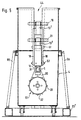
- An arrangement 1 for use in a compacting plant 2 intended for refuse T or similar material which comprises at least one drivable rotating roller 32 for compacting the material inside a receiver vessel 4 in an essentially horizontal direction, in conjunction with which the roller 32 is capable of moving about an essentially vertical shaft 5, preferably driven in a rotary fashion so that the material is compacted by the roller 32, which roller is so arranged as to be supported enabling it to be moved in a 30 vertical direction 6, 7 between the bottom 8 of the vessel and its upper part 9, in conjunction with which said vertical rotating shaft 5 is supported so as to be capable of lateral displacement.
- said vertical, preferably rotating shaft 5 4 can be supported telescopically as shown in Fig. 13 (not part of the invention as claimed), by a telescope 150.
- the vertical, preferably rotating shaft 5, which supports a roller support arm 10 extending laterally and preferably obliquely downwards towards the outside 4A of the vessel, is supported by a pivot arm arrangement 11.
- Said pivot arm arrangement 11 is formed preferably by pairs of arms 12, 13, which can be divided laterally into double arm parts 12, 12B; 13A, 13B situated at a mutual distance X and displaced laterally from one another.
- Said pairs of arms 12, 13 are preferably arranged in parallel, with one arm 12 positioned at a level higher than the other arm 13 and above same at a mutual distance Y from one another, in the form of so-called parallel tie rods, which arms 12, 13 are connected to one another.
- connection 14 is formed in that the arms 12, 13 are pivotally connected, when viewed in the vertical sense, to a pivot shaft attachment 15 and to a support point 16 for the toned roller arrangement 17, via a parallel link 18 and swivel joints 19, 20, 21, 22.
- a jack 25 or some other means of transmitting force is so arranged as to be capable of actuating said pivot arms 12, 13, in conjunction with which the preferably hydraulically driven piston cylinder arrangement 25 acts between the swivel joint attachment 26 on one arm 13 and a swivel joint 27 in a fixed position, for example on the frame upright 24 or a wall.
- the illustrative embodiment of a compacting plant 2 1 and an arrangement 1 1 differs from the previous example primarily through the design of the lifting arms 12 1 , 13 1 . These are executed bent or curved and formed like a fork at one end with pairs of side arm parts 12A 1 , 12B 1 ; 13A 1 , 13B 1 , between which a hydraulically acting swivel 28 is accommodated for the purpose of supporting and driving the arm 10 and the roller arrangement 17 in the event of the arrangement being designed to exhibit a roller capable of rotating about the vertical shaft.
- the attachments 15, 29 for the swivel 28 are also attached to the links 18.
- the roller arrangement 17 is supported via a supporting plate 30 at the lower end 10A of the roller support arm 10, which is preferably inclined at an angle downwards and outwards from the rotating shaft 5, whilst the shaft 5 is attached to the upper end 10B of the arm via screwed connections 31, etc.
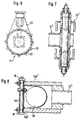
- the compacting roller 32 can be divided, in conjunction with which one cylindrical part 32A of the roller is passed over a further cylindrical part 32B of the roller.
- One 32A of the two roller parts 32A, 32B can exhibit a number of shredding teeth 33 or other compaction/pressure/tearing devices, whilst the other part 32B of the roller, which is attached to the support plate 30, for example by welding, can form a bearing support for the roller part 32A.
- a preferably hydraulic drive motor 34 Accommodated internally in the roller 32 is a preferably hydraulic drive motor 34, which is supported by an end plate 35 on the inner part 32B of the roller and is connected with the drive shaft 36 to an internal partition wall 37 in the outer part 32A of the roller.
- Hydraulic fluid is transferred via the swivel 28, the arm 10 and the plate 30 to the motor 34 for the purpose of driving the roller 32 and compacting the material T in the vessel 4 as the arm 10 is caused to pivot with the help of and about the shaft 5.
- the roller arrangement 17 is appropriately raised through the effect of the jack 25 until the vessel 4 is filled with finally compacted material T.
- the arms 12, 13; 12 1 , 13 1 are caused to pivot for this purpose along corresponding pivot paths 37, 38; 37 1 , 38 1 .
- the design of the lifting arms 12 1 , 13 1 with an angled central part 53, 54 means that the total pivot height for the arms 12 1 , 13 1 can be kept low, and that the total height is thus small, even with the arms 12 1 , 13 1 pivoted fully upwards when replacing the vessel 4, which is advantageous in refuse rooms with a low ceiling height.
- Side supports 55, 56 for the vessel 4 may be provided, for example in the form of struts, and may be attached to a frame 23 1 .
- the vessel 4 is introduced between the supports 55, 56 and is held in position by them during compaction.
- a receiving arrangement 42, 42 1 may be connected to the upper material opening 43 of the vessel, in conjunction with which a slot 44 to accommodate the roller lift arms 12, 13; 12 1 , 13 1 is situated in it, for example as shown in Fig. 5.
- Fig. 10 shows a top view of a plant 2 2 of circular vessel form, i.e. sacks 4 2 made of a plastic material, for example, are so arranged as to be capable of being accommodated inside an outer layer 57 of hard material, in conjunction with which said outer layer can be parted at an opening 58 and can be swung out of the way about swivel joints 59, 60 to permit the sack 4 2 to be replaced.
- Fig. 9 shows a top view of a plant 2 1 with square container walls 4 1 , which may be tippable by means of the lifting gear on the refuse collection vehicle.
- Fig. 11 shows a variant of the plant 2 3 with a vessel in the form of, for example, an upwardly open container 4 3 .
- a support arrangement in the form of, for example, uprights 101 or other raised elements 101 3 with tracks 102, 102 3 can be arranged along one long side 100 of said container and can be attached, for example, to a support 103 capable of being positioned beneath the container 4 3 .
- the vertical shaft 5 3 which at its lower end supports a transverse driveable compaction roller 104, to be supported in such a way as to be capable of being displaced and, should the occasion arise, as to be capable of being caused to rotate along the material receiving vessel about said vertical shaft 5 3 .
- the vertical shaft 5 3 is supported by a pivot arm arrangement 11 3 , which is connected to a carrier 105, 105 3 capable of moving along a path, preferably a carriage attached to tracks 102, 102 3 extending along the vessel 4 3 .
- This compaction roller 104 can thus be driven in the longitudinal sense of the container along the path when the arms 12 3 , 13 3 are supported by the carriage/carriages 105, 105 3 and caused to move along said tracks 102, 102 3 , with the rotating effect of the roller 104 both about the vertical axis 5 3 in the direction 106, 107 and about a horizontal axis of rotation 108.
- Lifting of the arms 12 3 , 13 3 and the roller 104 can also be achieved by means of a jack 25 3 , as in previous examples.
- the driving effect of the roller 104 from the outside of the container can also take place, for example, by means of a toothed rail or some other driving means running along the track.
- Fig. 13 shows a variant of an arrangement 2 4 (not part of the invention as claimed) in which the vertical and preferably pivotable shaft 5 4 , which supports a supporting arm 10 extending laterally towards the outside of the vessel, is supported by a portal superstructure 151 extending over the upper part of a moving material receiving vessel 4 4 via a number of suspended lifting arms 152, 153, 154 capable of being accommodated lengthwise along-side one another.
- the lifting arms can be formed from sleeves capable of telescoping into one another and with internally accommodated hydraulic lines, etc., for the supply of the fluid for driving the roller.
Landscapes
- Engineering & Computer Science (AREA)
- Mechanical Engineering (AREA)
- Processing Of Solid Wastes (AREA)
- Refuse Receptacles (AREA)
- Spinning Or Twisting Of Yarns (AREA)
- Refuse Collection And Transfer (AREA)
- Paper (AREA)
- Press Drives And Press Lines (AREA)
- Road Paving Machines (AREA)
Claims (7)
- Anordnung (1; 11) für eine Verdichtungseinrichtung für Abfall und ähnliches Material, die eine antreibbare, sich drehende Walze (32; 104) zur Verdichtung des Materials innerhalb eines Aufnahmebehältnisses (4; 42; 43) aufweist und zur Bewegung in einer im wesentlichen horizontalen Richtung um eine in wesentlichen vertikale, vorzugsweise zu einer Drehung antreibbaren Welle (5; 53) eingerichtet ist, wobei die Walze so gehalten wird, daß sie in einer Richtung zwischen dem Boden des Behältnisses und dessen oberen Teil bewegt werden kann, dadurch gekennzeichnet, daß die vertikale, vorzugsweise sich drehende Welle so gehalten wird, daß sie sich mittels einer Schwenkarmanordnung (11; 113), die durch Paare von Armen (12, 13; 121, 131: 123, 133) gebildet ist, die in einem gegenseitigen Abstand (Y) voneinander angeordnet sind, seitlich (39, 40) bewegen kann.
- Anordnung gemäß Anspruch 1, dadurch gekennzeichnet, daß die vertikale Welle (5), die einen sich zu der Außenseite (4A) des Behältnisses erstreckenden Walzenhaltearm (10) hält, durch eine Schwenkarmanordnung (11) gehalten wird, die durch Paare von Armen (12, 13) gebildet wird, die parallel in einem gegenseitigen Abstand (Y) voneinander in der Gestalt von sogenannten parallelen Spurstangen angeordnet sind.
- Anordnung gemäß Anspruch 1 oder 2, dadurch gekennzeichnet, daß die Arme (12, 13) mit Ansicht in vertikaler Richtung schwenkbar an einer Scbwenkwellenbefestigung (19-22) und an einem Haltebereich (16) für die ausgebildete Walzenanordnung (17) angebracht sind.
- Anordnung gemäß Anspruch 3, dadurch gekennzeichnet, daß ein aufrechter Rahmen (24) oder eine fixierte Befestigung wie eine Wand als Haltebereich dient.
- Anordnung gemäß Anspruch 1, dadurch gekennzeichnet, daß die vertikale Welle (53), die an ihrem unteren Ende eine sich quer erstreckende Verdichterwalze (104) hält, so gehalten wird, daß sie entlang des materialaufnehmenden Behältnisses (43) bewegbar ist (Fig. 11).
- Anordnung gemäß Anspruch 5, dadurch gekennzeichnet, daß die Schwenkarmanordnung (113) an einem Träger (105) angebracht ist, der entlang eines Wegs bewegbar ist, vorzugsweise an einem an sich entlang des Behältnisses erstreckenden Führungen (102) angebrachten Wagen.
- Anordnung gemäß einem oder mehreren der voranstehenden Ansprüche, dadurch gekennzeichnet, daß ein Arbeitszylinder (25; 253) oder ein anderes Mittel zur Kraftübertragung zur Betätigung des Schwenkarms (13, 133) eingerichtet ist.
Applications Claiming Priority (3)
| Application Number | Priority Date | Filing Date | Title |
|---|---|---|---|
| SE9201171 | 1992-04-13 | ||
| SE9201171A SE470180B (sv) | 1992-04-13 | 1992-04-13 | Avfallspress innefattande företrädesvis vridbart driven vals upphängd i svängarmsarrangemang |
| PCT/SE1993/000309 WO1993021007A1 (en) | 1992-04-13 | 1993-04-08 | Equipment for compacting trash including a compacting roller |
Publications (2)
| Publication Number | Publication Date |
|---|---|
| EP0687218A1 EP0687218A1 (de) | 1995-12-20 |
| EP0687218B1 true EP0687218B1 (de) | 1999-12-22 |
Family
ID=20385944
Family Applications (1)
| Application Number | Title | Priority Date | Filing Date |
|---|---|---|---|
| EP93909119A Expired - Lifetime EP0687218B1 (de) | 1992-04-13 | 1993-04-08 | Ausrüstung die eine pressrolle enthält zum zusammenpressen von abfall |
Country Status (10)
| Country | Link |
|---|---|
| US (1) | US5492056A (de) |
| EP (1) | EP0687218B1 (de) |
| JP (1) | JPH07508220A (de) |
| AT (1) | ATE187921T1 (de) |
| AU (1) | AU3965293A (de) |
| CA (1) | CA2117908A1 (de) |
| DE (1) | DE69327404T2 (de) |
| NO (1) | NO303532B1 (de) |
| SE (1) | SE470180B (de) |
| WO (1) | WO1993021007A1 (de) |
Families Citing this family (7)
| Publication number | Priority date | Publication date | Assignee | Title |
|---|---|---|---|---|
| SE502933C2 (sv) * | 1994-03-23 | 1996-02-26 | Sebastian Hansen | Anordning vid komprimator för sammanpackning av gods |
| FR2769900B1 (fr) * | 1997-10-16 | 1999-12-31 | Antoine Marie Chedru | Dispositif de reduction du volume de dechets |
| FR2802462B1 (fr) | 1999-12-18 | 2002-03-01 | Valdec | Procede de compactage de dechets et machine pour sa mise en oeuvre |
| FR2823695B1 (fr) * | 2001-04-19 | 2003-08-15 | Valdec | Tete de compactage de dechets |
| DE102008019305A1 (de) * | 2008-04-16 | 2009-10-29 | Heinz Bergmann Maschinen für die Abfallwirtschaft e.Kfm | Modulare, mobile Einheit, die einem nach oben offenen Container als Abfallverdichter zugeordnet werden kann |
| DE202014105681U1 (de) | 2014-11-25 | 2016-02-26 | Husmann Umwelt-Technik Gmbh | Transportabler Rollenverdichter |
| FR3110486B1 (fr) * | 2020-05-20 | 2022-05-27 | Tech Negoce | Rouleau, dispositif et procédé de compactage de déchets |
Family Cites Families (6)
| Publication number | Priority date | Publication date | Assignee | Title |
|---|---|---|---|---|
| US3720052A (en) * | 1971-05-03 | 1973-03-13 | Haybuster Mfg Inc | Haystacking machine |
| DE2431109C2 (de) * | 1974-06-28 | 1975-12-11 | Bosch-Siemens Hausgeraete Gmbh, 7000 Stuttgart | Gerät zum Zusammenpressen von sperrigem Gut, insbesondere Haushalts-Müllverdichter |
| DE3166299D1 (en) * | 1980-06-24 | 1984-10-31 | Heinz Bergmann | Device to compact refuse in open containers |
| SU934984A2 (ru) * | 1980-12-11 | 1982-06-15 | Всероссийский Ордена Трудового Красного Знамени Научно-Исследовательский И Проектно-Технологический Институт Механизации И Электрификации Сельского Хозяйства | Стогообразователь |
| DE3326007A1 (de) * | 1982-10-15 | 1984-04-19 | Heinz 4474 Lathen Bergmann | Vorrichtung zum verdichten von aus verpackungsmaterial und leicht pressbaren abfaellen bestehenden muell |
| DE3406879A1 (de) * | 1984-02-25 | 1985-08-29 | Heinz 4474 Lathen Bergmann | Vorrichtung zum verdichten von aus verpackungsmaterial und leicht pressbaren abfaellen bestehendem muell |
-
1992
- 1992-04-13 SE SE9201171A patent/SE470180B/sv not_active IP Right Cessation
-
1993
- 1993-04-08 CA CA002117908A patent/CA2117908A1/en not_active Abandoned
- 1993-04-08 JP JP5518235A patent/JPH07508220A/ja active Pending
- 1993-04-08 AT AT93909119T patent/ATE187921T1/de not_active IP Right Cessation
- 1993-04-08 US US08/318,634 patent/US5492056A/en not_active Expired - Fee Related
- 1993-04-08 EP EP93909119A patent/EP0687218B1/de not_active Expired - Lifetime
- 1993-04-08 AU AU39652/93A patent/AU3965293A/en not_active Abandoned
- 1993-04-08 WO PCT/SE1993/000309 patent/WO1993021007A1/en not_active Ceased
- 1993-04-08 DE DE69327404T patent/DE69327404T2/de not_active Expired - Fee Related
-
1994
- 1994-10-13 NO NO943865A patent/NO303532B1/no not_active IP Right Cessation
Also Published As
| Publication number | Publication date |
|---|---|
| CA2117908A1 (en) | 1993-10-28 |
| AU3965293A (en) | 1993-11-18 |
| DE69327404T2 (de) | 2000-05-04 |
| SE470180B (sv) | 1993-11-29 |
| NO303532B1 (no) | 1998-07-27 |
| ATE187921T1 (de) | 2000-01-15 |
| EP0687218A1 (de) | 1995-12-20 |
| NO943865D0 (no) | 1994-10-13 |
| US5492056A (en) | 1996-02-20 |
| JPH07508220A (ja) | 1995-09-14 |
| NO943865L (no) | 1994-10-13 |
| DE69327404D1 (de) | 2000-01-27 |
| WO1993021007A1 (en) | 1993-10-28 |
| SE9201171L (sv) | 1993-10-14 |
| SE9201171D0 (sv) | 1992-04-13 |
Similar Documents
| Publication | Publication Date | Title |
|---|---|---|
| US4422814A (en) | Ground level dump unit | |
| CA2591262C (en) | Automated loader | |
| US5049026A (en) | Refuse collection and loading system | |
| USRE34292E (en) | Refuse collection and loading system | |
| US4872801A (en) | Side refuse loader for vehicles | |
| DE3123161C2 (de) | ||
| US6761523B2 (en) | Mechanism for dumping a refuse container | |
| US3666126A (en) | Fruit container pickup vehicle | |
| US3822802A (en) | Refuse collector | |
| US5026241A (en) | Apparatus and method for dumping a waste receptacle | |
| US5492056A (en) | Apparatus for compacting refuse material in a vessel | |
| US4249848A (en) | Transportable, collapsible vehicle loading hopper | |
| US3691967A (en) | Mobile refuse compacting apparatus | |
| DE4005968A1 (de) | Muellsammelfahrzeug | |
| US3179264A (en) | Rake crane | |
| US4061179A (en) | Apparatus for pouring casting material | |
| CN212739871U (zh) | 一种集装箱的超细粉装箱装置 | |
| US3007264A (en) | Railroad track ballast dressing machine | |
| CN115676193B (zh) | 一种垃圾桶翻转机 | |
| EP0315674B1 (de) | Vorrichtung zum verdichten von abfall od.dgl. in einem behälter | |
| DE3830989A1 (de) | Hubkippvorrichtung zum entleeren von muellbehaeltern in ein sammelfahrzeug | |
| US5365837A (en) | Apparatus for packing material in an open top container | |
| US5295780A (en) | Dumping apparatus for bag filled with molten substance | |
| ITTO20000318A1 (it) | Dispositivo per la movimentazione e lo scarico del contenuto, di contenitori adibiti alla raccolta dei rifiuti. | |
| US4988257A (en) | Device for handling refuse |
Legal Events
| Date | Code | Title | Description |
|---|---|---|---|
| PUAI | Public reference made under article 153(3) epc to a published international application that has entered the european phase |
Free format text: ORIGINAL CODE: 0009012 |
|
| 17P | Request for examination filed |
Effective date: 19941010 |
|
| AK | Designated contracting states |
Kind code of ref document: A1 Designated state(s): AT BE CH DE DK ES FR GB GR IE IT LI LU MC NL PT SE |
|
| 17Q | First examination report despatched |
Effective date: 19980223 |
|
| GRAG | Despatch of communication of intention to grant |
Free format text: ORIGINAL CODE: EPIDOS AGRA |
|
| GRAG | Despatch of communication of intention to grant |
Free format text: ORIGINAL CODE: EPIDOS AGRA |
|
| GRAH | Despatch of communication of intention to grant a patent |
Free format text: ORIGINAL CODE: EPIDOS IGRA |
|
| GRAH | Despatch of communication of intention to grant a patent |
Free format text: ORIGINAL CODE: EPIDOS IGRA |
|
| GRAA | (expected) grant |
Free format text: ORIGINAL CODE: 0009210 |
|
| AK | Designated contracting states |
Kind code of ref document: B1 Designated state(s): AT BE CH DE DK ES FR GB GR IE IT LI LU MC NL PT SE |
|
| PG25 | Lapsed in a contracting state [announced via postgrant information from national office to epo] |
Ref country code: SE Free format text: THE PATENT HAS BEEN ANNULLED BY A DECISION OF A NATIONAL AUTHORITY Effective date: 19991222 Ref country code: NL Free format text: LAPSE BECAUSE OF FAILURE TO SUBMIT A TRANSLATION OF THE DESCRIPTION OR TO PAY THE FEE WITHIN THE PRESCRIBED TIME-LIMIT Effective date: 19991222 Ref country code: LI Free format text: LAPSE BECAUSE OF FAILURE TO SUBMIT A TRANSLATION OF THE DESCRIPTION OR TO PAY THE FEE WITHIN THE PRESCRIBED TIME-LIMIT Effective date: 19991222 Ref country code: IT Free format text: LAPSE BECAUSE OF FAILURE TO SUBMIT A TRANSLATION OF THE DESCRIPTION OR TO PAY THE FEE WITHIN THE PRE;WARNING: LAPSES OF ITALIAN PATENTS WITH EFFECTIVE DATE BEFORE 2007 MAY HAVE OCCURRED AT ANY TIME BEFORE 2007. THE CORRECT EFFECTIVE DATE MAY BE DIFFERENT FROM THE ONE RECORDED.SCRIBED TIME-LIMIT Effective date: 19991222 Ref country code: GR Free format text: LAPSE BECAUSE OF NON-PAYMENT OF DUE FEES Effective date: 19991222 Ref country code: FR Free format text: LAPSE BECAUSE OF FAILURE TO SUBMIT A TRANSLATION OF THE DESCRIPTION OR TO PAY THE FEE WITHIN THE PRESCRIBED TIME-LIMIT Effective date: 19991222 Ref country code: ES Free format text: THE PATENT HAS BEEN ANNULLED BY A DECISION OF A NATIONAL AUTHORITY Effective date: 19991222 Ref country code: CH Free format text: LAPSE BECAUSE OF FAILURE TO SUBMIT A TRANSLATION OF THE DESCRIPTION OR TO PAY THE FEE WITHIN THE PRESCRIBED TIME-LIMIT Effective date: 19991222 Ref country code: BE Free format text: LAPSE BECAUSE OF FAILURE TO SUBMIT A TRANSLATION OF THE DESCRIPTION OR TO PAY THE FEE WITHIN THE PRESCRIBED TIME-LIMIT Effective date: 19991222 Ref country code: AT Free format text: LAPSE BECAUSE OF FAILURE TO SUBMIT A TRANSLATION OF THE DESCRIPTION OR TO PAY THE FEE WITHIN THE PRESCRIBED TIME-LIMIT Effective date: 19991222 |
|
| REF | Corresponds to: |
Ref document number: 187921 Country of ref document: AT Date of ref document: 20000115 Kind code of ref document: T |
|
| REG | Reference to a national code |
Ref country code: CH Ref legal event code: EP |
|
| REF | Corresponds to: |
Ref document number: 69327404 Country of ref document: DE Date of ref document: 20000127 |
|
| REG | Reference to a national code |
Ref country code: IE Ref legal event code: FG4D |
|
| PG25 | Lapsed in a contracting state [announced via postgrant information from national office to epo] |
Ref country code: PT Free format text: LAPSE BECAUSE OF FAILURE TO SUBMIT A TRANSLATION OF THE DESCRIPTION OR TO PAY THE FEE WITHIN THE PRESCRIBED TIME-LIMIT Effective date: 20000322 Ref country code: DK Free format text: LAPSE BECAUSE OF FAILURE TO SUBMIT A TRANSLATION OF THE DESCRIPTION OR TO PAY THE FEE WITHIN THE PRESCRIBED TIME-LIMIT Effective date: 20000322 |
|
| PG25 | Lapsed in a contracting state [announced via postgrant information from national office to epo] |
Ref country code: LU Free format text: LAPSE BECAUSE OF NON-PAYMENT OF DUE FEES Effective date: 20000408 Ref country code: GB Free format text: LAPSE BECAUSE OF NON-PAYMENT OF DUE FEES Effective date: 20000408 |
|
| EN | Fr: translation not filed | ||
| NLV1 | Nl: lapsed or annulled due to failure to fulfill the requirements of art. 29p and 29m of the patents act | ||
| REG | Reference to a national code |
Ref country code: CH Ref legal event code: PL |
|
| PLBE | No opposition filed within time limit |
Free format text: ORIGINAL CODE: 0009261 |
|
| STAA | Information on the status of an ep patent application or granted ep patent |
Free format text: STATUS: NO OPPOSITION FILED WITHIN TIME LIMIT |
|
| PG25 | Lapsed in a contracting state [announced via postgrant information from national office to epo] |
Ref country code: MC Free format text: LAPSE BECAUSE OF NON-PAYMENT OF DUE FEES Effective date: 20001031 |
|
| GBPC | Gb: european patent ceased through non-payment of renewal fee |
Effective date: 20000408 |
|
| 26N | No opposition filed | ||
| PGFP | Annual fee paid to national office [announced via postgrant information from national office to epo] |
Ref country code: IE Payment date: 20030430 Year of fee payment: 11 |
|
| PGFP | Annual fee paid to national office [announced via postgrant information from national office to epo] |
Ref country code: DE Payment date: 20030522 Year of fee payment: 11 |
|
| PG25 | Lapsed in a contracting state [announced via postgrant information from national office to epo] |
Ref country code: IE Free format text: LAPSE BECAUSE OF NON-PAYMENT OF DUE FEES Effective date: 20040408 |
|
| PG25 | Lapsed in a contracting state [announced via postgrant information from national office to epo] |
Ref country code: DE Free format text: LAPSE BECAUSE OF NON-PAYMENT OF DUE FEES Effective date: 20041103 |
|
| REG | Reference to a national code |
Ref country code: IE Ref legal event code: MM4A |