EP0687237B1 - Vorrichtung zum konditionieren von gegenständen - Google Patents
Vorrichtung zum konditionieren von gegenständen Download PDFInfo
- Publication number
- EP0687237B1 EP0687237B1 EP94908694A EP94908694A EP0687237B1 EP 0687237 B1 EP0687237 B1 EP 0687237B1 EP 94908694 A EP94908694 A EP 94908694A EP 94908694 A EP94908694 A EP 94908694A EP 0687237 B1 EP0687237 B1 EP 0687237B1
- Authority
- EP
- European Patent Office
- Prior art keywords
- article
- articles
- path
- exit
- shuttle
- Prior art date
- Legal status (The legal status is an assumption and is not a legal conclusion. Google has not performed a legal analysis and makes no representation as to the accuracy of the status listed.)
- Expired - Lifetime
Links
- 230000000694 effects Effects 0.000 claims abstract description 4
- 239000007787 solid Substances 0.000 abstract description 4
- 239000011888 foil Substances 0.000 description 3
- 230000037361 pathway Effects 0.000 description 3
- 230000003028 elevating effect Effects 0.000 description 2
- 238000004806 packaging method and process Methods 0.000 description 2
- 230000008676 import Effects 0.000 description 1
- NJPPVKZQTLUDBO-UHFFFAOYSA-N novaluron Chemical compound C1=C(Cl)C(OC(F)(F)C(OC(F)(F)F)F)=CC=C1NC(=O)NC(=O)C1=C(F)C=CC=C1F NJPPVKZQTLUDBO-UHFFFAOYSA-N 0.000 description 1
- 239000000825 pharmaceutical preparation Substances 0.000 description 1
- 229940127557 pharmaceutical product Drugs 0.000 description 1
- 230000007704 transition Effects 0.000 description 1
- 239000002699 waste material Substances 0.000 description 1
Images






Classifications
-
- B—PERFORMING OPERATIONS; TRANSPORTING
- B65—CONVEYING; PACKING; STORING; HANDLING THIN OR FILAMENTARY MATERIAL
- B65B—MACHINES, APPARATUS OR DEVICES FOR, OR METHODS OF, PACKAGING ARTICLES OR MATERIALS; UNPACKING
- B65B35/00—Supplying, feeding, arranging or orientating articles to be packaged
- B65B35/56—Orientating, i.e. changing the attitude of, articles, e.g. of non-uniform cross-section
-
- B—PERFORMING OPERATIONS; TRANSPORTING
- B65—CONVEYING; PACKING; STORING; HANDLING THIN OR FILAMENTARY MATERIAL
- B65G—TRANSPORT OR STORAGE DEVICES, e.g. CONVEYORS FOR LOADING OR TIPPING, SHOP CONVEYOR SYSTEMS OR PNEUMATIC TUBE CONVEYORS
- B65G47/00—Article or material-handling devices associated with conveyors; Methods employing such devices
- B65G47/02—Devices for feeding articles or materials to conveyors
- B65G47/04—Devices for feeding articles or materials to conveyors for feeding articles
- B65G47/06—Devices for feeding articles or materials to conveyors for feeding articles from a single group of articles arranged in orderly pattern, e.g. workpieces in magazines
- B65G47/08—Devices for feeding articles or materials to conveyors for feeding articles from a single group of articles arranged in orderly pattern, e.g. workpieces in magazines spacing or grouping the articles during feeding
- B65G47/084—Devices for feeding articles or materials to conveyors for feeding articles from a single group of articles arranged in orderly pattern, e.g. workpieces in magazines spacing or grouping the articles during feeding grouping articles in a predetermined 2-dimensional pattern
- B65G47/086—Devices for feeding articles or materials to conveyors for feeding articles from a single group of articles arranged in orderly pattern, e.g. workpieces in magazines spacing or grouping the articles during feeding grouping articles in a predetermined 2-dimensional pattern cubiform articles
Definitions
- This invention relates to an article handling device and, more particularly, to a device for assembling articles in sequence with alternate articles in reversed position.
- cartons containing the tubes exit a tube packaging machine, they are generally moved along a path so that the container portion of the carton abuts the next adjacent and leading carton, with the flap on the rear one of the cartons overlapping the container portion of the next adjacent leading carton. It is generally the desire of a pharmaceutical company to package the tube containing cartons into units of, for example, 6. These units are wrapped in a clear transparent foil wrapping before being placed into a shipping container. The flap on the leadingmost carton causes a substantial waste of space in the shipping carton, since the clear wrapping foil will prevent occupancy of an available space by an adjacent carton.
- US-A-4672795 discloses an article-handling device that manipulates a series of cartons, so that a flap on a leading carton is reversed and overlaps the container portion on the next following carton, and vice versa.
- an article-handling device is for handling identical articles having one end that is thicker than the other end entering the device along a supply path containing a plurality of identically-aligned articles wherein the leading end of each article is of the same thickness.
- An entry path is provided for receiving a single continuous stream of identically-aligned articles from the supply path.
- An exit path laterally spaced from the entry path, is provided for receiving a single and intermittent stream of joined together pairs of the articles wherein the leading end of a third one of said articles has been reversed relative to the leading end of a first one of the articles.
- An article-reversing means is located intermediate the entry and exit paths for reversing the leading end position of a second of the articles relative to the leading end of the first mutually adjacent article in the entry path.
- the article-reversing means has an inlet means for receiving the second of the articles and an outlet means for facilitating an egress of a third of the articles whose leading end position, as the third article leaves the outlet means, has been reversed from the leading end position of the second article as the second article simultaneously enters the inlet means.
- a shuttle means is provided for simultaneously effecting a shifting of at least a first and a second of the articles laterally from the entry path and at least one third article from the outlet means of the reversing means.
- the first and third articles are transferred directly to the exit path whereas the second of the articles is transferred directly to the inlet means of the reversing means.
- a control means is provided for effecting a reversing of the leading end position of the second article while said first and third articles exit the device along the exit path.
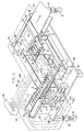
- the article-handling device shown in Fig. 1 includes an entrance section 13, an article transfer section 14, an article-reversing section 15 and an exit section 16.
- the article-handling device is supported on a frame 20 which includes a base plate 17 mounted on a plurality of legs 18, the lower ends of which legs have floor-engaging wheels 19, such as is illustrated in Figure 2. It is preferable that the wheels be of the castering variety to facilitate easy manipulation of the frame 20 from one location to another and lockable to fix the location of the frame 20 relative to other structure.
- the entrance section 13 includes a platform 21 supported on a pedestal 22 mounted on the upper surface of the base plate 17.
- a pair of laterally-spaced upstanding guide rails 23 and 24 are provided on the upper surface of the platform 21.
- the guide rail 24 is fixedly secured relative to the platform 21 whereas the guide rail 23 is anchored to the upper surface of the platform 21 at one end thereof as by an upstanding post 26 which is fixedly secured to both the platform 21 and the adjacent end 27 of the guide rail 23.
- the end 28 of the guide rail 23 remote from the end 27 is movable back and forth in a direction corresponding with the direction of the arrow Al.
- a reciprocal actuator 29 is mounted to the upper surface of the base frame 17, an upstanding rod 31 thereof being fastened to the guide rail 23 adjacent the end 28 thereof so that reciprocal movement of the actuator 29 will cause a corresponding movement of the rod 31 and end 28 of the guide rail 23 along a path defined by the arrow Al. That is, the upstanding rod 31 will move while in the upright position lengthwise of the actuator 29 in a direction generally parallel with the pathway defined by the arrow A1.
- Articles that are to be manipulated by the article handling device 10 enter the entrance section 11 and travel between the guide rails 23 and 24 and in the general direction indicated by the arrow A2.
- the article shuttling or transfer section 12 includes several platforms 32, 33 and 34 that are coplanar with each other. Each of the platforms 32, 33 and 34 are spaced from the top of the base frame 17 by leg structures as at 36, 37 and 38.
- the platform surfaces 32 and 33 have a gap 39 therebetween, the leftmost end of the gap 39 being open whereas the rightmost end of the gap 39 terminates in an enlarged rectangular opening 41.
- An elongated reciprocal actuator 42 is mounted on the upper surface of the base plate 17 and so that a portion of the left end (Figure 1) is exposed and the right end extends beneath the platform surfaces 32 and 33 and particularly is centered under the gap 39 and opening 41.
- the reciprocal actuator 42 includes a carriage 43 thereon that, upon actuation of the actuator 42, is moved lengthwise of the actuator beneath the surfaces of the platforms 32 and 33.
- the carriage 43 has an upstanding post mechanism 44 pivotally secured thereto for movement about a generally horizontally extending axle 46 ( Figure 10).
- An elongated rod 47 is connected adjacent the upper end of the post 44, the longitudinal axis of the rod extending generally parallel with the pathway represented by the arrow A2.
- the leftmost surface 48 of the rod 47 is coplanar with the leftmost surface 49 of the upstanding post 44, it being recognized that the aforesaid leftmost surfaces 48, 49 are on the right side of the post 44 and rod 47 illustrated in Figure 1.
- the width of the opening 41 is slightly greater than the dimension of the elongated rod 47 mounted on the upstanding post 44 so as to easily facilitate the aforementioned movements. It will be readily apparent to those skilled in the art that the elongated rod 47 will move from the position P1 illustrated in Figure 10 to the position P2 while being oriented above the plane of the platform surfaces 32 and 33.
- An adjustable stop 54 is provided in the transfer section 14 and is adjustably positioned on the platform surface 34.
- Parallel elongated slots 56 are provided on the stop 54 to facilitate a movement of the stop relative to the platform surface 34 in a direction generally parallel with the pathway defined by the arrow A2.
- a proximity sensor 57 is mounted on the stop 54 and is movable therewith,and is adapted to detect the presence of articles that are to be transferred in the transfer section.
- the adjustable feature embodied within the stop 54 enables the article handling device to accommodate articles of differing size.
- Fasteners 55 facilitate a locking of the stop 54 to the platform surface 34.
- the transfer section 14 includes a further elongated reciprocal actuator 58 mounted on the upper surface of the base plate 17 and extending generally parallel with the actuator 42.
- the reciprocal actuator 58 includes a carriage 59 adapted for movement lengthwise of the actuator.
- the carriage 59 also includes an upstanding post 61, however, the upstanding post 61 is fixed to the carriage 59.
- An elongated rod 62 is fastened to the upstanding post 61 adjacent the upper end thereof.
- the actuator 58 is oriented to one side of the supporting leg 38 for the platform surface 34.
- the rod 62 is of a sufficient length to extend from the upstanding post 61 to a position adjacent the leftmost edge of the stop 54 as illustrated in Figure 2.
- a further horizontally-extending post 63 is connected to the carriage 59 and extends rightwardly therefrom.
- the rightmost end of the post 63 has a laterally-extending rod 64 secured thereto, which rod extends through an elongated slot 66 provided in the supporting leg 38 and is generally parallel to the rods 62 and 47 but oriented below a plane containing the rods 62 and 47.
- the longitudinal axis of the slot 66 is parallel to the plane of the platform surfaces 32, 33 and 34.
- the article-reversing section 15 includes a generally S-shaped housing 67 which, in this particular embodiment, includes three spaced and parallel plates 71, 72 and 73, the plates 71 and 72 being connected to each other along one edge 74 by a wall section 76. Similarly, the plates 72 and 73 are connected to each other along an edge 77 by a wall section 78.
- the wall sections 76 and 78 extend parallel to one another, but are oriented on opposite sides of the housing 67 as illustrated in Figure 1.
- the S-shaped housing 67 is supported for rotational movement on a distal end of an elongated axle 79 supported on bearing structures mounted on the upper surface of the base plate 17, but are not illustrated.
- the axle 79 is rotationally driven by a rotational actuator 81 mounted on the base plate 17.
- the actuator 81 is specifically adapted to rotate the housing 67 through 180° intervals, an initial position of the housing 67 being illustrated in Figure 1.
- the axle 79 extends beneath the platform surface 34 and beneath the rod 64 extending through the elongated slot 66.
- a horizontal plane extending through the longitudinal axis of the rod 64 extends midway between the planes containing the plates 72 and 73.
- the rightmost end of the slot 66 in the supporting leg 38 opens outwardly into the spacing between the plates 72 and 73 as illustrated in Figure 2.
- the upwardly-facing surface of the plate 72 is coplanar with the platform surfaces 32, 33 and 34 when the housing 67 is in its initial position illustrated in Figure 1.
- the stroke of the actuator 58 is shorter than is the stroke of the actuator 42, the rod 62 moving rightwardly and stopping shortly before the housing 67 whereas the rod 47 moves all the way to the opening 41 in the platform surfaces 32 and 33.
- a stop mechanism 82 is provided for limiting the degree of rotation of the housing 67 to the aforesaid 180°. More specifically, the stop mechanism 82 includes an actuator 83 adapted to reciprocate an elongated rod 84 lengthwise of its longitudinal axis to cause a shoe 86 to be moved toward and away from the housing 67, the shoe 86 having a leg 87 extending beneath the plate 72 to limit clockwise rotation of the housing 67 as illustrated in Figure 1.
- the actuator 83 is actuated to draw the shoe 86 and leg 87 thereof leftwardly to enable the actuator 81 to rotate the housing in a clockwise manner.
- the actuator 83 is again actuated to cause the shoe 86 and leg 87 to move to the right to engage the plate 72 to halt further movement of the housing 67 and to assure a parallel alignment of the upper surface of the plate 72 with the platform surfaces 32, 33 and 34.
- the exit section 16 includes a platform surface 88 which, in this particular embodiment, is the right most portion of the platform surfaces 32 and 33.
- the exit section 16 includes a further platform surface 89 having an upwardly-facing surface, when in the initial position thereof illustrated in Figure 1, that is parallel with the upwardly-facing surface of the plate 73 in the housing 67.
- the platform surface 89 is elevatable by an elevating actuator 91 mounted on the upwardly-facing surface of the base plate 17 and having a rod 92 thereof affixed to the underside of the platform 89.
- the exit section 16 also includes an exit ramp 93 having a ramp surface 94 that is coplanar with the platform surface 88 and an inclined ramp surface 96 for providing a transition between the ramp surface 94 and the upwardly-facing surface of a conveyor belt 97.
- the conveyor belt 97 is a part of an auxiliary piece of equipment not forming a part of the invention.
- an elongated actuator 98 capable of reciprocating a carriage 99 back and forth in a direction generally perpendicular to the longitudinal axes of the actuators 42 and 58.
- a rod 101 is secured to the carriage 99 and overlays, in its initial position, the platform surface 88.
- An actuation of the actuator 98 will cause the carriage 99 and the rod 101 affixed thereto to move from the position illustrated in Figure 1 to the position illustrated in Figure 5 wherein the rod overlays the exit ramp 93.
- a control device 102 illustrated in Figure 2 is utilized for sequentially controlling the actuations of the several actuators described above.
- the control device 102 controls the actuator 29 through the line 103, the actuator 42 through the line 104, the actuator 58 through the line 106, the actuator 81 through the line 107, the actuator 83 through the line 108, the actuator 91 through the line 109 and the actuator 98 through line 111.
- the proximity sensor 57 is connected to the control device through the line 112.
- Each article A or carton includes an elongated container part C which includes four sidewalls and two end walls defining a carton having a solid rectangular configuration.
- the container part C has a sidewardly extending flap F oriented so that it is coplanar with one of the sidewalls of the container part C.
- the flaps F enter the entrance section 13 of the article-handling device before the container part C.
- the width and length dimensions of the flap F in this particular carton equal the width and length dimensions of the container part C.
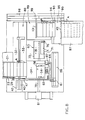
- Figure 2 illustrates the initial position of the article-handling device when articles A (individual articles are numbered 1 to 12) are present in the entrance section 13 and the flap F on the leading article 12 is located over the proximity sensor 57 and further articles A are oriented in the housing 67 between the plates 72 and 73, which articles A are inverted with respect to the articles A in the entrance section 13.
- the number of articles in the housing 67 is three.
- individual articles A will be continually fed into the entrance section 13 one at a time and at a rate that generally exceeds the rate at which articles pass through the article handling device, so that there is always assured an ample supply of articles to be processed.
- control device 102 can be adjusted so as to speed up the cycle to enable a greater number of articles to pass through the article handling device. It is, however, essential that there always be at least two articles, in the disclosed embodiment at least six articles, present in the transfer section 14 so that at least one of them can be transferred by the carriage 43 and rod 47 to the exit section 16, particularly the platform surface 88 and the remaining number transferred by the rod 62 to the spacing between the plates 71 and 72 or vice versa.
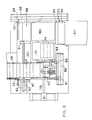
- the upstanding guide rail 23 is oriented in the solid line position illustrated in Figure 6.
- the actuator 29 is also actuated to move the upstanding guide rail to the broken line position thereof illustrated in Figure 6 to push the articles A up against the stationary guide rail 24. This serves to align the end walls of each of the articles A with each other before further processing thereof is permitted. This movement also effects a holding of the articles not to be transferred toward the exit section 16 from moving prematurely toward the stop 54. This leaves six articles in the transfer section 14 unrestrained.
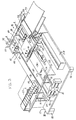
- the control device 102 causes the carriages 43 and 59 to be shifted from the Figure 2 position to the Figure 3 position to place a plurality of articles (here three) onto the platform surface 88 in the exit section 14 and a plurality of articles equalling the number of articles on the platform surface 88 into the region between the plates 71 and 72 in the housing 67. Simultaneously therewith, the rod 64 on the carriage 59 will urge three articles A that were previously in the region between the plates 72 and 73 of the housing 67 onto the platform surface 89. As explained above, the articles on the platform surface 89 are all upside down with respect to the articles A on the platform surface 88.
- the upstanding post 44 and rod 47 illustrated in Figure 3 are immediately caused to drop through the opening 41 by reason of the bracket 51 ( Figure 10) engaging the block 53 as aforesaid.
- the control device 102 then causes the actuators 29, 42 and 58 to be activated to effect a return stroke causing the upstanding rod 31 of the actuator 29 to return to its initial position illustrated in Figure 2 and both of the carriages 43 and 59 to return to their initial position also illustrated in Figure 2. Since the total stroke length of the actuator 58 is substantially shorter than the stroke length of the actuator 42, the rod 62 is returned to its initial broken line position illustrated in Figure 3 much faster than is the rod 47 returned to its initial position.
- the actuator 83 is activated to retract the shoe 86 and leg 87 from beneath the plate 72 and immediately thereafter the actuator 81 is actuated to cause the housing 67 to rotate in a clockwise direction as illustrated in Figure 4.
- the elevator actuator 91 is activated to lift the platform surface 89 vertically to bring the articles A located thereon to the same level as the articles A on the platform surface 88.
- the actuator 98 is activated to cause the carriage 99 to move forwardly from its initial position illustrated in Figure 2 toward the exit conveyor 97.
- the flaps F on the articles A that are transferred from the platform section 88 onto the platform section 89 overlap the carton portion C of the articles that were already present on the platform surface 89 and, similarly, the flaps on the articles that were previously on the platform surface 89 overlap the container portion C of the articles coming from the platform surface 88 onto the platform surface 89.
- a block of six articles are formed which define a solid rectangular form capable of being easily packaged and with no wasted space.
- the actuator 83 is sequentially activated to return the shoe 86 and leg 87 to its original position just prior to the arrival of the plate 72 at its Figure 5 position so as to effectively stop the plate 72 so that it will become aligned with the platform surface 34.
- the actuator 91 is also sequentially actuated to lower the elevatable platform 89 from the position illustrated in Figure 5 to the position illustrated in Figure 2.
- the actuator 98 is sequentially actuated for a return stroke to move the carriage 99 back to its initial position as illustrated in Figure 2.
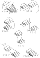
- Figure 1B shows an arrow that has been marked with the reference corresponding to the actuator 58 to schematically indicate that articles 10,11 and 12 have been moved into the housing 67.
- Articles 7, 8 and 9 are moved by the actuator 42 to the exit section 16, particularly onto the platform surface 88 ( Figure 1D).
- Figure 1C articles 10, 11 and 12 are rotated clockwise 180° in the housing 67.
- the actuators 42 and 58 will bring, respectively, articles 1, 2 and 3 onto the platform surface 88 and upside down articles 10, 11 and 12 onto the platform surface 89.
- Figure 1E schematically represents an elevation of the platform surface 89 to bring the upside down articles 10, 11 and 12 up to the same level as the articles 1, 2 and 3 on the platform surface 88.
- Figure 1F schematically represents a movement of the articles 1, 2 and 3 by the actuator 98 from the platform surface 88 onto the platform surface 89 and into united engagement with the upside down articles 10, 11 and 12 to the united grouping shown in Figure 1G, corresponding to a movement from the exit section 16 by the exit conveyor 97. Since the united grouping of articles forms a solid rectangular configuration, the united grouping of articles can be easily wrapped in a foil and packaged into a shipping carton.
- the position of the stop 54 can be adjusted on the surface 34 so as to allow more (or less) than six articles to enter the transfer section.
- the position of the stop 54 can be adjusted on the surface 34 so as to allow more (or less) than six articles to enter the transfer section.
Landscapes
- Engineering & Computer Science (AREA)
- Mechanical Engineering (AREA)
- Devices That Are Associated With Refrigeration Equipment (AREA)
- Electrical Discharge Machining, Electrochemical Machining, And Combined Machining (AREA)
- Manipulator (AREA)
- Attitude Control For Articles On Conveyors (AREA)
- Control And Other Processes For Unpacking Of Materials (AREA)
- Supplying Of Containers To The Packaging Station (AREA)
Claims (13)
- Gegenstand-Handhabungsvorrichtung zum Handhaben von identischen Gegenständen (A) mit einem Ende, das dicker ist als das andere Ende, in die Vorrichtung längs einer eine Vielzahl identisch ausgerichteter Gegenstände enthaltenden Zuführstrecke eintretend, wobei das Vorderende jedes Gegenstands jeweils gleiche Dicke aufweist, umfassend:einen Rahmen (20),eine am Rahmen befindliche Einrichtung (13) zur Festlegung einer Einlaufstrecke (A2) zum Aufnehmen eines einzigen fortlaufenden Stroms identisch ausgerichteter Gegenstände von der Zuführstrecke,am Rahmen vorgesehene, eine seitlich oder quer von der Einlaufstrecke beabstandete Austrittsstrecke festlegende Mittel (16, 88, 89, 93, 97) zum Aufnehmen eines einzigen und intermittierenden Stroms von miteinander vereinigten Paaren der Gegenstände, wobei das vorlaufende Ende eines ersten Gegenstands (10, 11, 12) relativ zum fortlaufenden Ende eines zweiten Gegenstands (1, 2, 3) in der Austrittsstrecke umgedreht worden ist,eine zwischen den Einlauf- und Austrittsstrecken befindliche Gegenstand-Wendeeinrichtung (15) zum Umdrehen bzw. Wenden des vorlaufenden Endes des ersten Gegenstands relativ zum vorlaufenden Ende der Gegenstände in der Einlaufstrecke, wobei die Gegenstand-Wendeeinrichtung einen Einlaß (34, 71, 72, 76; 34, 72, 73, 77) zum Aufnehmen eines weiteren Gegenstands (4, 5, 6) von der Einlaufstrecke und einen Auslaß (59, 71, 72, 76; 89, 71, 72, 77) für den ersten Gegenstand aufweist, dessen vorlaufendes Ende, während der erste Gegenstand den Auslaß verläßt, vom bzw. gegenüber dem vorlaufenden Ende des weiteren Gegenstands umgedreht worden ist, während der weitere Gegenstand gleichzeitig in den Einlaß eintritt, wobei die Gegenstand-Wendeeinrichtung ferner ein Gehäuseelement (67) und eine Rotier- oder Dreheinrichtung (81) zum Drehen des Gehäuseelements um eine Drehachse (79) aufweist, welches Gehäuseelement erste und zweite Kammern (71, 72, 76; 72, 73, 77) darin aufweist, wobei die erste Kammer (71, 72, 76) auf den Einlaß ausgerichtet ist, wenn die zweite Kammer (72, 73, 77) auf den Auslaß ausgerichtet ist, und umgekehrt,eine Pendeleinrichtung (14, 43; 59, 62; 59, 64) zum gleichzeitigen Herbeiführen einer Verschiebung von mindestens der zweiten und weiteren Gegenstände in seitlicher oder Quer-Richtung von der Einlaufstrecke und zumindest des ersten Gegenstands vom Auslaß der Wendeeinrichtung (15) in die Austrittsstrecke, wobei der zweite Gegenstand unmittelbar zur Austrittsstrecke gefördert wird, während der weitere Gegenstand unmittelbar zum Einlaß der Wendeeinrichtung gefördert wird, undeine Steuereinrichtung (102) zur Herbeiführung eines Umkehrens oder Wendens der vorlaufenden Endposition des weiteren Gegenstands, während erster und zweiter Gegenstand längs der Austrittsstrecke aus der Vorrichtung austreten.
- Vorrichtung nach Anspruch 1, wobei die Pendeleinrichtung (14, 43; 59, 62; 59, 64) längs einer zwischen den Einlauf- und Austrittsstrecken (A2, 93) angeordneten Pendelstrecke (42, 58) hin und her bewegbar ist, welche Pendelstrecke im wesentlichen senkrecht zur Einlaufstrecke verläuft.
- Vorrichtung nach Anspruch 2, wobei die Pendelstrecke (42, 58) im wesentlichen senkrecht zur Austrittsstrecke verläuft.
- Vorrichtung nach Anspruch 2, wobei die Pendelstrecke im wesentlichen parallel zur Drehachse (79) verläuft.
- Vorrichtung nach einem der vorangehenden Ansprüche, wobei Einlaß und Auslaß in beabstandeten und parallelen Ebenen, die parallel zur Drehachse (79) und auf gegenüberliegenden Seiten derselben verlaufen, angeordnet sind.
- Vorrichtung nach Anspruch 5, wobei die Einlaufstrecke (A2) und die Austrittsstrecke (93) in einer gemeinsamen Ebene angeordnet sind.
- Vorrichtung nach Anspruch 5 oder 6, wobei die Austrittsstrecke (16, 88, 89, 93) eine Hebereinrichtung (84) zum Verschieben des ersten Gegenstands aus der Ebene des Auslasses zur Ebene der Austrittsstrecke aufweist.
- Vorrichtung nach Anspruch 7, wobei die Austrittsstrecke (16, 88, 89, 93) eine weitere Pendeleinrichtung (98, 101) zur Herbeiführung einer Verschiebung der ersten und zweiten Gegenstände längs der Austrittsstrecke aufweist und wobei die Steuereinrichtung (102) ferner eine Bewegung oder Verschiebung der Hebereinrichtung (89) bewirkt, um den ersten Gegenstand zur (in die) Ebene der Austrittsstrecke zu bringen, bevor die weitere Pendeleinrichtung das Verschieben der ersten und zweiten Gegenstände längs der Austrittsstrecke bewirkt.
- Vorrichtung nach einem der vorangehenden Ansprüche, wobei die Pendeleinrichtung (14, 43; 59, 62; 59; 64) ein erstes Pendelelement (42) zum Verschieben des zweiten Gegenstandss von der Einlaufstrecke (A2) unmittelbar zur Austrittsstrecke (16) und ein vom ersten Pendelelement getrenntes zweites Pendelelement (59, 62) zum Verschieben des weiteren Gegenstands von der Einlaufstrecke (A2) zum und durch den Einlaß zu einer der ersten und zweiten Kammern (71, 72, 76; 72, 73, 77) der Gegenstand-Wendeeinrichtung (15) und gleichzeitig damit des ersten Gegenstands aus der anderen der ersten und zweiten Kammern zur Austrittsstrecke aufweist.
- Vorrichtung nach Anspruch 9, wobei das erste Pendelelment (43) ein erstes Gegenstand-Anlageelement (47) mit einem Breitenmaß gleich einem ersten Vielfachen eines ersten Breitenmaßes eines einzelnen Gegenstands aufweist, so daß mehrere zweite Gegenstände unmittelbar zur Austrittsstrecke (16) verschoben werden, undwobei das zweite Pendelelement (59, 62) ein zweites Gegenstand-Anlageelement (62) mit einem Breitenmaß gleich einem zweiten Vielfachen eines Breitenmaßes eines einzelnen Gegenstands aufweist, so daß mehrere weitere Gegenstände von der Einlaufstrecke (A2) zum und durch den Einlaß zu einer der ersten und zweiten Kammern (71, 72, 76; 72, 73, 77) der Gegenstand-Wendeeinrichtung (15) und gleichzeitig damit mehrere der ersten Gegenstände aus der anderen der ersten und zweiten Kammern zur Austrittsstrecke (16) verschoben werden.
- Vorrichtung nach Anspruch 10, wobei erstes und zweites Vielfaches gleich groß sind.
- Vorrichtung nach Anspruch 11, wobei jeder einzelne Gegenstand (A) ein langgestreckter Behälter (C) mit einem rechteckigen Querschnitt und einer planparallelen bzw. flachen Lasche (F), die an eine Wand des Behälters anschließt und in der gleichen Ebene damit liegt, ist, wobei ein Längen- und ein Breitenmaß der Lasche im wesentlichen einem Längen- und Breitenmaß der einen Wand gleich sind, so daß die ersten und zweiten Gegenstände auf der Austrittsstrecke eine Packung eines rechteckigen Querschnitts bilden, von denen jede Packung das Doppelte des Vielfachen eines einzigen Gegenstands darin enthält.
- Vorrichtung nach Anspruch 12, wobei das Vielfache gleich 3 ist, so daß die Packung sechs einzelne Gegenstände enthält.
Applications Claiming Priority (3)
| Application Number | Priority Date | Filing Date | Title |
|---|---|---|---|
| US28827 | 1993-03-10 | ||
| US08/028,827 US5395207A (en) | 1993-03-10 | 1993-03-10 | Article handling device |
| PCT/US1994/001203 WO1994020370A1 (en) | 1993-03-10 | 1994-02-14 | Article handling device |
Publications (2)
| Publication Number | Publication Date |
|---|---|
| EP0687237A1 EP0687237A1 (de) | 1995-12-20 |
| EP0687237B1 true EP0687237B1 (de) | 1998-05-27 |
Family
ID=21845683
Family Applications (1)
| Application Number | Title | Priority Date | Filing Date |
|---|---|---|---|
| EP94908694A Expired - Lifetime EP0687237B1 (de) | 1993-03-10 | 1994-02-14 | Vorrichtung zum konditionieren von gegenständen |
Country Status (9)
| Country | Link |
|---|---|
| US (1) | US5395207A (de) |
| EP (1) | EP0687237B1 (de) |
| JP (1) | JPH08507279A (de) |
| AT (1) | ATE166624T1 (de) |
| AU (1) | AU6169594A (de) |
| DE (1) | DE69410600T2 (de) |
| DK (1) | DK0687237T3 (de) |
| ES (1) | ES2117257T3 (de) |
| WO (1) | WO1994020370A1 (de) |
Families Citing this family (7)
| Publication number | Priority date | Publication date | Assignee | Title |
|---|---|---|---|---|
| US5822953A (en) * | 1995-12-07 | 1998-10-20 | Fuji Photo Film Co., Ltd. | Method of and system for packaging rolls of photographic film in box |
| JP3710913B2 (ja) * | 1997-05-19 | 2005-10-26 | 富士写真フイルム株式会社 | 物品の包装システム |
| DE102004036162A1 (de) * | 2004-07-26 | 2006-03-23 | Focke & Co.(Gmbh & Co. Kg) | Verfahren und Vorrichtung zum Herstellen von Packungseinheiten aus mindestens zwei Packungen |
| US7458761B2 (en) * | 2004-09-24 | 2008-12-02 | Asm Assembly Automation Ltd. | Apparatus and method for flipping electronic components |
| CN103608271A (zh) * | 2011-07-28 | 2014-02-26 | 诺登机械公司 | 物品定向机 |
| US9744683B2 (en) * | 2014-02-27 | 2017-08-29 | Ideal Products of Canada | V groove insulation machine |
| US9776807B2 (en) * | 2014-10-29 | 2017-10-03 | Alain Cerf | Changing orientation of an article on a moving conveyor |
Family Cites Families (6)
| Publication number | Priority date | Publication date | Assignee | Title |
|---|---|---|---|---|
| US2069503A (en) * | 1937-02-02 | Peyser | ||
| GB835239A (en) * | 1955-12-22 | 1960-05-18 | Brecknell Dolman & Rogers Ltd | Improvements relating to the mechanical handling of articles, such as packets of sugar and other substances |
| US3143223A (en) * | 1961-06-28 | 1964-08-04 | Emhart Mfg Co | Method and means for packing articles of tapered shape |
| US3208604A (en) * | 1963-03-11 | 1965-09-28 | Ralph E Taylor | Collecting and stacking bin |
| US4672795A (en) * | 1985-12-06 | 1987-06-16 | Scandia Packaging Machinery Co. | Method of handling fifth panel packages and assembly therefor |
| US4829863A (en) * | 1987-05-15 | 1989-05-16 | Pearne, And Lacy Machine Company | High-production inverter stacker |
-
1993
- 1993-03-10 US US08/028,827 patent/US5395207A/en not_active Expired - Fee Related
-
1994
- 1994-02-14 AU AU61695/94A patent/AU6169594A/en not_active Abandoned
- 1994-02-14 ES ES94908694T patent/ES2117257T3/es not_active Expired - Lifetime
- 1994-02-14 DK DK94908694T patent/DK0687237T3/da active
- 1994-02-14 JP JP6519978A patent/JPH08507279A/ja not_active Ceased
- 1994-02-14 EP EP94908694A patent/EP0687237B1/de not_active Expired - Lifetime
- 1994-02-14 AT AT94908694T patent/ATE166624T1/de not_active IP Right Cessation
- 1994-02-14 DE DE69410600T patent/DE69410600T2/de not_active Expired - Fee Related
- 1994-02-14 WO PCT/US1994/001203 patent/WO1994020370A1/en not_active Ceased
Also Published As
| Publication number | Publication date |
|---|---|
| US5395207A (en) | 1995-03-07 |
| ES2117257T3 (es) | 1998-08-01 |
| EP0687237A1 (de) | 1995-12-20 |
| JPH08507279A (ja) | 1996-08-06 |
| AU6169594A (en) | 1994-09-26 |
| DE69410600D1 (de) | 1998-07-02 |
| DK0687237T3 (da) | 1999-02-15 |
| ATE166624T1 (de) | 1998-06-15 |
| DE69410600T2 (de) | 1998-11-12 |
| WO1994020370A1 (en) | 1994-09-15 |
Similar Documents
| Publication | Publication Date | Title |
|---|---|---|
| US6533533B1 (en) | Article handling device and system | |
| EP0639517B1 (de) | Verpackungs- und Stapelvorrichtung mit seitlicher Stapelausrichtung | |
| US6164045A (en) | Device for packaging groups of (Individual) packages | |
| EP0242758B1 (de) | Automatische Verpackungsmaschine speziell für Säcke mit mindestens einem geflachten Rand | |
| CN101112937B (zh) | 分配物体流的装置和方法 | |
| JPH0448692B2 (de) | ||
| US11697518B2 (en) | Device used to handle articles to be packaged and method used to adapt a device for the transport of articles intended for packaging | |
| EP0687237B1 (de) | Vorrichtung zum konditionieren von gegenständen | |
| US6135705A (en) | Product stacking method and apparatus | |
| US5386677A (en) | Goods arrangement method and apparatus | |
| US7073656B2 (en) | Method and apparatus for removing holes from nested product patterns | |
| CN101370725B (zh) | 码堆机的组队方法和工作站 | |
| JP3445673B2 (ja) | 商品集積装置 | |
| JPH01162632A (ja) | 物品の積み重ね装置及び方法 | |
| US5209338A (en) | Product control apparatus | |
| JP3120178B2 (ja) | パネル材の反転移載装置 | |
| US5441381A (en) | Box stacker | |
| JP2792775B2 (ja) | カツプ容器の集積方法及び装置 | |
| JPH05193624A (ja) | カップ容器の集積方法及び装置 | |
| JPS6366723B2 (de) | ||
| JP3446470B2 (ja) | 物品段積システム | |
| US6547059B2 (en) | Conveyor row former for objects having uneven cross section widths | |
| JPH04239424A (ja) | カツプ容器の集積方法及び装置 | |
| EP4429982A1 (de) | Behältergruppierungs- und übertragungseinheit für behälterpackermaschinen | |
| JPH08282628A (ja) | 箱詰め装置 |
Legal Events
| Date | Code | Title | Description |
|---|---|---|---|
| PUAI | Public reference made under article 153(3) epc to a published international application that has entered the european phase |
Free format text: ORIGINAL CODE: 0009012 |
|
| 17P | Request for examination filed |
Effective date: 19950922 |
|
| AK | Designated contracting states |
Kind code of ref document: A1 Designated state(s): AT BE CH DE DK ES FR GB GR IE IT LI LU MC NL PT SE |
|
| 17Q | First examination report despatched |
Effective date: 19951228 |
|
| RAP1 | Party data changed (applicant data changed or rights of an application transferred) |
Owner name: PHARMACIA & UPJOHN COMPANY |
|
| GRAG | Despatch of communication of intention to grant |
Free format text: ORIGINAL CODE: EPIDOS AGRA |
|
| GRAG | Despatch of communication of intention to grant |
Free format text: ORIGINAL CODE: EPIDOS AGRA |
|
| GRAH | Despatch of communication of intention to grant a patent |
Free format text: ORIGINAL CODE: EPIDOS IGRA |
|
| GRAH | Despatch of communication of intention to grant a patent |
Free format text: ORIGINAL CODE: EPIDOS IGRA |
|
| GRAA | (expected) grant |
Free format text: ORIGINAL CODE: 0009210 |
|
| AK | Designated contracting states |
Kind code of ref document: B1 Designated state(s): AT BE CH DE DK ES FR GB GR IE IT LI LU MC NL PT SE |
|
| REF | Corresponds to: |
Ref document number: 166624 Country of ref document: AT Date of ref document: 19980615 Kind code of ref document: T |
|
| REG | Reference to a national code |
Ref country code: CH Ref legal event code: NV Representative=s name: E. BLUM & CO. PATENTANWAELTE Ref country code: CH Ref legal event code: EP |
|
| REF | Corresponds to: |
Ref document number: 69410600 Country of ref document: DE Date of ref document: 19980702 |
|
| ITF | It: translation for a ep patent filed | ||
| REG | Reference to a national code |
Ref country code: ES Ref legal event code: FG2A Ref document number: 2117257 Country of ref document: ES Kind code of ref document: T3 |
|
| ET | Fr: translation filed | ||
| REG | Reference to a national code |
Ref country code: IE Ref legal event code: FG4D |
|
| REG | Reference to a national code |
Ref country code: PT Ref legal event code: SC4A Free format text: AVAILABILITY OF NATIONAL TRANSLATION Effective date: 19980825 |
|
| REG | Reference to a national code |
Ref country code: DK Ref legal event code: T3 |
|
| PLBE | No opposition filed within time limit |
Free format text: ORIGINAL CODE: 0009261 |
|
| STAA | Information on the status of an ep patent application or granted ep patent |
Free format text: STATUS: NO OPPOSITION FILED WITHIN TIME LIMIT |
|
| 26N | No opposition filed | ||
| PGFP | Annual fee paid to national office [announced via postgrant information from national office to epo] |
Ref country code: DK Payment date: 20001211 Year of fee payment: 8 |
|
| PGFP | Annual fee paid to national office [announced via postgrant information from national office to epo] |
Ref country code: NL Payment date: 20001222 Year of fee payment: 8 |
|
| PGFP | Annual fee paid to national office [announced via postgrant information from national office to epo] |
Ref country code: GB Payment date: 20010104 Year of fee payment: 8 |
|
| PGFP | Annual fee paid to national office [announced via postgrant information from national office to epo] |
Ref country code: AT Payment date: 20010105 Year of fee payment: 8 |
|
| PGFP | Annual fee paid to national office [announced via postgrant information from national office to epo] |
Ref country code: IE Payment date: 20010112 Year of fee payment: 8 |
|
| PGFP | Annual fee paid to national office [announced via postgrant information from national office to epo] |
Ref country code: PT Payment date: 20010115 Year of fee payment: 8 |
|
| PGFP | Annual fee paid to national office [announced via postgrant information from national office to epo] |
Ref country code: LU Payment date: 20010124 Year of fee payment: 8 |
|
| PGFP | Annual fee paid to national office [announced via postgrant information from national office to epo] |
Ref country code: GR Payment date: 20010129 Year of fee payment: 8 |
|
| PGFP | Annual fee paid to national office [announced via postgrant information from national office to epo] |
Ref country code: SE Payment date: 20010201 Year of fee payment: 8 Ref country code: FR Payment date: 20010201 Year of fee payment: 8 |
|
| PGFP | Annual fee paid to national office [announced via postgrant information from national office to epo] |
Ref country code: ES Payment date: 20010216 Year of fee payment: 8 |
|
| PGFP | Annual fee paid to national office [announced via postgrant information from national office to epo] |
Ref country code: MC Payment date: 20010228 Year of fee payment: 8 Ref country code: DE Payment date: 20010228 Year of fee payment: 8 |
|
| PGFP | Annual fee paid to national office [announced via postgrant information from national office to epo] |
Ref country code: BE Payment date: 20010313 Year of fee payment: 8 |
|
| PGFP | Annual fee paid to national office [announced via postgrant information from national office to epo] |
Ref country code: CH Payment date: 20010327 Year of fee payment: 8 |
|
| REG | Reference to a national code |
Ref country code: GB Ref legal event code: IF02 |
|
| PG25 | Lapsed in a contracting state [announced via postgrant information from national office to epo] |
Ref country code: LU Free format text: LAPSE BECAUSE OF NON-PAYMENT OF DUE FEES Effective date: 20020214 Ref country code: IE Free format text: LAPSE BECAUSE OF NON-PAYMENT OF DUE FEES Effective date: 20020214 Ref country code: GB Free format text: LAPSE BECAUSE OF NON-PAYMENT OF DUE FEES Effective date: 20020214 Ref country code: AT Free format text: LAPSE BECAUSE OF NON-PAYMENT OF DUE FEES Effective date: 20020214 |
|
| PG25 | Lapsed in a contracting state [announced via postgrant information from national office to epo] |
Ref country code: SE Free format text: LAPSE BECAUSE OF NON-PAYMENT OF DUE FEES Effective date: 20020215 Ref country code: ES Free format text: LAPSE BECAUSE OF NON-PAYMENT OF DUE FEES Effective date: 20020215 |
|
| PG25 | Lapsed in a contracting state [announced via postgrant information from national office to epo] |
Ref country code: LI Free format text: LAPSE BECAUSE OF NON-PAYMENT OF DUE FEES Effective date: 20020228 Ref country code: DK Free format text: LAPSE BECAUSE OF NON-PAYMENT OF DUE FEES Effective date: 20020228 Ref country code: CH Free format text: LAPSE BECAUSE OF NON-PAYMENT OF DUE FEES Effective date: 20020228 Ref country code: BE Free format text: LAPSE BECAUSE OF NON-PAYMENT OF DUE FEES Effective date: 20020228 |
|
| BERE | Be: lapsed |
Owner name: PHARMACIA & UPJOHN CY Effective date: 20020228 |
|
| PG25 | Lapsed in a contracting state [announced via postgrant information from national office to epo] |
Ref country code: PT Free format text: LAPSE BECAUSE OF NON-PAYMENT OF DUE FEES Effective date: 20020831 |
|
| PG25 | Lapsed in a contracting state [announced via postgrant information from national office to epo] |
Ref country code: NL Free format text: LAPSE BECAUSE OF NON-PAYMENT OF DUE FEES Effective date: 20020901 Ref country code: MC Free format text: LAPSE BECAUSE OF NON-PAYMENT OF DUE FEES Effective date: 20020901 |
|
| PG25 | Lapsed in a contracting state [announced via postgrant information from national office to epo] |
Ref country code: DE Free format text: LAPSE BECAUSE OF NON-PAYMENT OF DUE FEES Effective date: 20020903 |
|
| PG25 | Lapsed in a contracting state [announced via postgrant information from national office to epo] |
Ref country code: GR Free format text: LAPSE BECAUSE OF NON-PAYMENT OF DUE FEES Effective date: 20020909 |
|
| EUG | Se: european patent has lapsed |
Ref document number: 94908694.6 |
|
| GBPC | Gb: european patent ceased through non-payment of renewal fee |
Effective date: 20020214 |
|
| REG | Reference to a national code |
Ref country code: CH Ref legal event code: PL |
|
| REG | Reference to a national code |
Ref country code: DK Ref legal event code: EBP |
|
| PG25 | Lapsed in a contracting state [announced via postgrant information from national office to epo] |
Ref country code: FR Free format text: LAPSE BECAUSE OF NON-PAYMENT OF DUE FEES Effective date: 20021031 |
|
| NLV4 | Nl: lapsed or anulled due to non-payment of the annual fee |
Effective date: 20020901 |
|
| REG | Reference to a national code |
Ref country code: PT Ref legal event code: MM4A Free format text: LAPSE DUE TO NON-PAYMENT OF FEES Effective date: 20020831 |
|
| REG | Reference to a national code |
Ref country code: FR Ref legal event code: ST |
|
| REG | Reference to a national code |
Ref country code: IE Ref legal event code: MM4A |
|
| REG | Reference to a national code |
Ref country code: ES Ref legal event code: FD2A Effective date: 20031022 |
|
| PG25 | Lapsed in a contracting state [announced via postgrant information from national office to epo] |
Ref country code: IT Free format text: LAPSE BECAUSE OF NON-PAYMENT OF DUE FEES;WARNING: LAPSES OF ITALIAN PATENTS WITH EFFECTIVE DATE BEFORE 2007 MAY HAVE OCCURRED AT ANY TIME BEFORE 2007. THE CORRECT EFFECTIVE DATE MAY BE DIFFERENT FROM THE ONE RECORDED. Effective date: 20050214 |