EP0687334B1 - Metallständer als ersatz für holzständer - Google Patents
Metallständer als ersatz für holzständer Download PDFInfo
- Publication number
- EP0687334B1 EP0687334B1 EP94903241A EP94903241A EP0687334B1 EP 0687334 B1 EP0687334 B1 EP 0687334B1 EP 94903241 A EP94903241 A EP 94903241A EP 94903241 A EP94903241 A EP 94903241A EP 0687334 B1 EP0687334 B1 EP 0687334B1
- Authority
- EP
- European Patent Office
- Prior art keywords
- studs
- metal
- wood
- stud
- plates
- Prior art date
- Legal status (The legal status is an assumption and is not a legal conclusion. Google has not performed a legal analysis and makes no representation as to the accuracy of the status listed.)
- Expired - Lifetime
Links
- 239000002184 metal Substances 0.000 title claims abstract description 36
- 239000002023 wood Substances 0.000 title claims abstract description 35
- 238000010276 construction Methods 0.000 claims abstract description 5
- 238000005192 partition Methods 0.000 claims abstract description 5
- 238000009432 framing Methods 0.000 claims abstract description 3
- 238000005452 bending Methods 0.000 claims description 2
- 238000000034 method Methods 0.000 claims 1
- 238000000638 solvent extraction Methods 0.000 abstract 1
- 229910000831 Steel Inorganic materials 0.000 description 5
- 239000000463 material Substances 0.000 description 5
- 239000010959 steel Substances 0.000 description 5
- 239000002245 particle Substances 0.000 description 3
- 238000006424 Flood reaction Methods 0.000 description 1
- 241000256602 Isoptera Species 0.000 description 1
- 241001153212 Strix occidentalis Species 0.000 description 1
- 239000004035 construction material Substances 0.000 description 1
- 238000012986 modification Methods 0.000 description 1
- 230000004048 modification Effects 0.000 description 1
- 238000007634 remodeling Methods 0.000 description 1
- 238000000926 separation method Methods 0.000 description 1
- 238000007493 shaping process Methods 0.000 description 1
- 230000035939 shock Effects 0.000 description 1
- 238000009827 uniform distribution Methods 0.000 description 1
- 230000003313 weakening effect Effects 0.000 description 1
Images
Classifications
-
- E—FIXED CONSTRUCTIONS
- E04—BUILDING
- E04B—GENERAL BUILDING CONSTRUCTIONS; WALLS, e.g. PARTITIONS; ROOFS; FLOORS; CEILINGS; INSULATION OR OTHER PROTECTION OF BUILDINGS
- E04B2/00—Walls, e.g. partitions, for buildings; Wall construction with regard to insulation; Connections specially adapted to walls
- E04B2/74—Removable non-load-bearing partitions; Partitions with a free upper edge
- E04B2/76—Removable non-load-bearing partitions; Partitions with a free upper edge with framework or posts of metal
- E04B2/78—Removable non-load-bearing partitions; Partitions with a free upper edge with framework or posts of metal characterised by special cross-section of the frame members as far as important for securing wall panels to a framework with or without the help of cover-strips
- E04B2/7854—Removable non-load-bearing partitions; Partitions with a free upper edge with framework or posts of metal characterised by special cross-section of the frame members as far as important for securing wall panels to a framework with or without the help of cover-strips of open profile
- E04B2/789—Removable non-load-bearing partitions; Partitions with a free upper edge with framework or posts of metal characterised by special cross-section of the frame members as far as important for securing wall panels to a framework with or without the help of cover-strips of open profile of substantially U- or C- section
Definitions
- the invention relates to the field of construction materials and specifically to metal studs to replace conventional vertical wood studs, such as 50,8x101,6mm (2" x 4") wood studs (nominal dimensions) used to form walls having a unique configuration on the ends of the metal studs that meets structural requirements for walls yet allows carpenters to assemble wall sections at least as conveniently and rapidly as they can using wood studs, without additional training or new tools, to form a less expensive and higher quality frame for a wall.
- conventional vertical wood studs such as 50,8x101,6mm (2" x 4"
- wood studs nominal dimensions
- Walls or sections of walls in houses, offices or other buildings have been typically constructed by use of opposing horizontal wood plates, consisting typically of 50,8x101,6mm (2" x 4") lumber, one each being adjacent to the floor and ceiling respectively, between which vertical wood studs are attached with a certain uniform separation, typically 406,4mm (16"), between each of the vertical studs, with the connection being made between the top and bottom horizontal wood plates and the vertical wood studs by means of toe nailing.
- Metal has advantages over wood as a material for vertical studs in that metal will not warp over time, will not be subject to termites and other vermin, and will consistently provide a flat surface to which material, such as drywall, forming the vertical surface of the wall may be attached, resulting in a perfectly flat wall and a metal stud is lighter than a wood stud.
- wood has been the material of choice for the use as vertical studs in substantial part because wood studs have been easier for carpenters to use in assembling sections of walls. That assembly typically occurs on the floor of the building under construction or remodeling. After assembly of a section of wall, the section is tilted or lifted into a vertical position and moved to its intended location. Prior to the invention, carpenters have been unable to use metal vertical studs because of the additional time, tools or materials required for their use in assembling wall sections.
- the invention is a metal stud having a particular configuration at each end to allow efficient connection to wood plates to be permanently positioned along the floor and along the ceiling, by a carpenter without additional training or new tools, to interconnect these metal and wood members to provide a non-weight-bearing wall frame of superior quality.
- An object of this invention is to provide a metal stud to replace the conventional wood stud, typically of 50,8x101,6mm (2" x 4") (nominal dimensions).
- Another object of this invention is to provide a metal stud that can be used by carpenters, and without the use of new tools and without any significant additional training, to assemble sections of walls or partitions in a manner similar to and at least as efficient as the manner of assembly of conventional wood studs. That typical manner of assembly is to align and connect, by nailing or stapling, the top and bottom plates to the studs, on a floor, and then to lift or tilt the assembly into its permanent position.
- Another object of this invention is to provide a metal stud that has realistic commercial utility to replace wood studs for use in assembling walls or partitions of superior quality.
- the metal stud of this invention may be made of recycled steel. It also has the additional advantage of being lighter than a wood stud.
- the objects of this invention are achieved by providing a steel stud of three walls with a [-shaped or open rectangular construction, that attaches to wood plates as easily as wood studs may be attached.
- the inventive vertical steel stud is made by conventional shaping of sheet metal generally into the form of a wood stud of conventional dimensions and having an open rectangular, [-shaped cross section and thus having two parallel side walls perpendicular to a central wall. Only one of the side walls has an extension, to form a leg or flange, of a length approximately equal to or less than the thickness (typically 50,8mm (2") nominal) of a wooden plate, on each end of that side wall. The distance between the inner surfaces of the two parallel sides is equal to the width (typically 101,6mm (4") nominal) of the top and bottom wooden plates.
- the other side wall of the metal stud has no such extension on either end, and is of a length approximately equal to the intended distance between the exposed surface of the top and bottom plates.
- a flange integral to the central portion of the stud and outwardly perpendicular thereto.
- the stud can be made by forming the sheet steel into the desired open, rectangular shape, making a cut along each seam of a length equal to or slightly less than the thickness of the top and bottom wood plates, forming a flange, on each end of the central wall portion, by bending the cut portion of such central wall outwardly and perpendicular to the surface of the central wall portion of the stud, and cutting the flange from both ends of one of the sides of the stud.
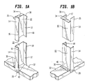
- Figures 1A and 1B are perspective views of the interconnection between a metal stud, [10], having a block-[-shaped or open, rectangular cross section, and conventional floor and ceiling wood plates, [32], wherein the end of the central section of each end is bent outwardly at the floor and ceiling plates, to form a horizontal flange [34, 36] to interface with the surface of the wood plate [32], and an extension on each end of a single side of the stud provides a nailing flange [26, 28] to the surface of the lower (floor) and upper plates.
- the metal stud is formed to have exterior dimensions generally similar to those of the conventional finished wood stud, having a depth or thickness of a nominal 50,8mm (2") and actual depth or thickness of approximately 38,1mm (11 ⁇ 2"), and a width of a nominal 101,6mm (4") and actual width of approximately 88,9mm (31 ⁇ 2"), and is made from sheet metal made from recycled steel of approximately 0.508mm (0.02 inch) in thickness.
- the stud is formed into the desired open rectangular shape having dimensions substantially equal to those of the conventional 50,8x101,6mm (2" x 4") wood stud and with the distance between the parallel side walls of the stud being substantially equal to the outside width dimensions of the 50,8x101,6mm (2 x 4), or approximately 82,55mm (31 ⁇ 4").
- the sides are approximately 25,4mm (1") in depth.
- the length of the stud is approximately 2387,6mm (94") measured between the outside of the central flanges.
- the side wall of the stud having the extensions serving as flanges on each end thus is approximately 38,1mm (11 ⁇ 2") by 2438,4mm (96"), the stud's side wall without flanges is approximately 38,1x2387,6mm (11 ⁇ 2" x 94"), and the stud's central wall is approximately 88,9x2387,6mm (31 ⁇ 2" x 94").
Landscapes
- Engineering & Computer Science (AREA)
- Architecture (AREA)
- Physics & Mathematics (AREA)
- Electromagnetism (AREA)
- Civil Engineering (AREA)
- Structural Engineering (AREA)
- Joining Of Building Structures In Genera (AREA)
- Load-Bearing And Curtain Walls (AREA)
Claims (2)
- Verbesserter Metallständer zum Ersetzen üblicher Holzständer, die als vertikale Ständer zur Bildung von Wänden oder Trennwänden in Häusern, Wohnungen, Büros oder anderen Gebäuden verwendet werden, welcher aufweist:einen rechteckigen Blechstreifen, der in [-förmige Gestalt mit einem offen rechteckigen Querschnitt zur Bildung von drei Wänden mit zwei parallelen Seitenwänden und einer Mittelwand gebogen ist; sowieeinen einstückig verbundenen und senkrecht zu jedem Ende der Mittelwand stehenden Flansch;dadurch gekennzeichnet, daß er ferner einstückig mit jedem Ende nur einer der Seitenwände verbundene Ansätze zur Bildung eines Flansches oder Schenkels an jedem der Enden aufweist.
- Verfahren zur Verwendung von Metallständern als vertikale Rahmenteile in nicht-lasttragenden Wandkonstruktionen, welches die folgenden Schritte umfaßt:Biegen von rechteckigen Blechstreifen jeweils in eine [-förmige Gestalt mit einem offen rechteckigen Querschnitt zur Bildung von drei Wänden mit zwei parallelen Seitenwänden und einer Mittelwand, um Metallständer zu bilden;Anbringen eines Flansches oder Schenkels an jedem Ende nur einer der Seitenwände;Anbringen eines Flansches am Ende jedes Endes des Mittelwandabschnitts des Ständers, der zur Mittelwand senkrecht ist;Anbringen von zwei Holzplatten;Herstellen und Markieren dieser Platten in Intervallen, um die geplante Stellung der Metallständer festzulegen;Zusammenbauen der Platten und Metallständer durch Ausrichten der Metallständer parallel zueinander und senkrecht zur den Holzplatten; undFestnageln der Metallständer an den Holzplatten.
Priority Applications (1)
| Application Number | Priority Date | Filing Date | Title |
|---|---|---|---|
| AT94903241T ATE161603T1 (de) | 1993-10-28 | 1993-10-28 | Metallständer als ersatz für holzständer |
Applications Claiming Priority (1)
| Application Number | Priority Date | Filing Date | Title |
|---|---|---|---|
| PCT/US1993/010322 WO1995012041A1 (en) | 1993-10-28 | 1993-10-28 | Metal studs to replace wood studs |
Publications (2)
| Publication Number | Publication Date |
|---|---|
| EP0687334A1 EP0687334A1 (de) | 1995-12-20 |
| EP0687334B1 true EP0687334B1 (de) | 1997-12-29 |
Family
ID=22237109
Family Applications (1)
| Application Number | Title | Priority Date | Filing Date |
|---|---|---|---|
| EP94903241A Expired - Lifetime EP0687334B1 (de) | 1993-10-28 | 1993-10-28 | Metallständer als ersatz für holzständer |
Country Status (3)
| Country | Link |
|---|---|
| EP (1) | EP0687334B1 (de) |
| DE (1) | DE69316031T2 (de) |
| WO (1) | WO1995012041A1 (de) |
Families Citing this family (3)
| Publication number | Priority date | Publication date | Assignee | Title |
|---|---|---|---|---|
| AU2016222426A1 (en) * | 2012-12-07 | 2016-11-17 | Bluescope Steel Limited | A Stud |
| USD1021151S1 (en) | 2021-04-26 | 2024-04-02 | Jaimes Industries, Inc. | Framing member |
| US20230175254A1 (en) * | 2021-12-06 | 2023-06-08 | Telling Industries, LLC | Blocking component for construction framing assembly and construction framing assembly comprising blocking component |
Family Cites Families (4)
| Publication number | Priority date | Publication date | Assignee | Title |
|---|---|---|---|---|
| US2699669A (en) * | 1948-10-28 | 1955-01-18 | United States Gypsum Co | Hollow wall construction |
| FR1342059A (fr) * | 1963-01-03 | 1963-11-02 | Cloison formée d'éléments modulaires démontables | |
| NL7104195A (de) * | 1970-04-02 | 1971-10-05 | ||
| AU4514972A (en) * | 1971-08-18 | 1974-02-07 | Matern K W | Building studs |
-
1993
- 1993-10-28 DE DE69316031T patent/DE69316031T2/de not_active Expired - Fee Related
- 1993-10-28 WO PCT/US1993/010322 patent/WO1995012041A1/en not_active Ceased
- 1993-10-28 EP EP94903241A patent/EP0687334B1/de not_active Expired - Lifetime
Also Published As
| Publication number | Publication date |
|---|---|
| EP0687334A1 (de) | 1995-12-20 |
| DE69316031D1 (de) | 1998-02-05 |
| WO1995012041A1 (en) | 1995-05-04 |
| DE69316031T2 (de) | 1998-06-10 |
Similar Documents
| Publication | Publication Date | Title |
|---|---|---|
| US5524400A (en) | Wall assembly and method of making the same | |
| US6698157B1 (en) | Structural insulated panel building system | |
| EP2240649B1 (de) | Trockenwandabstützvorrichtung | |
| US5740644A (en) | Wall with horizontal metal stud and reinforcement channel therefor | |
| CA2446005C (en) | Improved hip jackgirder connection | |
| US2200159A (en) | Construction element | |
| US5440848A (en) | Metal studs to replace wood studs | |
| CA2109676C (en) | Multiple use corner clip | |
| US5625997A (en) | Composite beam | |
| US9500023B2 (en) | Pre-fabricated structural framing kit and method | |
| EP0243134B1 (de) | Wand | |
| EP0687334B1 (de) | Metallständer als ersatz für holzständer | |
| EP0110849B1 (de) | Eine Oberfläche bildende Platte | |
| US6418682B1 (en) | Non-structural steel studs | |
| US5117602A (en) | Structural panel for pre-fabricated buildings | |
| CA1137732A (en) | Composite joists, joist assemblies and building panels including such joist assemblies | |
| EP1460195A1 (de) | Verbundträger | |
| US5022210A (en) | Construction systems and elements thereof | |
| US20050055966A1 (en) | Integrated framing system | |
| CA2180134A1 (en) | Metal studs to replace wood studs | |
| CA2088043A1 (en) | Structural system using light weight metal members | |
| US20030182890A1 (en) | Truss and joist brace | |
| CA2280506C (en) | Non-structural steel studs | |
| GB2341400A (en) | Mounting plasterboard panels | |
| JPH0523690Y2 (de) |
Legal Events
| Date | Code | Title | Description |
|---|---|---|---|
| PUAI | Public reference made under article 153(3) epc to a published international application that has entered the european phase |
Free format text: ORIGINAL CODE: 0009012 |
|
| 17P | Request for examination filed |
Effective date: 19951024 |
|
| AK | Designated contracting states |
Kind code of ref document: A1 Designated state(s): AT BE CH DE DK ES FR GB GR IE IT LI LU MC NL PT SE |
|
| RAP1 | Party data changed (applicant data changed or rights of an application transferred) |
Owner name: H. L. STUD, INC. |
|
| RIN1 | Information on inventor provided before grant (corrected) |
Inventor name: DEFFET, THOMAS |
|
| GRAG | Despatch of communication of intention to grant |
Free format text: ORIGINAL CODE: EPIDOS AGRA |
|
| 17Q | First examination report despatched |
Effective date: 19970217 |
|
| GRAH | Despatch of communication of intention to grant a patent |
Free format text: ORIGINAL CODE: EPIDOS IGRA |
|
| GRAH | Despatch of communication of intention to grant a patent |
Free format text: ORIGINAL CODE: EPIDOS IGRA |
|
| GRAA | (expected) grant |
Free format text: ORIGINAL CODE: 0009210 |
|
| AK | Designated contracting states |
Kind code of ref document: B1 Designated state(s): AT BE CH DE DK ES FR GB GR IE IT LI LU MC NL PT SE |
|
| PG25 | Lapsed in a contracting state [announced via postgrant information from national office to epo] |
Ref country code: NL Free format text: LAPSE BECAUSE OF FAILURE TO SUBMIT A TRANSLATION OF THE DESCRIPTION OR TO PAY THE FEE WITHIN THE PRESCRIBED TIME-LIMIT Effective date: 19971229 Ref country code: LI Free format text: LAPSE BECAUSE OF FAILURE TO SUBMIT A TRANSLATION OF THE DESCRIPTION OR TO PAY THE FEE WITHIN THE PRESCRIBED TIME-LIMIT Effective date: 19971229 Ref country code: GR Free format text: LAPSE BECAUSE OF FAILURE TO SUBMIT A TRANSLATION OF THE DESCRIPTION OR TO PAY THE FEE WITHIN THE PRESCRIBED TIME-LIMIT Effective date: 19971229 Ref country code: ES Free format text: THE PATENT HAS BEEN ANNULLED BY A DECISION OF A NATIONAL AUTHORITY Effective date: 19971229 Ref country code: DK Free format text: LAPSE BECAUSE OF NON-PAYMENT OF DUE FEES Effective date: 19971229 Ref country code: CH Free format text: LAPSE BECAUSE OF FAILURE TO SUBMIT A TRANSLATION OF THE DESCRIPTION OR TO PAY THE FEE WITHIN THE PRESCRIBED TIME-LIMIT Effective date: 19971229 Ref country code: BE Free format text: LAPSE BECAUSE OF FAILURE TO SUBMIT A TRANSLATION OF THE DESCRIPTION OR TO PAY THE FEE WITHIN THE PRESCRIBED TIME-LIMIT Effective date: 19971229 Ref country code: AT Free format text: LAPSE BECAUSE OF FAILURE TO SUBMIT A TRANSLATION OF THE DESCRIPTION OR TO PAY THE FEE WITHIN THE PRESCRIBED TIME-LIMIT Effective date: 19971229 |
|
| REF | Corresponds to: |
Ref document number: 161603 Country of ref document: AT Date of ref document: 19980115 Kind code of ref document: T |
|
| REG | Reference to a national code |
Ref country code: CH Ref legal event code: EP |
|
| ITF | It: translation for a ep patent filed | ||
| REF | Corresponds to: |
Ref document number: 69316031 Country of ref document: DE Date of ref document: 19980205 |
|
| ET | Fr: translation filed | ||
| PG25 | Lapsed in a contracting state [announced via postgrant information from national office to epo] |
Ref country code: SE Free format text: LAPSE BECAUSE OF FAILURE TO SUBMIT A TRANSLATION OF THE DESCRIPTION OR TO PAY THE FEE WITHIN THE PRESCRIBED TIME-LIMIT Effective date: 19980329 |
|
| PG25 | Lapsed in a contracting state [announced via postgrant information from national office to epo] |
Ref country code: PT Free format text: LAPSE BECAUSE OF FAILURE TO SUBMIT A TRANSLATION OF THE DESCRIPTION OR TO PAY THE FEE WITHIN THE PRESCRIBED TIME-LIMIT Effective date: 19980330 |
|
| NLV1 | Nl: lapsed or annulled due to failure to fulfill the requirements of art. 29p and 29m of the patents act | ||
| REG | Reference to a national code |
Ref country code: IE Ref legal event code: FG4D Free format text: 78106 |
|
| REG | Reference to a national code |
Ref country code: CH Ref legal event code: PL |
|
| PG25 | Lapsed in a contracting state [announced via postgrant information from national office to epo] |
Ref country code: LU Free format text: LAPSE BECAUSE OF NON-PAYMENT OF DUE FEES Effective date: 19981028 Ref country code: IE Free format text: LAPSE BECAUSE OF NON-PAYMENT OF DUE FEES Effective date: 19981028 |
|
| PLBE | No opposition filed within time limit |
Free format text: ORIGINAL CODE: 0009261 |
|
| STAA | Information on the status of an ep patent application or granted ep patent |
Free format text: STATUS: NO OPPOSITION FILED WITHIN TIME LIMIT |
|
| 26N | No opposition filed | ||
| PG25 | Lapsed in a contracting state [announced via postgrant information from national office to epo] |
Ref country code: MC Free format text: LAPSE BECAUSE OF NON-PAYMENT OF DUE FEES Effective date: 19990430 |
|
| REG | Reference to a national code |
Ref country code: GB Ref legal event code: IF02 |
|
| PGFP | Annual fee paid to national office [announced via postgrant information from national office to epo] |
Ref country code: FR Payment date: 20020906 Year of fee payment: 10 |
|
| PGFP | Annual fee paid to national office [announced via postgrant information from national office to epo] |
Ref country code: GB Payment date: 20020916 Year of fee payment: 10 |
|
| PGFP | Annual fee paid to national office [announced via postgrant information from national office to epo] |
Ref country code: DE Payment date: 20020924 Year of fee payment: 10 |
|
| PG25 | Lapsed in a contracting state [announced via postgrant information from national office to epo] |
Ref country code: GB Free format text: LAPSE BECAUSE OF NON-PAYMENT OF DUE FEES Effective date: 20031028 |
|
| PG25 | Lapsed in a contracting state [announced via postgrant information from national office to epo] |
Ref country code: DE Free format text: LAPSE BECAUSE OF NON-PAYMENT OF DUE FEES Effective date: 20040501 |
|
| GBPC | Gb: european patent ceased through non-payment of renewal fee |
Effective date: 20031028 |
|
| PG25 | Lapsed in a contracting state [announced via postgrant information from national office to epo] |
Ref country code: FR Free format text: LAPSE BECAUSE OF NON-PAYMENT OF DUE FEES Effective date: 20040630 |
|
| REG | Reference to a national code |
Ref country code: FR Ref legal event code: ST |
|
| PG25 | Lapsed in a contracting state [announced via postgrant information from national office to epo] |
Ref country code: IT Free format text: LAPSE BECAUSE OF NON-PAYMENT OF DUE FEES Effective date: 20051028 |