EP0687347B1 - Getriebe mit veränderbarer übersetzung - Google Patents
Getriebe mit veränderbarer übersetzung Download PDFInfo
- Publication number
- EP0687347B1 EP0687347B1 EP95906308A EP95906308A EP0687347B1 EP 0687347 B1 EP0687347 B1 EP 0687347B1 EP 95906308 A EP95906308 A EP 95906308A EP 95906308 A EP95906308 A EP 95906308A EP 0687347 B1 EP0687347 B1 EP 0687347B1
- Authority
- EP
- European Patent Office
- Prior art keywords
- pulley
- torque
- gear
- radius
- variable
- Prior art date
- Legal status (The legal status is an assumption and is not a legal conclusion. Google has not performed a legal analysis and makes no representation as to the accuracy of the status listed.)
- Expired - Lifetime
Links
- 230000007246 mechanism Effects 0.000 title claims abstract description 38
- 230000006835 compression Effects 0.000 claims description 2
- 238000007906 compression Methods 0.000 claims description 2
- 230000005540 biological transmission Effects 0.000 description 9
- 238000010586 diagram Methods 0.000 description 9
- 230000006978 adaptation Effects 0.000 description 4
- 229910000831 Steel Inorganic materials 0.000 description 3
- 239000010959 steel Substances 0.000 description 3
- 230000000694 effects Effects 0.000 description 2
- 238000004519 manufacturing process Methods 0.000 description 2
- 239000000463 material Substances 0.000 description 2
- 238000002485 combustion reaction Methods 0.000 description 1
- 230000000295 complement effect Effects 0.000 description 1
- 238000010276 construction Methods 0.000 description 1
- 238000000034 method Methods 0.000 description 1
- 238000007493 shaping process Methods 0.000 description 1
- 238000004804 winding Methods 0.000 description 1
Images


Classifications
-
- B—PERFORMING OPERATIONS; TRANSPORTING
- B62—LAND VEHICLES FOR TRAVELLING OTHERWISE THAN ON RAILS
- B62M—RIDER PROPULSION OF WHEELED VEHICLES OR SLEDGES; POWERED PROPULSION OF SLEDGES OR SINGLE-TRACK CYCLES; TRANSMISSIONS SPECIALLY ADAPTED FOR SUCH VEHICLES
- B62M9/00—Transmissions characterised by use of an endless chain, belt, or the like
- B62M9/04—Transmissions characterised by use of an endless chain, belt, or the like of changeable ratio
- B62M9/06—Transmissions characterised by use of an endless chain, belt, or the like of changeable ratio using a single chain, belt, or the like
- B62M9/08—Transmissions characterised by use of an endless chain, belt, or the like of changeable ratio using a single chain, belt, or the like involving eccentrically- mounted or elliptically-shaped driving or driven wheel; with expansible driving or driven wheel
-
- F—MECHANICAL ENGINEERING; LIGHTING; HEATING; WEAPONS; BLASTING
- F16—ENGINEERING ELEMENTS AND UNITS; GENERAL MEASURES FOR PRODUCING AND MAINTAINING EFFECTIVE FUNCTIONING OF MACHINES OR INSTALLATIONS; THERMAL INSULATION IN GENERAL
- F16H—GEARING
- F16H3/00—Toothed gearings for conveying rotary motion with variable gear ratio or for reversing rotary motion
- F16H3/02—Toothed gearings for conveying rotary motion with variable gear ratio or for reversing rotary motion without gears having orbital motion
- F16H3/42—Toothed gearings for conveying rotary motion with variable gear ratio or for reversing rotary motion without gears having orbital motion with gears having teeth formed or arranged for obtaining multiple gear ratios, e.g. nearly infinitely variable
- F16H3/426—Toothed gearings for conveying rotary motion with variable gear ratio or for reversing rotary motion without gears having orbital motion with gears having teeth formed or arranged for obtaining multiple gear ratios, e.g. nearly infinitely variable the teeth being arranged on a generally flat, e.g. disc-type surface
-
- F—MECHANICAL ENGINEERING; LIGHTING; HEATING; WEAPONS; BLASTING
- F16—ENGINEERING ELEMENTS AND UNITS; GENERAL MEASURES FOR PRODUCING AND MAINTAINING EFFECTIVE FUNCTIONING OF MACHINES OR INSTALLATIONS; THERMAL INSULATION IN GENERAL
- F16H—GEARING
- F16H55/00—Elements with teeth or friction surfaces for conveying motion; Worms, pulleys or sheaves for gearing mechanisms
- F16H55/32—Friction members
- F16H55/52—Pulleys or friction discs of adjustable construction
- F16H55/54—Pulleys or friction discs of adjustable construction of which the bearing parts are radially adjustable
-
- F—MECHANICAL ENGINEERING; LIGHTING; HEATING; WEAPONS; BLASTING
- F16—ENGINEERING ELEMENTS AND UNITS; GENERAL MEASURES FOR PRODUCING AND MAINTAINING EFFECTIVE FUNCTIONING OF MACHINES OR INSTALLATIONS; THERMAL INSULATION IN GENERAL
- F16H—GEARING
- F16H9/00—Gearings for conveying rotary motion with variable gear ratio, or for reversing rotary motion, by endless flexible members
- F16H9/02—Gearings for conveying rotary motion with variable gear ratio, or for reversing rotary motion, by endless flexible members without members having orbital motion
- F16H9/04—Gearings for conveying rotary motion with variable gear ratio, or for reversing rotary motion, by endless flexible members without members having orbital motion using belts, V-belts, or ropes
- F16H9/10—Gearings for conveying rotary motion with variable gear ratio, or for reversing rotary motion, by endless flexible members without members having orbital motion using belts, V-belts, or ropes engaging a pulley provided with radially-actuatable elements carrying the belt
-
- F—MECHANICAL ENGINEERING; LIGHTING; HEATING; WEAPONS; BLASTING
- F16—ENGINEERING ELEMENTS AND UNITS; GENERAL MEASURES FOR PRODUCING AND MAINTAINING EFFECTIVE FUNCTIONING OF MACHINES OR INSTALLATIONS; THERMAL INSULATION IN GENERAL
- F16H—GEARING
- F16H9/00—Gearings for conveying rotary motion with variable gear ratio, or for reversing rotary motion, by endless flexible members
- F16H9/02—Gearings for conveying rotary motion with variable gear ratio, or for reversing rotary motion, by endless flexible members without members having orbital motion
- F16H9/24—Gearings for conveying rotary motion with variable gear ratio, or for reversing rotary motion, by endless flexible members without members having orbital motion using chains or toothed belts, belts in the form of links; Chains or belts specially adapted to such gearing
Definitions
- the present invention relates to a variable ratio drive mechanism of a type which is suitable for use in bicycles and other energy transmission systems.
- the gear ratio is fixed.
- the gear ratio is defined as the ratio of the diameters of the chain drive pulley 2 (at pedals) and the chain sink pulley 1 (at the rear wheel), see Figure 1 (r/R).
- the largest diameter wheel of the wheels combination with multiple diameters on the left side of the Figure 1 is the energy input.
- the single diameter wheel to the right is the energy sink or load.
- This single diameter wheel could be a multiple diameter wheel arrangement (as illustrated on the left side). This would increase the available gear ratios. Such arrangements are well known from bicycles.
- An automatic, stepless gear shift device responding to the input torque would greatly simplify handling of a bicycle.
- the continuous torque to gear ratio adaptation would enable matching of the energy source characteristic (torque/rpm) to the energy load characteristic. If the adaptation curve fitted well between supply and load, then the total energy available would be transferred optimally into the linear motion.
- the above refers to a chain drive as found on bicycles.
- Hydraulic continuous torque converters are known, but their hydraulic slip is of disadvantage for continuous use due to friction and consequently lower transmission efficiency.
- variable ratio drive mechanisms Two other examples of variable ratio drive mechanisms are shown in US-A-2584477 from which the features of the preamble of claim 1 are known and BE-A-751678.
- the former shows various examples of bicycle chain drive mechanism including one with a pulley or gear in the form of a spring whose radius various with applied torque.
- the usual form of chain is used and thus the gear has teeth on its outer surface which engage the spaces between the chain links.
- BE-A-751678 discloses in accordance with the features of the preamble of claim 3 a circular gear or pulley which has a variable circumference and can therefore provide a variable gear ratio.
- the gear rim is formed of interengaging members which can be squeezed together to form a small circumference or pulled apart to form a large circumference.
- the rim is mounted on a central hub via springs.
- the proposed invention presents now a reliable, inexpensive and simple mechanical solution to form a continuous ratio shifting gear system.
- the present invention provides a cycle gear mechanism having a variable ratio drive mechanism including at least one pulley in the form of a spiral spring whose effective radius is variable in a stepless manner, and an endless torque transmitting element whereby torque is applied to or obtained from the pulley characterized in that the endless torque transmitting element is a belt or chain having protrusions thereon, and the spiral spring is a strap having recesses therein arranged to cooperate with said protrusions.
- the advantage of this arrangement is that the spiral strap with holes is relatively easy to produce when compared to a spiral strap having teeth. Moreover, teeth provided on a spiral strap would reduce the flexibility of the strap to an extent where the spiral strap may not respond adequately to increased torque, whereas a strap with holes remains fully flexible.
- the pulley could be the pedal driven gear of a bicycle chain drive mechanism, in which case torque is applied through the pedals, or the driven gear in which case torque is applied via the chain itself.
- the spring is preferably wound in the direction opposite to its direction of rotation.
- a cycle gear mechanism including at least one pulley which is mounted on an axle by means of radially extending compressible members, whereby the effective radius of the pulley is variable in a stepless manner; and a chain or belt for applying torque to or obtaining torque from the pulley; characterized in that the pulley has a stiff circular rim whereby without an applied force the pulley is eccentric with the axle, and with an applied force a compression of some of the members results while others are caused to be stretched so that the pulley is concentric with respect to the axle.
- the compressible members may comprise springs.
- the radius of the or each gear or pulley in the mechanism according to this invention may be arranged to be varied in response to applied torque.
- means may be provided for varying the effective radius of the pulley independently of applied torque.
- a guide roller may be provided to bear against the circumferential surface of the variable radius pulley. The roller may be movable towards and away from the axis of rotation of the pulley, to vary its effective radius.
- the transmission from one gear to another may be achieved through direct engagement between gears or pulleys.
- the transmission of motion from one gear to another may be through intermeshing teeth.
- the other gear or pulley may also be in the form of a spiral.
- torque is preferably applied to or obtained from the gear by means of a belt or chain.
- a mechanism according to the invention preferably includes two gears or pulleys, one driving and one driven, connected by a belt or chain.
- One or both of the gears may have a reducible radius, as described above.
- any combination of the gear types described above may be provided in a drive mechanism according to this invention.
- Rotary motion of the drive pulley 10 is transmitted to the driven pulley 11 via a chain or belt 12 supported by a tension wheel 13.
- the drive pulley 10 turns anti-clockwise in use to cause anti-clockwise motion of the driven pulley 11.
- the drive pulley 10 has the form of a spiral spring which winds clockwise from its centre (i.e. opposite to the direction of rotation in use).
- An increasing force F because the source, e.g. cyclist, delivers more power
- the arrangement shown in Figure 3 is identical to the arrangement shown in Figure 2 except that it includes an additional guide roller 14 shown bearing against the outer surface of the drive gear 10.
- the guide roller is so arranged that it can be moved manually towards or away from the centre of the drive gear 10.
- it may be rotatably and slidably mounted on a support arm extending radially from the centre of the spiral, the arm being arranged to be stationary as the gear 10 rotates.
- the position of the guide roller 14 defines the radius of the drive gear 10.
- the spiral radius can shrink or extend depending on the position of the guide roller 14.
- the position of the guide roller limits the maximum transmission ratio (r/R). Manually moving the guiding roller towards the centre of the spiral will "override" the stepless gear ratio defined by the torque or pulling force F.
- the cyclist can select an even lower gear ratio than that provided by the automatic mechanism. The cyclist has more control over the selection of gear ratio.
- the gear ratio selection could be defined by parameters delivered from an engine control for example.
- the appropriate gear could be selected automatically based on factors such as minimisation of exhaust gas, combustion characteristics and current conditions such as temperature and altitude.
- the outer surface of the spiral drive pulley 10 and/or driven pulley 11 are provided with grooves 15 to engage with corresponding protrusions 16 provided on the belt 12, as shown in Figure 4(a).
- the outer surfaces of the pulleys 10 and/or 11 could carry teeth 17 for engaging between the links 18 of a chain forming the drive belt, as shown in Figure 4(b).
- the provision of protrusions or teeth on a spiral pulley may significantly reduce the flexibility and, therefore, the effectiveness of the pulley in responding to changes of torque.
- the facing surfaces of the pulleys 10 and the drive belt 12 could simply be roughened to provide a pure friction drive.
- the "chain” could carry teeth or could comprise a row of steel balls 25 joined by a steel cord or wire 26 or other strong flexible material, as shown in Figure 4(c).
- the circumferential surfaces of the or each pulley 10,11 could be provided with holes 27 for receiving the teeth or the balls 25.
- the spiral 10 could be in the form of a steel strap provided with the holes 27 for cooperating with the protrusions on the chain provided by the balls 25.
- Figure 4(d) shows a slightly more refined version in which a groove 28 is provided to receive the cord 26 as well as holes 27 for receiving the balls.
- the spiral strap with holes 27 is relatively easy to manufacture and retains full or increased flexibility when compared to a strap without holes.
- both the load pulley 11 and the drive pulley 10 could be in the form of spiral springs so as to increase the available range of gear ratios (r1/r2). Both spirals could be provided with an adjustable guide roller as shown in Figure 3.
- the change of radius r with respect to force F can be made linear or non-linear, to fit the energy supply characteristic.
- the non-linear behaviour can easily be created by varying the thickness S of the spiral along its length.
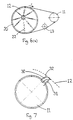
- the drive pulley 12 has a circular rim 20 connected to a central hub or axle 21 via a series of springs 22 acting as spokes for supporting the rim 20.
- the springs 22 may be compressed to shorten their length.
- the arrangement is such that without any applied force as shown in Figure 6a the rim 20 is concentric with the axle 21.
- An increasing force F causes the springs to be compressed causing the rim 20 to collapse inwardly reducing the effective radius of the pulley and hence the effective gear ratio.
- the developing force F resulting from input torque brings the balance of the springs out of centre thus reducing the torque defining radius r (which extends from the axis to the pulling point of the belt or chain).
- the rim 20 is stiff so that it retains its circular shape.
- Figure 6b shows the configuration with torque applied.
- the stiff rim 20 appears to float with respect to the axis of rotation. Some of the springs 22 are compressed to reduce the effective radius while others are caused to be stretched. Again a guide roller may be introduced for manual variation of the drive ratio as with the example of Figure 3, whether the rim 20 is stiff or flexible.
- Figure 7 shows a further alternative arrangement in which the drive pulley 11 is provided with a series of arcuate members 30 about its circumference. Only one member 30 is shown but several would be provided in practice, evenly spaced around the pulley.
- Each member 30 is pivotably attached to the pulley near to its outer surface at a point adjacent one end of the arcuate surface 32 of each member 30.
- the arcuate members are biassed radially outwardly by means of springs 31 extending from a point near the other end of the arcuate surface 32 to a point on the pulley 12 spaced from the pivot point.
- the greater the force F the more the springs 31 are compressed to reduce the effective radius of the pulley and hence the effective gear ratio.
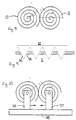
- Figure 8 shows an alternative drive mechanism in which a drive gear 10 and driven gear 11 both have the form of spiral springs and are directly engaged so that motion is transmitted from one to the other in the same way as intermeshing toothed gears. Thus, no belt or chain is needed.
- a suitable surface design is provided to ensure that the rims of the two gears would not slip against each other under applied torque.
- Figure 9 shows one possible example in which drive pulley 10 has protruding pointed teeth 34 and pulley 11 is in the form of a spiral strap having holes 35. The arrangement shown in Figure 4(a) would also be suitable.
- gears In a "beltless" arrangement the spirals should be arranged to press against each other at all times even under applied torque which tends to decrease their radii.
- the gears are mounted on respective arms 36,37 which are slidably mounted on a support frame 38 and biassed together by means not shown.
- the gear ratio could be altered automatically in response to applied torque or by some other applied force such as through one or more guide rollers as shown in Figure 3.
Landscapes
- Engineering & Computer Science (AREA)
- General Engineering & Computer Science (AREA)
- Mechanical Engineering (AREA)
- Chemical & Material Sciences (AREA)
- Combustion & Propulsion (AREA)
- Transportation (AREA)
- Transmission Devices (AREA)
- Structure Of Transmissions (AREA)
- Transmissions By Endless Flexible Members (AREA)
- Valve Device For Special Equipments (AREA)
- Vehicle Body Suspensions (AREA)
- Gears, Cams (AREA)
Claims (12)
- Zweirad-Übersetzungsmechanismus, der einen Antriebsmechanismus mit variablem Übersetzungsverhältnis besitzt, der mindestens eine Scheibe in der Form einer Spiralfeder (10, 11), deren effektiver Radius in einer stufenlosen Art und Weise variabel ist, und ein endloses, ein Drehmoment übertragendes Element, durch das ein Drehmoment auf die Scheibe aufgebracht oder von dieser erhalten wird, umfaßt, dadurch gekennzeichnet, daß das endlose, ein Drehmoment übertragende Element ein Riemen oder eine Kette (12) ist, der bzw. die Vorsprünge darauf besitzt, und daß die Spiralfeder ein Band ist, das Vertiefungen darin besitzt, die so angeordnet sind, um mit den Vorsprüngen zusammenzuwirken.
- Mechanismus nach Anspruch 1, wobei die Feder in der Richtung entgegengesetzt zu deren Drehrichtung unter Verwendung gewickelt ist.
- Zweirad-Übersetzungsmechanismus, der einen Antriebsmechanismus mit variablem Übersetzungsverhältnis besitzt, der mindestens eine Scheibe, die auf einer Achse (21) mittels sich radial erstreckender, komprimierbarer Elemente (22) befestigt ist, wodurch der effektive Radius der Scheibe in einer stufenlosen Art und Weise variabel ist, und eine Kette oder einen Riemen zum Aufbringen eines Drehmoments auf die Scheibe oder zum Erhalten eines Drehmoments von der Scheibe umfaßt, dadurch gekennzeichnet, daß die Scheibe eine steife, kreisförmige Felge besitzt, wodurch, ohne eine aufgebrachte Kraft, die Scheibe konzentrisch zu der Achse ist, und wobei mit einer aufgebrachten Kraft eine Kompression einiger der Elemente (22) folgt, während andere dazu gebracht werden, sich zu dehnen, so daß die Scheibe exzentrisch in Bezug auf die Achse (21) ist.
- Mechanismus nach Anspruch 3, wobei die komprimierbaren Elemente Federn aufweisen.
- Mechanismus nach Anspruch 3 oder 4, wobei die Scheibe in eine andere Scheibe eingreift.
- Mechanismus nach Anspruch 5, wobei die andere Scheibe dieselbe Form wie die erste, erwähnte Scheibe hat.
- Mechanismus nach einem der vorhergehenden Ansprüche, wobei der Riemen oder die Kette die Scheibe mit einer weiteren Scheibe verbindet.
- Mechanismus nach Anspruch 5, 6 oder 7, wobei der effektive Radius der weiteren Scheibe in einer stufenlosen Art und Weise variabel ist.
- Mechanismus nach einem vorhergehenden Anspruch, der Mittel zum Variieren des effektiven Radius der Scheibe unabhängig des aufgebrachten Drehmoments umfaßt.
- Mechanismus nach Anspruch 9, wobei das den Radius variierende Mittel eine Führungsrolle aufweist, die sich gegen die Umfangsoberfläche der Scheibe anlegt.
- Mechanismus nach Anspruch 10, wobei die Führungsrolle in Bezug auf die Drehachse der Scheibe bewegbar ist.
- Mechanismus nach einem vorhergehenden Anspruch, wobei der Radius der oder jeder Scheibe so ausgelegt ist, um sich in Abhängigkeit eines aufgebrachten Drehmoments zu variieren.
Applications Claiming Priority (3)
| Application Number | Priority Date | Filing Date | Title |
|---|---|---|---|
| GB9400416 | 1994-01-11 | ||
| GB9400416A GB9400416D0 (en) | 1994-01-11 | 1994-01-11 | Variable ratio drive mechanism |
| PCT/EP1995/000045 WO1995018931A2 (en) | 1994-01-11 | 1995-01-05 | Variable ratio drive mechanism |
Publications (2)
| Publication Number | Publication Date |
|---|---|
| EP0687347A1 EP0687347A1 (de) | 1995-12-20 |
| EP0687347B1 true EP0687347B1 (de) | 2000-04-19 |
Family
ID=10748632
Family Applications (1)
| Application Number | Title | Priority Date | Filing Date |
|---|---|---|---|
| EP95906308A Expired - Lifetime EP0687347B1 (de) | 1994-01-11 | 1995-01-05 | Getriebe mit veränderbarer übersetzung |
Country Status (7)
| Country | Link |
|---|---|
| US (1) | US5688199A (de) |
| EP (1) | EP0687347B1 (de) |
| JP (1) | JPH08508085A (de) |
| AT (1) | ATE191962T1 (de) |
| DE (1) | DE69516333T2 (de) |
| GB (1) | GB9400416D0 (de) |
| WO (1) | WO1995018931A2 (de) |
Families Citing this family (15)
| Publication number | Priority date | Publication date | Assignee | Title |
|---|---|---|---|---|
| US6458054B1 (en) * | 1998-07-24 | 2002-10-01 | Kenji Mimura | Transmission |
| US6432009B1 (en) | 1998-08-06 | 2002-08-13 | Brigham Young University | Continuously variable transmission |
| US6152844A (en) * | 1999-05-10 | 2000-11-28 | Daugherty; B. Eugene | Variable diameter pulley for a transmission |
| US6332852B1 (en) | 2000-05-30 | 2001-12-25 | 3561020 Canada Inc. | Variable ratio drive system |
| US7412909B2 (en) | 2002-02-07 | 2008-08-19 | Katsuya Kawakita | Non-stage transmission and device having non-stage transmission |
| AU2003207210A1 (en) * | 2002-02-07 | 2003-09-02 | Katsuya Kawakita | Continuously driving transmission, and equipment having continuously driving transmission |
| DE102007033389A1 (de) * | 2007-07-18 | 2009-01-22 | HÜBNER, Michael | Reibungsarmes stufenloses mechanisches Getriebe |
| US20110230286A1 (en) * | 2010-03-17 | 2011-09-22 | Eli Cohen | Variable Drive Transmission |
| FR2978221B1 (fr) * | 2011-07-22 | 2014-03-14 | Cyril Lilian Lucien Clopet | Mecanisme de transmission de puissance de rotation. |
| US8840127B2 (en) * | 2012-01-04 | 2014-09-23 | Robert Musgrove | Spiral cone pulley reciprocal pedal drive system and methods |
| WO2013136320A1 (en) * | 2012-03-16 | 2013-09-19 | Yayasan Putera Sampoerna | Bicycle's transmission system using less energy |
| US9371893B2 (en) * | 2013-07-22 | 2016-06-21 | Jeffrey M. Lucas | Contoured radius continuously variable transmission |
| US10239577B2 (en) * | 2013-12-19 | 2019-03-26 | J.M.J. Holdings APS | Transmission for a human powered vehicle (HPV) and such vehicle |
| CN109552545B (zh) * | 2019-01-28 | 2024-02-27 | 石甫业 | 无级变速器及其驱动方法、自行车及自行车的控制系统 |
| IL266776B (en) | 2019-05-21 | 2020-02-27 | Mizrahi Morris | A system driven by human power in a linear movement of back and forth, and uses |
Family Cites Families (14)
| Publication number | Priority date | Publication date | Assignee | Title |
|---|---|---|---|---|
| DE93896C (de) * | ||||
| DE270021C (de) * | ||||
| FR327556A (fr) * | 1902-12-20 | 1903-06-26 | Noel Andre Louis | Poulie extensible |
| FR486957A (fr) * | 1917-01-29 | 1918-05-21 | Louis-Jules Le Francois Des Courtis De La Groye | Utilisation de la force centrifuge à la variation automatique et progressive des vitesses respectives de rotation de deux organes commandés l'un par l'autre |
| DE498008C (de) * | 1926-08-23 | 1930-05-16 | Hugo Zechel | Riemscheibenwechselgetriebe |
| DE523312C (de) * | 1929-03-01 | 1931-04-22 | Gustav Steck | Geschwindigkeitswechselgetriebe mit im Durchmesser veraenderlichen UEbertragungsgliedern |
| US2584447A (en) * | 1946-09-13 | 1952-02-05 | Hayot Louis Adolphe | Variable-speed chain driving device |
| US3605512A (en) * | 1969-10-20 | 1971-09-20 | Gen Motors Corp | Expansible pulley |
| BE751678A (fr) * | 1970-06-09 | 1970-11-16 | Dalimier Serge | Poulie et variateur de vitesse comprenant au moins une telle poulie. |
| US3935751A (en) * | 1975-01-06 | 1976-02-03 | Lee Kuang Chang | Centrifugal stepless speed changing device |
| US4498351A (en) * | 1981-03-20 | 1985-02-12 | Harry B. O'Donnell, III | Continuously variable ratio transmission |
| US4516960A (en) * | 1983-06-20 | 1985-05-14 | Rahdener Maschinenfabrik August Kolbus | Variable speed chain drive |
| US4608034A (en) * | 1984-03-27 | 1986-08-26 | Reswick James B | Variable speed ratio drive |
| DE4318648C1 (de) * | 1993-06-04 | 1994-07-14 | Kraemer Hubert Dipl Ing Fh | Riementrieb mit selbttätiger stufenloser Übersetzungsänderung, insbesondere für Fahrräder |
-
1994
- 1994-01-11 GB GB9400416A patent/GB9400416D0/en active Pending
-
1995
- 1995-01-05 JP JP7518315A patent/JPH08508085A/ja not_active Ceased
- 1995-01-05 EP EP95906308A patent/EP0687347B1/de not_active Expired - Lifetime
- 1995-01-05 WO PCT/EP1995/000045 patent/WO1995018931A2/en not_active Ceased
- 1995-01-05 AT AT95906308T patent/ATE191962T1/de not_active IP Right Cessation
- 1995-01-05 DE DE69516333T patent/DE69516333T2/de not_active Expired - Fee Related
- 1995-01-25 US US08/525,605 patent/US5688199A/en not_active Expired - Fee Related
Also Published As
| Publication number | Publication date |
|---|---|
| US5688199A (en) | 1997-11-18 |
| ATE191962T1 (de) | 2000-05-15 |
| WO1995018931A3 (en) | 1995-08-17 |
| GB9400416D0 (en) | 1994-03-09 |
| EP0687347A1 (de) | 1995-12-20 |
| WO1995018931A2 (en) | 1995-07-13 |
| JPH08508085A (ja) | 1996-08-27 |
| DE69516333T2 (de) | 2000-09-21 |
| DE69516333D1 (de) | 2000-05-25 |
Similar Documents
| Publication | Publication Date | Title |
|---|---|---|
| EP0687347B1 (de) | Getriebe mit veränderbarer übersetzung | |
| US4781663A (en) | Torque responsive automatic bicycle transmission with hold system | |
| US5516132A (en) | Variable-speed transmission | |
| US20050233846A1 (en) | Variable radius continuously variable transmission | |
| US4701152A (en) | Automatic transmission for multi-speed bicycle | |
| US4373926A (en) | Automatic transmission having a continuously variable drive ratio | |
| CN100523550C (zh) | 用于跨乘式车辆的带式无级变速器和跨乘式车辆 | |
| US4713042A (en) | Automatic transmission for a bicycle | |
| US5407395A (en) | Steplessly variable belt drive for bicycle | |
| US20070213150A1 (en) | Automatic transmission for multi-speed bicycle | |
| US4741546A (en) | Torque responsive automatic bicycle transmission | |
| CN111448405A (zh) | 皮带轮和传动系统 | |
| WO2000008380A1 (en) | Continuously variable transmission | |
| US4515576A (en) | Variable speed transmission | |
| US20240149975A1 (en) | Sectioned Multiple-Step Pulley Transmission | |
| US8790199B2 (en) | Radial diaphragm spring clutch | |
| US5290206A (en) | Bar-band variable circumference adjustable-drive pulley mechanism | |
| JPH05278668A (ja) | ベルト式無段変速機構付き自転車 | |
| JP3051826U (ja) | 自転車の自動変速機構 | |
| AU2016345061A1 (en) | A transmission system | |
| WO2002022436A1 (en) | Drive system | |
| US20250050969A1 (en) | Bicycle drivetrain system, bicycle drivetrain, method, and use | |
| JPH09144824A (ja) | 無段変速機付自転車 | |
| KR20100105367A (ko) | 자동 무단 변속장치 | |
| CN1414263A (zh) | 一种传动链环及其在变速器中的应用 |
Legal Events
| Date | Code | Title | Description |
|---|---|---|---|
| PUAI | Public reference made under article 153(3) epc to a published international application that has entered the european phase |
Free format text: ORIGINAL CODE: 0009012 |
|
| ITCL | It: translation for ep claims filed |
Representative=s name: BARZANO' E ZANARDO ROMA S.P.A. |
|
| AK | Designated contracting states |
Kind code of ref document: A1 Designated state(s): AT BE CH DE DK ES FR GB GR IE IT LI LU NL PT SE |
|
| 17P | Request for examination filed |
Effective date: 19951127 |
|
| 17Q | First examination report despatched |
Effective date: 19960813 |
|
| GRAG | Despatch of communication of intention to grant |
Free format text: ORIGINAL CODE: EPIDOS AGRA |
|
| GRAG | Despatch of communication of intention to grant |
Free format text: ORIGINAL CODE: EPIDOS AGRA |
|
| GRAH | Despatch of communication of intention to grant a patent |
Free format text: ORIGINAL CODE: EPIDOS IGRA |
|
| GRAH | Despatch of communication of intention to grant a patent |
Free format text: ORIGINAL CODE: EPIDOS IGRA |
|
| GRAA | (expected) grant |
Free format text: ORIGINAL CODE: 0009210 |
|
| AK | Designated contracting states |
Kind code of ref document: B1 Designated state(s): AT BE CH DE DK ES FR GB GR IE IT LI LU NL PT SE |
|
| PG25 | Lapsed in a contracting state [announced via postgrant information from national office to epo] |
Ref country code: NL Free format text: LAPSE BECAUSE OF FAILURE TO SUBMIT A TRANSLATION OF THE DESCRIPTION OR TO PAY THE FEE WITHIN THE PRESCRIBED TIME-LIMIT Effective date: 20000419 Ref country code: IT Free format text: LAPSE BECAUSE OF FAILURE TO SUBMIT A TRANSLATION OF THE DESCRIPTION OR TO PAY THE FEE WITHIN THE PRESCRIBED TIME-LIMIT;WARNING: LAPSES OF ITALIAN PATENTS WITH EFFECTIVE DATE BEFORE 2007 MAY HAVE OCCURRED AT ANY TIME BEFORE 2007. THE CORRECT EFFECTIVE DATE MAY BE DIFFERENT FROM THE ONE RECORDED. Effective date: 20000419 Ref country code: GR Free format text: LAPSE BECAUSE OF NON-PAYMENT OF DUE FEES Effective date: 20000419 Ref country code: ES Free format text: THE PATENT HAS BEEN ANNULLED BY A DECISION OF A NATIONAL AUTHORITY Effective date: 20000419 Ref country code: BE Free format text: LAPSE BECAUSE OF FAILURE TO SUBMIT A TRANSLATION OF THE DESCRIPTION OR TO PAY THE FEE WITHIN THE PRESCRIBED TIME-LIMIT Effective date: 20000419 Ref country code: AT Free format text: LAPSE BECAUSE OF FAILURE TO SUBMIT A TRANSLATION OF THE DESCRIPTION OR TO PAY THE FEE WITHIN THE PRESCRIBED TIME-LIMIT Effective date: 20000419 |
|
| REF | Corresponds to: |
Ref document number: 191962 Country of ref document: AT Date of ref document: 20000515 Kind code of ref document: T |
|
| REG | Reference to a national code |
Ref country code: CH Ref legal event code: NV Representative=s name: KIRKER & CIE SA Ref country code: CH Ref legal event code: EP |
|
| REF | Corresponds to: |
Ref document number: 69516333 Country of ref document: DE Date of ref document: 20000525 |
|
| REG | Reference to a national code |
Ref country code: IE Ref legal event code: FG4D |
|
| PG25 | Lapsed in a contracting state [announced via postgrant information from national office to epo] |
Ref country code: SE Free format text: LAPSE BECAUSE OF FAILURE TO SUBMIT A TRANSLATION OF THE DESCRIPTION OR TO PAY THE FEE WITHIN THE PRESCRIBED TIME-LIMIT Effective date: 20000719 Ref country code: PT Free format text: LAPSE BECAUSE OF FAILURE TO SUBMIT A TRANSLATION OF THE DESCRIPTION OR TO PAY THE FEE WITHIN THE PRESCRIBED TIME-LIMIT Effective date: 20000719 Ref country code: DK Free format text: LAPSE BECAUSE OF FAILURE TO SUBMIT A TRANSLATION OF THE DESCRIPTION OR TO PAY THE FEE WITHIN THE PRESCRIBED TIME-LIMIT Effective date: 20000719 |
|
| ET | Fr: translation filed | ||
| NLV1 | Nl: lapsed or annulled due to failure to fulfill the requirements of art. 29p and 29m of the patents act | ||
| PG25 | Lapsed in a contracting state [announced via postgrant information from national office to epo] |
Ref country code: LU Free format text: LAPSE BECAUSE OF NON-PAYMENT OF DUE FEES Effective date: 20010105 Ref country code: IE Free format text: LAPSE BECAUSE OF NON-PAYMENT OF DUE FEES Effective date: 20010105 |
|
| PLBE | No opposition filed within time limit |
Free format text: ORIGINAL CODE: 0009261 |
|
| STAA | Information on the status of an ep patent application or granted ep patent |
Free format text: STATUS: NO OPPOSITION FILED WITHIN TIME LIMIT |
|
| 26N | No opposition filed | ||
| REG | Reference to a national code |
Ref country code: IE Ref legal event code: MM4A |
|
| REG | Reference to a national code |
Ref country code: GB Ref legal event code: IF02 |
|
| PGFP | Annual fee paid to national office [announced via postgrant information from national office to epo] |
Ref country code: GB Payment date: 20031231 Year of fee payment: 10 |
|
| PGFP | Annual fee paid to national office [announced via postgrant information from national office to epo] |
Ref country code: FR Payment date: 20040108 Year of fee payment: 10 |
|
| PGFP | Annual fee paid to national office [announced via postgrant information from national office to epo] |
Ref country code: DE Payment date: 20040115 Year of fee payment: 10 |
|
| PGFP | Annual fee paid to national office [announced via postgrant information from national office to epo] |
Ref country code: CH Payment date: 20040119 Year of fee payment: 10 |
|
| PG25 | Lapsed in a contracting state [announced via postgrant information from national office to epo] |
Ref country code: GB Free format text: LAPSE BECAUSE OF NON-PAYMENT OF DUE FEES Effective date: 20050105 |
|
| PG25 | Lapsed in a contracting state [announced via postgrant information from national office to epo] |
Ref country code: LI Free format text: LAPSE BECAUSE OF NON-PAYMENT OF DUE FEES Effective date: 20050131 Ref country code: CH Free format text: LAPSE BECAUSE OF NON-PAYMENT OF DUE FEES Effective date: 20050131 |
|
| PG25 | Lapsed in a contracting state [announced via postgrant information from national office to epo] |
Ref country code: DE Free format text: LAPSE BECAUSE OF NON-PAYMENT OF DUE FEES Effective date: 20050802 |
|
| GBPC | Gb: european patent ceased through non-payment of renewal fee |
Effective date: 20050105 |
|
| REG | Reference to a national code |
Ref country code: CH Ref legal event code: PL |
|
| PG25 | Lapsed in a contracting state [announced via postgrant information from national office to epo] |
Ref country code: FR Free format text: LAPSE BECAUSE OF NON-PAYMENT OF DUE FEES Effective date: 20050930 |
|
| REG | Reference to a national code |
Ref country code: FR Ref legal event code: ST |