EP0687445A2 - Détecteur ultrasonore - Google Patents
Détecteur ultrasonore Download PDFInfo
- Publication number
- EP0687445A2 EP0687445A2 EP95303245A EP95303245A EP0687445A2 EP 0687445 A2 EP0687445 A2 EP 0687445A2 EP 95303245 A EP95303245 A EP 95303245A EP 95303245 A EP95303245 A EP 95303245A EP 0687445 A2 EP0687445 A2 EP 0687445A2
- Authority
- EP
- European Patent Office
- Prior art keywords
- housing
- grooves
- acoustic
- probe
- acoustic impedance
- Prior art date
- Legal status (The legal status is an assumption and is not a legal conclusion. Google has not performed a legal analysis and makes no representation as to the accuracy of the status listed.)
- Withdrawn
Links
- 239000000523 sample Substances 0.000 title claims abstract description 109
- 239000000463 material Substances 0.000 claims abstract description 64
- 239000012530 fluid Substances 0.000 claims abstract description 31
- 230000008878 coupling Effects 0.000 claims abstract description 13
- 238000010168 coupling process Methods 0.000 claims abstract description 13
- 238000005859 coupling reaction Methods 0.000 claims abstract description 13
- 210000001519 tissue Anatomy 0.000 description 22
- 229920002972 Acrylic fiber Polymers 0.000 description 13
- 238000003384 imaging method Methods 0.000 description 7
- 210000004204 blood vessel Anatomy 0.000 description 6
- 230000009286 beneficial effect Effects 0.000 description 5
- 229920002379 silicone rubber Polymers 0.000 description 4
- 239000004945 silicone rubber Substances 0.000 description 4
- 210000001367 artery Anatomy 0.000 description 3
- 239000000919 ceramic Substances 0.000 description 3
- 238000002059 diagnostic imaging Methods 0.000 description 3
- 238000004519 manufacturing process Methods 0.000 description 3
- 238000000034 method Methods 0.000 description 3
- 230000003292 diminished effect Effects 0.000 description 2
- 210000003754 fetus Anatomy 0.000 description 2
- 239000000945 filler Substances 0.000 description 2
- 210000005003 heart tissue Anatomy 0.000 description 2
- 238000001746 injection moulding Methods 0.000 description 2
- 239000011159 matrix material Substances 0.000 description 2
- 239000004033 plastic Substances 0.000 description 2
- 229920003023 plastic Polymers 0.000 description 2
- 230000002123 temporal effect Effects 0.000 description 2
- XLYOFNOQVPJJNP-UHFFFAOYSA-N water Substances O XLYOFNOQVPJJNP-UHFFFAOYSA-N 0.000 description 2
- 239000004677 Nylon Substances 0.000 description 1
- 239000004698 Polyethylene Substances 0.000 description 1
- 210000001015 abdomen Anatomy 0.000 description 1
- 230000003187 abdominal effect Effects 0.000 description 1
- 239000000853 adhesive Substances 0.000 description 1
- 230000001070 adhesive effect Effects 0.000 description 1
- 210000003484 anatomy Anatomy 0.000 description 1
- 210000001124 body fluid Anatomy 0.000 description 1
- 238000005266 casting Methods 0.000 description 1
- 229910010293 ceramic material Inorganic materials 0.000 description 1
- 230000003247 decreasing effect Effects 0.000 description 1
- 230000000694 effects Effects 0.000 description 1
- 230000003993 interaction Effects 0.000 description 1
- 239000007788 liquid Substances 0.000 description 1
- 229920001778 nylon Polymers 0.000 description 1
- -1 polyethylene Polymers 0.000 description 1
- 229920000573 polyethylene Polymers 0.000 description 1
- 238000003825 pressing Methods 0.000 description 1
- 230000035945 sensitivity Effects 0.000 description 1
- 238000003466 welding Methods 0.000 description 1
Images


Classifications
-
- A—HUMAN NECESSITIES
- A61—MEDICAL OR VETERINARY SCIENCE; HYGIENE
- A61B—DIAGNOSIS; SURGERY; IDENTIFICATION
- A61B8/00—Diagnosis using ultrasonic, sonic or infrasonic waves
- A61B8/12—Diagnosis using ultrasonic, sonic or infrasonic waves in body cavities or body tracts, e.g. by using catheters
-
- A—HUMAN NECESSITIES
- A61—MEDICAL OR VETERINARY SCIENCE; HYGIENE
- A61B—DIAGNOSIS; SURGERY; IDENTIFICATION
- A61B8/00—Diagnosis using ultrasonic, sonic or infrasonic waves
- A61B8/44—Constructional features of the ultrasonic, sonic or infrasonic diagnostic device
- A61B8/4444—Constructional features of the ultrasonic, sonic or infrasonic diagnostic device related to the probe
- A61B8/4461—Features of the scanning mechanism, e.g. for moving the transducer within the housing of the probe
-
- G—PHYSICS
- G10—MUSICAL INSTRUMENTS; ACOUSTICS
- G10K—SOUND-PRODUCING DEVICES; METHODS OR DEVICES FOR PROTECTING AGAINST, OR FOR DAMPING, NOISE OR OTHER ACOUSTIC WAVES IN GENERAL; ACOUSTICS NOT OTHERWISE PROVIDED FOR
- G10K11/00—Methods or devices for transmitting, conducting or directing sound in general; Methods or devices for protecting against, or for damping, noise or other acoustic waves in general
- G10K11/02—Mechanical acoustic impedances; Impedance matching, e.g. by horns; Acoustic resonators
-
- A—HUMAN NECESSITIES
- A61—MEDICAL OR VETERINARY SCIENCE; HYGIENE
- A61B—DIAGNOSIS; SURGERY; IDENTIFICATION
- A61B8/00—Diagnosis using ultrasonic, sonic or infrasonic waves
- A61B8/44—Constructional features of the ultrasonic, sonic or infrasonic diagnostic device
- A61B8/4444—Constructional features of the ultrasonic, sonic or infrasonic diagnostic device related to the probe
- A61B8/445—Details of catheter construction
Definitions
- the invention generally relates to an ultrasonic probe for use, for example, in ultrasonic medical imaging systems.
- Ultrasonic probes provide a convenient and accurate way of gathering information about various structures of interest within a body being analyzed.
- the various structures of interest have acoustic impedances that are different than an acoustic impedance of a medium of the body surrounding the structures.
- such ultrasonic probes generate a signal of acoustic waves that is then acoustically coupled from the probe into the medium of the body so that the acoustic signal is transmitted into the body.
- the acoustic signal propagates through the body, part of the signal is reflected by the various structures within the body and then received by the ultrasonic probe.
- a spaced relation of the various structures within the body and qualities related to the acoustic impedance of the structures can be extrapolated from the reflected signal.
- medical ultrasonic probes provide a convenient and accurate way for a physician to collect imaging data of various anatomical parts, such as heart tissue or fetal tissue structures within a body of a patient.
- the heart or fetal tissues of interest have acoustic impedances that are different than an acoustic impedance of bodily fluids surrounding the tissue structures.
- such a medical probe generates a signal of acoustic waves that is acoustically coupled from the probe into the medium of the patient's body, so that the signal is transmitted into the patient's body.
- acoustic coupling is achieved by inserting the probe into the patient's body and through the blood vessel or artery.
- the probe includes a probe housing that contains an ultrasonic transducer.
- the transducer generates a beam of acoustic signals, which are transmitted through the probe housing.
- the ultrasonic beam scans the interior of the blood vessel.
- acoustic coupling is achieved by inserting the probe into a bodily orifice.
- less invasive means are used to achieve acoustic coupling, such as pressing the front portion of the probe into contact with a surface of the abdomen of the patient.
- such probes are mechanically scanned by moving an ultrasonic transducer within the probe.
- a front portion of such a probe includes a hemispherical housing that contains a moveable ultrasonic transducer. The housing is pressed into contact with a patient's tissue during operation of the probe. A beam of acoustic signals generated by the transducer is transmitted through the housing so as to analyze the patient's tissue. A motor coupled to the transducer causes the transducer to mechanically scan back and forth, so as to sweep the beam of acoustic signals through the patient's tissue.
- portions of the signal are weakly reflected by the various tissue structures within the body and received by the ultrasonic medical probe.
- the weakly reflected acoustic waves propagate through the probe, they are electrically sensed by electrodes coupled thereto.
- imaging system components that are electrically coupled to the electrodes extrapolate an image from the weakly reflected waves to illustrate spaced relation of the various tissue structures within the patient's body and qualities related to the acoustic impedance of the tissue structures.
- the physician views the extrapolated image on a display device coupled to the imaging system.
- the acoustic signal is only weakly reflected by the tissue structures of interest, it is important to try to provide efficient acoustic coupling between the probe and the medium of the patient's body.
- efficient acoustic coupling would insure that strength of the acoustic signal generated by the probe is not excessively diminished as the signal is transmitted from the probe into the medium of the body. Additionally, such efficient acoustic coupling would insure that strength of the weakly reflected signal is not excessively diminished as the reflected signal is received by the probe from the medium of the body.
- An impediment to efficient acoustic coupling is an acoustic impedance mis-match between an acoustic impedance of a material of the probe housing and an acoustic impedance of the medium under examination by the probe.
- a material for the probe housing is acrylic plastic, which has an acoustic impedance of approximately 3.26 * 106 kilograms/meter2second, kg/m2s.
- the acoustic impedance of acrylic plastic is mis-matched with an acoustic impedance of human tissue, which has a value of approximately 1.5 * 106 kg/m2s.
- the present invention seeks to provide an improved ultrasonic probe.
- an ultrasonic probe as specified in claim 1.
- the preferred ultrasonic probe employs one or more ultrasonic transducers substantially surrounded by a fluid.
- the ultrasonic transducer is acoustically coupled to the fluid for transmitting the beam of acoustic signals therethrough.
- a housing that is acoustically coupled with the fluid substantially encloses the fluid and the transducer.
- the housing comprises a layer portion of a material contiguous with a bulk remainder portion of the material.
- an impedance matching means is integral with the housing for controlling an acoustic impedance of the layer portion of the housing.
- the preferred ultrasonic probe can efficiently couple a beam of acoustic signals between the probe and the medium by controlling an acoustic impedance of the layer so as to substantially match the acoustic impedance of the housing material with an acoustic impedance of the medium.
- shallow grooves extending only through the layer portion of the material are used to control the acoustic impedance of the layer portion of the housing. More specifically, the shallow grooves may be micro-grooves, typically extending into the respective face of each element less than 1000 microns. In general, a depth dimension of the grooves is preferably selected to be approximately a quarter of a wavelength of the acoustic signals.
- a groove volume fraction of the layer may be selected to control acoustic impedance of the layer so as to substantially provide the desired acoustic impedance match.
- each groove has a respective volume selected so that the layer substantially provides the desired acoustic impedance match between the acoustic impedance of the material of the housing and an acoustic impedance of a desired medium such as a patient's body.
- a manufacturing advantage associated with the preferred probe is that the grooves can be easily etched, cut or molded into a wide ranges of materials with a controlled groove shape. Furthermore, when the layer providing impedance matching is integral with the housing, the preferred probe can provide acoustic impedance matching without being burdened by manufacturing and reliability problems that are associated with adhesively bonding layers of dissimilar materials to a housing or with limited high frequency performance caused by any adhesive bond lines.
- Figure 1A is a cut away perspective view of a preferred embodiment of the present invention.
- Figure 1B shows a detailed cut away perspective view of figure 1A.
- Figure 2 illustrates an alternative embodiment of grooves extending through a layer of a housing of the probe.
- Figure 3 illustrates another alternative embodiment of grooves extending through the layer of the housing.
- Figure 4A is a cut away perspective view showing another preferred embodiment of probe.
- Figure 4B shows a detailed cut away perspective view of figure 4A.
- Figure 4C is a graph illustrating a comparison of internal acoustic reverberations of the embodiment shown in FIG. 1A and the embodiment shown in FIG. 4A.
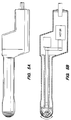
- Figure 5A shows a cut away view of yet another embodiment of probe.
- Figure 5B shows a cut away cross sectional view of FIG. 5A.
- FIG. 1A is a simplified cut away perspective view illustrating a preferred embodiment of the ultrasonic probe 100.
- the preferred embodiment of the ultrasonic probe includes a probe housing 101.
- the probe housing substantially encloses a rotatable ultrasonic transducer 103 and a fluid, preferably water, that surrounds the transducer. Alternatively, a suitable oil or other liquid may be used as the fluid.
- the probe is a catheter probe for imaging inside of a blood vessel or artery.
- a front portion of the probe housing 101 is inserted into a blood vessel V.
- the housing is substantially shaped like a hollow cylinder having closed ends, however the housing may be shaped otherwise with beneficial results. It should be understood that the housing 101 is shown in cut away view in FIG. 1A to reveal how the fluid and transducer are disposed within the housing.
- the transducer generates a beam of acoustic signals 104, which are transmitted through the fluid that surrounds the transducer and through the probe housing.
- the ultrasonic beam 104 scans the tissue of the interior of the blood vessel V.
- the ultrasonic transducer includes a body of piezoelectric ceramic material having a bulk acoustic resonant frequency that determines the frequency of the acoustic signals.
- a pair of electrodes is disposed on opposing sides of the piezoelectric body for applying a voltage that generates the acoustic signals within the piezoelectric ceramic.
- the electrodes sense a voltage produced by reflected acoustic signals received by the piezoelectric ceramic.
- the electrodes are coupled to imaging system components for extrapolating an image of the tissue from acoustic signals reflected by the tissue.
- the housing comprises a layer portion 102 of a material contiguous with a bulk remainder portion of the material.
- the material of the housing has a bulk acoustic impedance, Z HOUSING .
- Shallow grooves extend through the layer. In the preferred embodiment, the grooves substantially encircle a circumference of the probe housing.
- FIG. 1B shows a detailed cut away perspective view of the probe of FIG. 1A.
- the layer has a layer thickness defined by a depth dimension, D, of the shallow grooves extending through the layer.
- the bulk remainder portion of the material has a bulk remainder dimension, R.
- the probe housing is held in a specially contoured enclosure made of an acrylic plastic material. It should be understood that although plastic is preferred, other materials known to those skilled in the art, such as nylon, may be alternatively employed with beneficial results.
- the housing is made by injection molding.
- the acrylic plastic is injected into a suitable mold having desired groove contours.
- the acrylic plastic is first cast in the mold as a sheet having the grooves.
- the sheet is removed from the mold and rolled into a hollow cylindrical shape so that two ends of the sheet meet at a seam extending along a longitudinal dimension of the cylinder.
- the seam is then sealed using ultrasonic welding.
- additional members are welded to the cylinder as needed to complete the housing.
- the plastic may be cast as a cylinder having the grooves or as some other shape having the grooves.
- the grooves may be made using alternative methods.
- the grooves are alternatively cut into the material of the housing using a laser beam.
- the material of the housing is suitably masked and the grooves etched into the material of the housing using an etchant.
- the grooves substantially encircle the circumference of the housing
- the grooves are differently arranged.
- the grooves are substantially straight, extending along a longitudinal dimension of the housing.
- the housing is preferably made by extruding melted acrylic plastic in a tube shape through a die nozzle.
- the die nozzle is shaped so as to impress the straight grooves onto the housing as the longitudinal dimension of the housing is extruded through the nozzle.
- the layer 102 substantially provides an acoustic impedance match between the bulk acoustic impedance of the housing material and the acoustic impedance of a desired medium under examination.
- the layer substantially provides an acoustic impedance match between the bulk acoustic impedance of the housing material and the acoustic impedance of a medium such as tissue of a patient's body under examination by the probe.
- the layer 102 includes the grooves 105. In the preferred embodiment, the grooves are substantially circular and arranged approximately parallel to one another across a longitudinal dimension of the housing.
- a conformal material preferably silicone rubber, is disposed within the grooves.
- a suitable alternative conformal material for example polyethylene, may be used instead of silicone rubber.
- the selected conformal material has an acoustic impedance, Z conformal , associated therewith.
- the acoustic signals propagate through the tissue of the patient's body, portions of the signal are weakly reflected by the tissue structures within the body, are received by the ultrasonic transducer and are electrically sensed by the pair of electrodes coupled to the ultrasonic transducer.
- the reflected acoustic signals are first received by the layer portion of the housing material and then propagate through the remainder portion of the housing material. Accordingly, the acoustic signals propagate through the layer with a first velocity, and then propagate through the bulk remainder portion with a second velocity.
- the depth dimension, D, of the grooves of the layer be selected to be a quarter of a wavelength of the acoustic signals traveling through the layer with the grooves.
- the depth dimension, D, of the grooves defines thickness of the layer.
- the depth dimension, D, of each groove and a pitch dimension, P, of the respective grooves are selected to separate lateral and shear resonance modes of the layer from undesired interaction with the longitudinal resonance mode of the housing.
- the depth and pitch of the grooves are selected to provide efficient transfer of acoustic energy through the layer.
- the depth and pitch of the grooves are selected so that the layer appears homogenous to acoustic waves. In general, beneficial results are produced by a pitch to depth ratio, P/D, of less than or equal to approximately 0.4.
- Acoustic impedance of the layer is controlled so as to substantially provide an acoustic impedance match between the bulk acoustic impedance of the housing material and an acoustic impedance of the medium under examination by the probe. Accordingly, the layer provides for efficient acoustic coupling between the probe and the medium under examination.
- the acoustic impedance of the layer is substantially determined by a groove volume fraction of the layer. The groove volume fraction is based upon the width and pitch dimensions of the grooves 105.
- Z tissue is 1.5 * 106 kilograms/meter2second, kg/m2s
- the bulk acoustic impedance of acrylic plastic material of the housing, Z HOUSING is 3.26 * 106 kg/m2s
- the desired acoustic impedance of the layer, Z layer is calculated to be approximately 2.21 * 106 kg/m2s.
- the acoustic impedance of the layer is substantially controlled by the groove volume fraction of the layer. Another relevant factor is an acoustic impedance of the conformal material disposed in the grooves.
- the groove volume fraction of the layer is defined by dividing a volume of a groove extending through the layer by a sum of the volume of the groove and a volume of remaining layer material adjacent to the groove.
- a desired groove volume fraction, v is calculated from the desired acoustic impedance of the layer and respective acoustic impedances of the acrylic plastic, and the conformal material.
- the desired volume fraction, v, of the groove is approximately equal to an expression: (Z HOUSING - Z layer )/(Z HOUSING - Z conformal )
- Z HOUSING - Z conformal the conformal material having an acoustic impedance, Z conformal , of 1.5 * 106 kg/m2s, and given values for the acoustic impedance of the layer, Z layer , and the acoustic impedance of the acrylic plastic material of the housing, Z HOUSING , as articulated previously herein
- the desired groove volume fraction of the layer, v is approximately 59.6%.
- a volume fraction of the layer of the housing complements the groove volume fraction. Accordingly, for this example, the volume fraction of the layer is approximately 40.4%.
- speed of sound in the layer with the grooves, C layer can be estimated as being approximately 1900 meters/second.
- a desired frequency, f, of the acoustic signals is 2 megahertz, MHz
- the depth of the grooves, D is approximately 237.5 microns. Accordingly, the grooves are shown to be micro-grooves, extending into the layer less than 1000 microns.
- a pitch, P, of the grooves is calculated so that the pitch is less than 0.4 of the depth of the grooves: P ⁇ (0.4 * D)
- pitch of the grooves should be less than or equal to 95 microns.
- a desired value for the correction factor, k is selected based on connectivity of the acrylic plastic of the layer and the conformal material.
- the layer has 2-2 connectivity and the correction factor, k, is simply 1.
- the grooves are alternately arranged so that the layer has a different connectivity, yielding a different correction factor.
- the grooves are arranged so that the layer has a 1-3 connectivity, yielding a different correction factor of 1.25.
- the width, W, of the grooves is approximately 56.6 microns.
- the bulk remainder portion of the material has a bulk remainder dimension, R, that is substantially greater than the depth of the microgrooves.
- R the bulk remainder dimension
- relevant groove dimensions and the bulk remainder dimension are scaled accordingly.
- relevant groove dimensions of the 2 MHz probe example discussed previously are scaled by a factor of 10. Therefore, for a piezoelectric transducer each having a bulk resonant frequency of 20 MHz and respective piezoelectric layers with grooves arranged for 2-2 connectivity, relevant dimensions of the grooves are scaled down by 10 so as to have pitch of 9.5 microns, width of 5.7 microns, and depth of approximately 23.7 microns. Accordingly, the grooves are once again shown to be microgrooves, extending into the front face of the element less than 1000 microns. The bulk remainder dimension is adjusted to be approximately 700 microns.
- a number of grooves encircling the circumference of the housing and disposed along the longitudinal dimension of the housing is related to the pitch of the grooves and the longitudinal dimension of the housing.
- the number of circular grooves disposed along the longitudinal dimension of the housing is approximately between the range of 50 and 200 grooves to produce beneficial impedance matching results.
- a preferred respective number of grooves disposed along the longitudinal dimension is approximately 100 grooves. For the sake of simplicity, fewer grooves than 100 grooves are shown in FIGS. 1A and 1B.
- Figure 2 illustrates an alternative embodiment of grooves extending through a layer of the housing.
- FIG. 2 shows grooves extending through the layer, and a bulk remainder portion of the housing material.
- the grooves of FIG. 2 include a first set of grooves, a second set of grooves, and third set of grooves arranged adjacent one another. As shown, the grooves are arranged so that the grooves have a pitch, P, and a width, W.
- Each member of the first set of grooves has a respective depth, D, which is approximately equal to an integral multiple of one quarter of a first wavelength of the acoustic signals.
- each member of the second set of grooves has a respective depth dimension, D', which is approximately equal to an integral multiple of one quarter of a second wavelength of the acoustic signals.
- Each member of a third set of grooves has a respective depth dimension, D'', which is approximately equal to an integral multiple of one quarter of a third wavelength of the acoustic signals.
- Respective members of the first, second and third set of grooves are arranged in a "stair step" pattern as shown in FIG. 2.
- a single conformal filler material can be deposited in each set of grooves.
- a different conformal filler material can be deposited in each set of grooves to achieve the desired frequency response.
- the housing of the alternative embodiment is made using injection molding.
- Figure 3 illustrates another alternative embodiment of grooves extending through the layer of the housing.
- a smoothed groove profile is created, in place of the abrupt "stair step” pattern, to provide the layer with enhanced acoustic performance such as broad frequency response or improved acoustic sensitivity.
- such alternative embodiments include grooves each having a smoothed "V" profile and extending through the layer.
- Such alternative embodiments are made in a similar manner as discussed previously. As shown, the grooves are created so that the grooves have desired pitch, P, and width, W, and depth, D. In yet additional alternative embodiments, depth of the grooves is varied along the longitudinal dimension of the housing to provide further enhanced frequency response characteristics.
- FIG. 4A is a simplified cut away perspective view illustrating another preferred embodiment of the ultrasonic probe.
- the probe housing substantially encloses a rotatable ultrasonic transducer and a fluid as shown in FIG. 4A.
- the housing is substantially shaped like a hollow cylinder having closed ends, however the housing may be shaped otherwise with beneficial results. It should be understood that the housing is shown in cut away view in FIG. 4A to reveal how the fluid and transducer are disposed with the housing.
- the transducer generates a beam of acoustic signals which are transmitted through the fluid that surrounds the transducer and through the probe housing to analyze a media such as human tissue adjacent to the probe.
- the probe housing is made of a material that has an acoustic impedance.
- the probe is preferably made of an acrylic plastic, which has an acoustic impedance of approximately 3.26 * 106 kilograms/meter2second, kg/m2s.
- Disposed within the housing is the fluid, which has a different acoustic impedance than that of the housing material.
- the fluid disposed within the housing is water, which has an acoustic impedance similar to that of human tissue, approximately 1.5 * 106 kg/m2s.
- the acoustic impedance of material of the housing is mis-matched with the acoustic impedance of the fluid and is also mis-matched with the acoustic impedance of the medium under examination by the probe, such as human tissue.
- the preferred probes substantially provide impedance matching of the acoustic impedance of the housing with the acoustic impedance of the fluid so as to decrease reverberation of the acoustic signals within the probe housing.
- the housing comprises an inner layer portion of the housing material contiguous with a bulk remainder portion of the housing material. Shallow grooves extending through the inner layer portion of the housing material control the impedance of the inner layer so as to substantially provide the desired impedance match between the acoustic impedance of the housing and the acoustic impedance of the fluid.
- the described probes provide substantial impedance matching of the acoustic impedance of the housing with the acoustic impedance of a media such as human tissue under examination by the probe.
- the housing further comprises an outer layer portion of the housing material contiguous with the bulk remainder portion of the housing material. Shallow grooves extending through the inner layer portion of the housing material control the impedance of the inner layer to substantially provide the desired impedance match between the acoustic impedance of the housing and the acoustic impedance of the media under examination by the probe.
- FIG. 4B shows a detailed cut away perspective view of the probe of FIG. 4A.
- grooves extend a depth, D, through the inner layer of the housing. Additionally, grooves extend a depth D, through the outer layer of the housing. The depth dimensions of the grooves define thicknesses of the layers.
- the bulk remainder of the housing material has a dimension, R. Dimensions of the grooves are determined in as discussed in detail previously herein with respect to FIGS. 1A and 1B.
- the housing shown in FIGS. 4A and 4B is made by injecting a material such as acrylic plastic into a suitable mold having desired groove contours, in a similar manner as that described previously herein with respect to FIGS. 1A and 1B.
- a suitable conformal material such as silicone rubber, is disposed in the grooves.
- Figure 4C is a graph illustrating a comparison of internal acoustic reverberations of the probe shown in FIG. 1A and the probe shown in FIG. 4A.
- the graph represents rectified impulse responses of each probe, which have been simulated using a digital computer and the Laplace Transform Matrix Method as discussed in "A Matrix Technique for Analyzing the Performance of Multilayered Front Matched and Backed Piezoelectric Ceramic Transducers" by Lewis et al., Acoustic imaging, No. 8, pages 395-416 (1978).
- the graph of FIG. 4C shows decreased reverberations in the impulse response of the probe of FIG. 4A, relative to the impulse response of the probe of FIG. 1A.
- the simulated rectified impulse response of the probe of FIG. 1A is represented by a dashed line 410 in the graph of FIG. 4C.
- the simulated rectified impulse response of the probe of FIG. 4A is represented by a solid line 420 in the graph of FIG. 4C.
- the inner layer portion of the probe housing of FIG. 4A advantageously provides substantial impedance matching of the acoustic impedance of the housing with the acoustic impedance of the fluid, so as to decrease reverberation of the acoustic signals within the probe housing.
- Figure 5A shows a cut away view of another embodiment of the probe.
- the front portion of the probe includes a substantially hemispherical housing.
- the housing is pressed into contact with a patient's tissue during operation of the probe.
- Grooves extending through a layer portion of the housing substantially provide impedance matching as discussed in detail previously herein. As shown, the grooves are arranged so as to be substantially concentric.
- FIG. 5B is another view of the probe shown in FIG. 5A, cut away to reveal a mechanically scanned ultrasonic transducer substantially enclosed by the housing.
- a fluid surrounds the ultrasonic transducer so that a beam of acoustic signals generated by the transducer is transmitted through the fluid and through the housing.
- a motor is coupled to transducer so as to cause the transducer to mechanically scan back and forth through an arc as shown in FIG 5B.
- the ultrasonic probes described herein can provide efficient and controlled acoustic coupling to a desired medium under examination by the probe.
- a plurality of ultrasonic transducers may be provided in the probe.
Landscapes
- Health & Medical Sciences (AREA)
- Life Sciences & Earth Sciences (AREA)
- Engineering & Computer Science (AREA)
- Physics & Mathematics (AREA)
- Medical Informatics (AREA)
- Animal Behavior & Ethology (AREA)
- Radiology & Medical Imaging (AREA)
- Nuclear Medicine, Radiotherapy & Molecular Imaging (AREA)
- Biomedical Technology (AREA)
- Heart & Thoracic Surgery (AREA)
- Biophysics (AREA)
- Molecular Biology (AREA)
- Surgery (AREA)
- Pathology (AREA)
- General Health & Medical Sciences (AREA)
- Public Health (AREA)
- Veterinary Medicine (AREA)
- Acoustics & Sound (AREA)
- Multimedia (AREA)
- Ultra Sonic Daignosis Equipment (AREA)
- Transducers For Ultrasonic Waves (AREA)
- Investigating Or Analyzing Materials By The Use Of Ultrasonic Waves (AREA)
Applications Claiming Priority (2)
| Application Number | Priority Date | Filing Date | Title |
|---|---|---|---|
| US260391 | 1994-06-15 | ||
| US08/260,391 US5423319A (en) | 1994-06-15 | 1994-06-15 | Integrated impedance matching layer to acoustic boundary problems for clinical ultrasonic transducers |
Publications (2)
| Publication Number | Publication Date |
|---|---|
| EP0687445A2 true EP0687445A2 (fr) | 1995-12-20 |
| EP0687445A3 EP0687445A3 (fr) | 1996-12-11 |
Family
ID=22988977
Family Applications (1)
| Application Number | Title | Priority Date | Filing Date |
|---|---|---|---|
| EP95303245A Withdrawn EP0687445A3 (fr) | 1994-06-15 | 1995-05-15 | Détecteur ultrasonore |
Country Status (3)
| Country | Link |
|---|---|
| US (1) | US5423319A (fr) |
| EP (1) | EP0687445A3 (fr) |
| JP (1) | JPH07328005A (fr) |
Cited By (1)
| Publication number | Priority date | Publication date | Assignee | Title |
|---|---|---|---|---|
| DE10326078A1 (de) * | 2003-06-10 | 2005-01-05 | Fraunhofer-Gesellschaft zur Förderung der angewandten Forschung e.V. | Verfahren zur Messung der akustischen Impedanz einer Flüssigkeit |
Families Citing this family (16)
| Publication number | Priority date | Publication date | Assignee | Title |
|---|---|---|---|---|
| WO1999008330A1 (fr) * | 1997-08-05 | 1999-02-18 | Siemens Aktiengesellschaft | Actionneur piezoelectrique precontraint |
| US5984871A (en) * | 1997-08-12 | 1999-11-16 | Boston Scientific Technologies, Inc. | Ultrasound transducer with extended focus |
| US6371915B1 (en) | 1999-11-02 | 2002-04-16 | Scimed Life Systems, Inc. | One-twelfth wavelength impedence matching transformer |
| US6635054B2 (en) | 2000-07-13 | 2003-10-21 | Transurgical, Inc. | Thermal treatment methods and apparatus with focused energy application |
| WO2002005720A1 (fr) * | 2000-07-13 | 2002-01-24 | Transurgical, Inc. | Application d'energie a l'aide de lentille annulaire gonflable |
| US6763722B2 (en) | 2001-07-13 | 2004-07-20 | Transurgical, Inc. | Ultrasonic transducers |
| US7396332B2 (en) | 2002-06-10 | 2008-07-08 | Scimed Life Systems, Inc. | Transducer with multiple resonant frequencies for an imaging catheter |
| US20040082859A1 (en) | 2002-07-01 | 2004-04-29 | Alan Schaer | Method and apparatus employing ultrasound energy to treat body sphincters |
| JP2006518648A (ja) * | 2003-02-20 | 2006-08-17 | プロリズム,インコーポレイテッド | 心臓アブレーションデバイス |
| JP2006204617A (ja) * | 2005-01-28 | 2006-08-10 | Fuji Photo Film Co Ltd | 超音波プローブ |
| WO2007136566A2 (fr) | 2006-05-19 | 2007-11-29 | Prorhythm, Inc. | Dispositif d'ablation avec profil de puissance d'entrée optimisée et son procédé d'utilisation |
| US8974445B2 (en) | 2009-01-09 | 2015-03-10 | Recor Medical, Inc. | Methods and apparatus for treatment of cardiac valve insufficiency |
| CA2815220A1 (fr) * | 2010-10-22 | 2012-04-26 | Gore Enterprise Holdings, Inc. | Catheter comprenant un organe de commande en alliage a memoire de forme |
| DE102015015901B3 (de) * | 2015-11-26 | 2017-06-01 | Elmos Semiconductor Aktiengesellschaft | Schwingelement für einen Ultraschall-Transducer mit einer auf einem Translationsgitter basierenden Mehrfachresonanz |
| WO2017089609A2 (fr) | 2015-11-26 | 2017-06-01 | Elmos Semiconductor Aktiengesellschaft | Élément oscillant pour un transducteur ultrasonore à résonance multiple |
| DE102015015903B3 (de) * | 2015-11-26 | 2017-06-01 | Elmos Semiconductor Aktiengesellschaft | Schwingelement für einen Ultraschall-Transducer mit einer auf einer Rotationsperiodizität basierenden Mehrfachresonanz |
Family Cites Families (43)
| Publication number | Priority date | Publication date | Assignee | Title |
|---|---|---|---|---|
| US2716708A (en) * | 1950-11-17 | 1955-08-30 | Nat Res Dev | Apparatus for launching ultrasonic waves |
| US3387235A (en) * | 1964-06-11 | 1968-06-04 | Bell Telephone Labor Inc | Signal dispersion system |
| US3718898A (en) * | 1971-12-13 | 1973-02-27 | Us Navy | Transducer |
| US3833825A (en) * | 1973-04-11 | 1974-09-03 | Honeywell Inc | Wide-band electroacoustic transducer |
| US4097835A (en) * | 1976-09-20 | 1978-06-27 | Sri International | Dual transducer arrangement for ultrasonic imaging system |
| US4391281A (en) * | 1977-01-06 | 1983-07-05 | Sri International | Ultrasonic transducer system and method |
| US4205686A (en) * | 1977-09-09 | 1980-06-03 | Picker Corporation | Ultrasonic transducer and examination method |
| US4211948A (en) * | 1978-11-08 | 1980-07-08 | General Electric Company | Front surface matched piezoelectric ultrasonic transducer array with wide field of view |
| US4297607A (en) * | 1980-04-25 | 1981-10-27 | Panametrics, Inc. | Sealed, matched piezoelectric transducer |
| JPS56161799A (en) * | 1980-05-15 | 1981-12-12 | Matsushita Electric Ind Co Ltd | Ultrasonic wave probe |
| US4460841A (en) * | 1982-02-16 | 1984-07-17 | General Electric Company | Ultrasonic transducer shading |
| US4542653A (en) * | 1983-11-21 | 1985-09-24 | Advanced Technology Laboratories, Inc. | Apparatus and method for beamforming in an ultrasonic transducer array |
| US4722346A (en) * | 1983-12-16 | 1988-02-02 | Hewlett-Packard Company | Stand-off device with special fluid |
| JPH0660896B2 (ja) * | 1984-11-02 | 1994-08-10 | 株式会社日立製作所 | 超音波探触子 |
| DE3501808A1 (de) * | 1985-01-21 | 1986-07-24 | Siemens AG, 1000 Berlin und 8000 München | Ultraschallwandler |
| DE3678635D1 (de) * | 1985-05-20 | 1991-05-16 | Matsushita Electric Industrial Co Ltd | Ultraschallwandler. |
| US4888861A (en) * | 1985-10-10 | 1989-12-26 | The United States Of America As Represented By The United States Department Of Energy | Annular array and method of manufacturing same |
| US5002058A (en) * | 1986-04-25 | 1991-03-26 | Intra-Sonix, Inc. | Ultrasonic transducer |
| DE8611844U1 (de) * | 1986-04-30 | 1986-08-07 | Siemens AG, 1000 Berlin und 8000 München | Ultraschall-Applikator mit einer Anpassungsschicht |
| DE3854570T2 (de) * | 1987-11-13 | 1996-05-02 | Advanced Diagnostic Med Syst | Ultraschallmessfühler. |
| US4911172A (en) * | 1988-03-28 | 1990-03-27 | Telectronics Pacing Systems, Inc. | Probe tip ultrasonic transducers and method of manufacture |
| JPH0255050A (ja) * | 1988-08-22 | 1990-02-23 | Toshiba Corp | 機械式走査型超音波探触子 |
| JP2794720B2 (ja) * | 1988-08-23 | 1998-09-10 | 松下電器産業株式会社 | 複合圧電振動子 |
| IL87648A0 (en) * | 1988-09-01 | 1989-02-28 | Elscint Ltd | Ultrasonic probe |
| EP0383972B1 (fr) * | 1989-02-22 | 1993-12-15 | Siemens Aktiengesellschaft | Transducteur ultrasonore à éléments de vibration trapézoidaux, et procédé et dispositif pour leur fabrication |
| JP2758199B2 (ja) * | 1989-03-31 | 1998-05-28 | 株式会社東芝 | 超音波探触子 |
| GB8912782D0 (en) * | 1989-06-02 | 1989-07-19 | Udi Group Ltd | An acoustic transducer |
| US5190045A (en) * | 1989-09-28 | 1993-03-02 | Frazin Leon J | Method and device for doppler-guided and imaged retrograde catheterization |
| JPH03141936A (ja) * | 1989-10-30 | 1991-06-17 | Fujitsu Ltd | 超音波探触子 |
| US5099459A (en) * | 1990-04-05 | 1992-03-24 | General Electric Company | Phased array ultrosonic transducer including different sized phezoelectric segments |
| US5175709A (en) * | 1990-05-22 | 1992-12-29 | Acoustic Imaging Technologies Corporation | Ultrasonic transducer with reduced acoustic cross coupling |
| WO1992003095A1 (fr) * | 1990-08-21 | 1992-03-05 | Boston Scientific Corporation | Catheter pour imagerie acoustique et similaire |
| US5050610A (en) * | 1990-11-14 | 1991-09-24 | Advanced Technology Laboratories, Inc. | Transesophageal ultrasonic scanhead |
| US5053008A (en) * | 1990-11-21 | 1991-10-01 | Sandeep Bajaj | Intracardiac catheter |
| CA2082161A1 (fr) * | 1991-03-13 | 1992-09-14 | Wayne Sieben | Methode et appareil d'imagerie intravasculaire |
| US5237542A (en) * | 1991-03-29 | 1993-08-17 | The Charles Stark Draper Laboratory, Inc. | Wideband, derivative-matched, continuous aperture acoustic transducer |
| US5203337A (en) * | 1991-05-08 | 1993-04-20 | Brigham And Women's Hospital, Inc. | Coronary artery imaging system |
| US5181514A (en) * | 1991-05-21 | 1993-01-26 | Hewlett-Packard Company | Transducer positioning system |
| JPH04347147A (ja) * | 1991-05-23 | 1992-12-02 | Fujitsu Ltd | 超音波診断装置 |
| US5255684A (en) * | 1991-10-25 | 1993-10-26 | Interspec, Inc. | Ultrasonic probe assembly |
| US5235553A (en) * | 1991-11-22 | 1993-08-10 | Advanced Imaging Systems | Solid ultrasonic lens |
| US5186177A (en) * | 1991-12-05 | 1993-02-16 | General Electric Company | Method and apparatus for applying synthetic aperture focusing techniques to a catheter based system for high frequency ultrasound imaging of small vessels |
| US5271406A (en) * | 1992-05-22 | 1993-12-21 | Diagnostic Devices Group, Limited | Low-profile ultrasonic transducer incorporating static beam steering |
-
1994
- 1994-06-15 US US08/260,391 patent/US5423319A/en not_active Expired - Fee Related
-
1995
- 1995-05-15 EP EP95303245A patent/EP0687445A3/fr not_active Withdrawn
- 1995-06-14 JP JP7147681A patent/JPH07328005A/ja active Pending
Non-Patent Citations (1)
| Title |
|---|
| LEWIS ET AL.: "A Matrix Technique for Analyzing the Performance of Multilayered Front Matched and Backed Piezoelectric Ceramic Transducers", ACOUSTIC IMAGING, no. 8, 1978, pages 395 - 416 |
Cited By (1)
| Publication number | Priority date | Publication date | Assignee | Title |
|---|---|---|---|---|
| DE10326078A1 (de) * | 2003-06-10 | 2005-01-05 | Fraunhofer-Gesellschaft zur Förderung der angewandten Forschung e.V. | Verfahren zur Messung der akustischen Impedanz einer Flüssigkeit |
Also Published As
| Publication number | Publication date |
|---|---|
| EP0687445A3 (fr) | 1996-12-11 |
| JPH07328005A (ja) | 1995-12-19 |
| US5423319A (en) | 1995-06-13 |
Similar Documents
| Publication | Publication Date | Title |
|---|---|---|
| US5423319A (en) | Integrated impedance matching layer to acoustic boundary problems for clinical ultrasonic transducers | |
| CA1130439A (fr) | Ensemble de transducteurs ultrasonores | |
| US11998389B2 (en) | Focused rotational IVUS transducer using single crystal composite material | |
| CA1321829C (fr) | Transducteur acoustique ultramince utilise avec un catheter a ballonnet dans un sous-assemblage d'imagerie | |
| EP1534140B1 (fr) | Reseau de transducteurs ultrasonores utilise par un catheter | |
| US5284148A (en) | Intracavity ultrasound diagnostic probe using fiber acoustic waveguides | |
| US5434827A (en) | Matching layer for front acoustic impedance matching of clinical ultrasonic tranducers | |
| EP2335595B1 (fr) | Transducteur ultrasonique capacitif et système de diagnostique ultrasonique endocavitaire | |
| EP0629994B1 (fr) | Microrainures pour la conception des transducteurs cliniques ultrasonores à large bande | |
| EP0397960B1 (fr) | Dispositif de guidage par les ultrasons pour un cathéter | |
| US7229411B2 (en) | Imaging, therapy, and temperature monitoring ultrasonic system | |
| CA2123088A1 (fr) | Catheter de transport et sonde a ultrasons utilisable avec ce catheter | |
| JPH10510448A (ja) | 音響像形成、ドプラーカテーテルおよびガイドワイヤ | |
| CN105748106A (zh) | 超声探头以及具有该超声探头的超声检测设备 | |
| GB2208138A (en) | Ultrasonic transducer array around a flexible tube | |
| EP0629992A2 (fr) | Microrainures pour l'apodisation et la focalisation des transducteurs cliniques ultrasonores à large bande | |
| EP0718818A2 (fr) | Dispositif à énergie ultrasonore | |
| CN214390969U (zh) | 超声成像装置以及超声成像系统 | |
| US5515850A (en) | Apparatus for coupling acoustic waves with an acoustic waveguide | |
| Lethiecq et al. | Principles and applications of high-frequency medical imaging | |
| JP3187825B2 (ja) | 体内温度計測装置 | |
| JP2742207B2 (ja) | 超音波振動子 | |
| Busse et al. | Sparse circular array methods, performance, and application to intravascular imaging | |
| JPS6133438B2 (fr) |
Legal Events
| Date | Code | Title | Description |
|---|---|---|---|
| PUAI | Public reference made under article 153(3) epc to a published international application that has entered the european phase |
Free format text: ORIGINAL CODE: 0009012 |
|
| AK | Designated contracting states |
Kind code of ref document: A2 Designated state(s): DE FR GB NL |
|
| PUAL | Search report despatched |
Free format text: ORIGINAL CODE: 0009013 |
|
| AK | Designated contracting states |
Kind code of ref document: A3 Designated state(s): DE FR GB NL |
|
| STAA | Information on the status of an ep patent application or granted ep patent |
Free format text: STATUS: THE APPLICATION HAS BEEN WITHDRAWN |
|
| 18W | Application withdrawn |
Withdrawal date: 19970609 |