EP0687448A1 - Femoral-patellare Prothese und Hilfseinrichtung zur Herstellung von trochlearen Abdrücken zur Aufnahme einer solchen Prothese - Google Patents
Femoral-patellare Prothese und Hilfseinrichtung zur Herstellung von trochlearen Abdrücken zur Aufnahme einer solchen Prothese Download PDFInfo
- Publication number
- EP0687448A1 EP0687448A1 EP95401387A EP95401387A EP0687448A1 EP 0687448 A1 EP0687448 A1 EP 0687448A1 EP 95401387 A EP95401387 A EP 95401387A EP 95401387 A EP95401387 A EP 95401387A EP 0687448 A1 EP0687448 A1 EP 0687448A1
- Authority
- EP
- European Patent Office
- Prior art keywords
- guide
- ancillary device
- cutting
- cutting tool
- femur
- Prior art date
- Legal status (The legal status is an assumption and is not a legal conclusion. Google has not performed a legal analysis and makes no representation as to the accuracy of the status listed.)
- Withdrawn
Links
Images




Classifications
-
- A—HUMAN NECESSITIES
- A61—MEDICAL OR VETERINARY SCIENCE; HYGIENE
- A61B—DIAGNOSIS; SURGERY; IDENTIFICATION
- A61B17/00—Surgical instruments, devices or methods
- A61B17/16—Instruments for performing osteoclasis; Drills or chisels for bones; Trepans
- A61B17/1662—Instruments for performing osteoclasis; Drills or chisels for bones; Trepans for particular parts of the body
- A61B17/1675—Instruments for performing osteoclasis; Drills or chisels for bones; Trepans for particular parts of the body for the knee
-
- A—HUMAN NECESSITIES
- A61—MEDICAL OR VETERINARY SCIENCE; HYGIENE
- A61B—DIAGNOSIS; SURGERY; IDENTIFICATION
- A61B17/00—Surgical instruments, devices or methods
- A61B17/16—Instruments for performing osteoclasis; Drills or chisels for bones; Trepans
- A61B17/1659—Surgical rasps, files, planes, or scrapers
-
- A—HUMAN NECESSITIES
- A61—MEDICAL OR VETERINARY SCIENCE; HYGIENE
- A61B—DIAGNOSIS; SURGERY; IDENTIFICATION
- A61B17/00—Surgical instruments, devices or methods
- A61B17/16—Instruments for performing osteoclasis; Drills or chisels for bones; Trepans
- A61B17/17—Guides or aligning means for drills, mills, pins or wires
- A61B17/1739—Guides or aligning means for drills, mills, pins or wires specially adapted for particular parts of the body
- A61B17/1764—Guides or aligning means for drills, mills, pins or wires specially adapted for particular parts of the body for the knee
-
- A—HUMAN NECESSITIES
- A61—MEDICAL OR VETERINARY SCIENCE; HYGIENE
- A61F—FILTERS IMPLANTABLE INTO BLOOD VESSELS; PROSTHESES; DEVICES PROVIDING PATENCY TO, OR PREVENTING COLLAPSING OF, TUBULAR STRUCTURES OF THE BODY, e.g. STENTS; ORTHOPAEDIC, NURSING OR CONTRACEPTIVE DEVICES; FOMENTATION; TREATMENT OR PROTECTION OF EYES OR EARS; BANDAGES, DRESSINGS OR ABSORBENT PADS; FIRST-AID KITS
- A61F2/00—Filters implantable into blood vessels; Prostheses, i.e. artificial substitutes or replacements for parts of the body; Appliances for connecting them with the body; Devices providing patency to, or preventing collapsing of, tubular structures of the body, e.g. stents
- A61F2/02—Prostheses implantable into the body
- A61F2/30—Joints
- A61F2/38—Joints for elbows or knees
-
- A—HUMAN NECESSITIES
- A61—MEDICAL OR VETERINARY SCIENCE; HYGIENE
- A61B—DIAGNOSIS; SURGERY; IDENTIFICATION
- A61B17/00—Surgical instruments, devices or methods
- A61B17/14—Surgical saws
- A61B17/15—Guides therefor
- A61B17/154—Guides therefor for preparing bone for knee prosthesis
- A61B17/155—Cutting femur
-
- A—HUMAN NECESSITIES
- A61—MEDICAL OR VETERINARY SCIENCE; HYGIENE
- A61B—DIAGNOSIS; SURGERY; IDENTIFICATION
- A61B17/00—Surgical instruments, devices or methods
- A61B17/16—Instruments for performing osteoclasis; Drills or chisels for bones; Trepans
- A61B2017/1602—Mills
-
- A—HUMAN NECESSITIES
- A61—MEDICAL OR VETERINARY SCIENCE; HYGIENE
- A61F—FILTERS IMPLANTABLE INTO BLOOD VESSELS; PROSTHESES; DEVICES PROVIDING PATENCY TO, OR PREVENTING COLLAPSING OF, TUBULAR STRUCTURES OF THE BODY, e.g. STENTS; ORTHOPAEDIC, NURSING OR CONTRACEPTIVE DEVICES; FOMENTATION; TREATMENT OR PROTECTION OF EYES OR EARS; BANDAGES, DRESSINGS OR ABSORBENT PADS; FIRST-AID KITS
- A61F2/00—Filters implantable into blood vessels; Prostheses, i.e. artificial substitutes or replacements for parts of the body; Appliances for connecting them with the body; Devices providing patency to, or preventing collapsing of, tubular structures of the body, e.g. stents
- A61F2/02—Prostheses implantable into the body
- A61F2/30—Joints
- A61F2/38—Joints for elbows or knees
- A61F2/3877—Patellae or trochleae
-
- A—HUMAN NECESSITIES
- A61—MEDICAL OR VETERINARY SCIENCE; HYGIENE
- A61F—FILTERS IMPLANTABLE INTO BLOOD VESSELS; PROSTHESES; DEVICES PROVIDING PATENCY TO, OR PREVENTING COLLAPSING OF, TUBULAR STRUCTURES OF THE BODY, e.g. STENTS; ORTHOPAEDIC, NURSING OR CONTRACEPTIVE DEVICES; FOMENTATION; TREATMENT OR PROTECTION OF EYES OR EARS; BANDAGES, DRESSINGS OR ABSORBENT PADS; FIRST-AID KITS
- A61F2/00—Filters implantable into blood vessels; Prostheses, i.e. artificial substitutes or replacements for parts of the body; Appliances for connecting them with the body; Devices providing patency to, or preventing collapsing of, tubular structures of the body, e.g. stents
- A61F2/02—Prostheses implantable into the body
- A61F2/30—Joints
- A61F2/30767—Special external or bone-contacting surface, e.g. coating for improving bone ingrowth
- A61F2/30771—Special external or bone-contacting surface, e.g. coating for improving bone ingrowth applied in original prostheses, e.g. holes or grooves
- A61F2002/30878—Special external or bone-contacting surface, e.g. coating for improving bone ingrowth applied in original prostheses, e.g. holes or grooves with non-sharp protrusions, for instance contacting the bone for anchoring, e.g. keels, pegs, pins, posts, shanks, stems, struts
-
- A—HUMAN NECESSITIES
- A61—MEDICAL OR VETERINARY SCIENCE; HYGIENE
- A61F—FILTERS IMPLANTABLE INTO BLOOD VESSELS; PROSTHESES; DEVICES PROVIDING PATENCY TO, OR PREVENTING COLLAPSING OF, TUBULAR STRUCTURES OF THE BODY, e.g. STENTS; ORTHOPAEDIC, NURSING OR CONTRACEPTIVE DEVICES; FOMENTATION; TREATMENT OR PROTECTION OF EYES OR EARS; BANDAGES, DRESSINGS OR ABSORBENT PADS; FIRST-AID KITS
- A61F2/00—Filters implantable into blood vessels; Prostheses, i.e. artificial substitutes or replacements for parts of the body; Appliances for connecting them with the body; Devices providing patency to, or preventing collapsing of, tubular structures of the body, e.g. stents
- A61F2/02—Prostheses implantable into the body
- A61F2/30—Joints
- A61F2/30767—Special external or bone-contacting surface, e.g. coating for improving bone ingrowth
- A61F2/30771—Special external or bone-contacting surface, e.g. coating for improving bone ingrowth applied in original prostheses, e.g. holes or grooves
- A61F2002/30878—Special external or bone-contacting surface, e.g. coating for improving bone ingrowth applied in original prostheses, e.g. holes or grooves with non-sharp protrusions, for instance contacting the bone for anchoring, e.g. keels, pegs, pins, posts, shanks, stems, struts
- A61F2002/30879—Ribs
Definitions
- the present invention relates to a femoro-patellar or trochlear prosthesis and an ancillary device for the partial resection of the distal anterior cortex, of the femur to form a hollow impression of reception of this femoro-patellar prosthesis.
- a cut of the distal anterior cortex of the femur along two intersecting planes namely a plane tangent to the anterior face of the femoral shaft and an inclined plane located at the end of the femur, to form two bearing surfaces constituting the impression on which the posterior face of a femoro-patellar prosthesis rests.
- the operation consisting in cutting a part of the distal end of the femur and in implanting a femoro-patellar prosthesis is very delicate, since the success of the operation depends essentially on the precision of the bone cuts and the correct anatomical positioning of the prosthesis on the femoral end.
- a femoro-patellar prosthesis requires that the resection of the bone is strictly limited to the median and frontal part of the femoral end and that the integrity of the condyles and the articular cartilages which cover them is preserved.
- the anchoring of the femoro-patellar prostheses known on the distal end of the femur is generally carried out by means of long studs which engage deeply in the bone.
- the use of these long nails is made necessary by the imprecision of the resection of the femoral bone and therefore by the poor quality of the impression of reception of the prosthesis.
- This deep anchoring of the studs in the femoral bone has the major drawback that it increases the risk of necrosis of the bone, which can lead, within a relatively short time, to the replacement of this femoro-patellar prosthesis by a total prosthesis knee.
- An ancillary device which makes it possible to completely reshape the femoral end by producing a plurality of flat faces in the femoral bone which comes to cap the total prosthesis.
- This known ancillary device has many drawbacks, in particular the cutting guides do not make it possible to control the cutting direction of the saw blade inserted into the slot of these guides.
- this device is not suitable for performing a resection of the trochlear zone of the knee joint, because this known device does not allow the healthy zone of the joint to be preserved.
- This known device also has the drawback that the support is fixed to the bone using nails which are introduced along the longitudinal axis of the intramedullary guide and driven into the areas of the condyles coated with articular cartilage and presumed to be fine. .
- This known device consists of numerous parts and uses numerous tools, which makes its use complex and costly for a simple partial resection of the distal end of the femur.
- the present invention therefore aims to eliminate the aforementioned drawbacks and to propose an ancillary device making it possible to perform a precise resection of the femoral bone, to preserve the healthy parts of the articulation and which is of simple and economic structure.
- the cutting guide can advantageously be mounted removably on the aforementioned support which also comprises means for moving the cutting guide.
- the aforementioned displacement means are formed of two slide connections oriented respectively perpendicular to the anterior cortex and parallel to the intramedullary guide.
- the aforementioned positioning means comprise for example a stopper means forming a probe which projects downwards from the free front end of the cutting guide, the size of the probe being predetermined according to the radius of the cutting tool used to adjust automatically the distance separating the guide means from the anterior cortex, by abutment of the feeler thereon.
- a section of the intramedullary guide is curved and positioned between the distal femoral end and the abovementioned support to leave sufficient space to allow the cutting tool to evolve when the latter makes a cut. femur in the inclined intercondylar region.
- the positioning means further comprise an elongated plate intended to come to bear on the distal end of the condyles along the bicondylar line, and fixing nails passing through a longitudinal end of said plate in order to be planted in the condyle area not covered with cartilage, said plate consisting of two elements, one of which is sliding relative to the other in the longitudinal direction of the plate to adjust its length as a function of the spacing of the condyles, and said plate being connected to said support by an arm articulated around an axis substantially perpendicular to the anterior cortex.
- the guide means are in the form of a rectangular frame, the two lateral rails of which have the function of supporting the drive shaft on either side of the cylindrical member forming cutting tool, each spar having a substantially chevron shape which defines a main guide surface parallel to the anterior cortex and extending by an inclined U-shaped guide housing, in which the drive shaft is received to form the surface inclined support in the femur.
- the cutting guide may optionally include a stirrup surmounting the aforementioned frame, serving as an upper stop in the case of a vertical clearance of the cutting tool and open towards the front to allow rapid insertion and removal of the cutting tool in the cutting guide.
- the cutting guide can also include a pair of shims complementary to the inclined U-shaped guide housings and comprising a flat upper surface defining a single plane with the main guide surface of the side rails when the shims are received in the aforementioned housings.
- the support has a general T shape which consists of two brackets which slide relative to each other in the direction of the leg of the T for constitute the slide connection oriented parallel to the intramedullary guide.
- the ancillary device of the invention may include a cutting tool in the shape of a rape or a toothed wheel whose teeth are radially inclined to dig an elongated groove in the femoral trochlea.
- the ancillary device comprises a template for adjusting the position of the cutting guide at a suitable distance from the femur to form the inclined bearing surface of the trochlear impression, this template having the form d 'A smooth cylinder whose radius is equal to the radius of the aforementioned cylindrical member minus the maximum depth of the imprint to be formed in the trochlea.
- a plastic or similar ring formed by a portion of larger diameter and a portion of smaller diameter which are separated by a radial shoulder, said ring being intended to be fitted onto the motor shaft to ensure a correct centering of the cutting tool on the cutting guide via the upper diameter part, the lower diameter part serving to wedge the motor shaft in the cutting guide.
- the aforementioned ring can belong to a range of modules of predetermined dimensions depending on the cutting tools used to form different sizes of trochlear impression.
- the present invention also relates to a femoro-patellar prosthesis to be implanted in a trochlear impression preferably produced with the ancillary device of the invention, characterized in that it comprises at least an elongated rib projecting from its posterior face, preferably at the center thereof.
- the femoro-patellar prosthesis comprises at least one lug projecting from its posterior face.
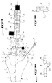
- Figure 1 is a schematic perspective view of a first embodiment of the ancillary device of the invention.
- Figure 2 is a schematic perspective view of the lower femoral end in which is made an imprint for receiving a femoro-patellar prosthesis of the invention.
- Figure 3 is a schematic perspective view of a femoro-patellar prosthesis of the invention.
- FIG. 4 is a side view along arrow XII of the femoro-patellar prosthesis of FIG. 3.
- Figure 5 is a schematic perspective view showing the step of drilling the distal end of the femur along its anatomical axis.
- FIG. 6 is a schematic perspective view of an intramedullary guide of the ancillary device of the invention, implanted in the intramedullary canal of the femur of FIG. 5.
- Figure 7 is a schematic perspective view of a first cutting tool of the ancillary device of the invention.
- Figure 8 is a schematic perspective view of a second cutting tool of the ancillary device of the invention.
- FIG. 9 is a top view of a support of the ancillary device of the invention supported by the intramedullary guide of FIG. 6.
- FIG. 9A is a plan view of the sliding element of the elongated plate mounted on the support of FIG. 9.
- FIG. 9B is a perspective view of the articulated element associated with the sliding element of FIG. 9A.
- FIG. 10 is a top view of an alternative embodiment of the ancillary device of the invention, after assembly of a cutting guide on the support illustrated in FIG. 9.
- Figure 11 is a side elevational view of the ancillary device of Figure 10, associated with the cutting tool shown in Figure 7 to form a main bearing surface in the femoral trochlea.
- Figure 12 is a side elevational view of the ancillary device of Figure 11, associated with a template for adjusting the position of the cutting guide.
- the ancillary device of the invention consists of a cutting tool forming rape 1 and an apparatus 2 for resection of the femoral trochlea.
- the sliding element 9 shown more clearly in FIG. 9A, has an oblong slot 9b for receiving the threaded rod of the thumb wheel 11 and longitudinally adjusting the position of the element 9 relative to the element 10 of the elongated plate 6 , and a lateral rim 9c projecting from the plane of the sliding element 9 to serve as a stop and longitudinal guide on the element 10.
- the articulated element 10 shown more clearly in FIG. 9B, has a general T shape, the lateral branches 10a of which are drilled to receive the threaded rod of the knurl 11 through the oblong opening 9b and the core 10b of which is articulated at its free end around the aforementioned axis 15.
- FIGS. 1 and 2 show the trochlear impression 36 produced in the femoral end 4a by means of the ancillary device of the invention.
- This trochlear impression 36 is formed by a main support surface 37 which is flat and tangent to the anterior cortex 16 and which is extended longitudinally by an inclined support surface 38 substantially parallel to the intracondylar region 39 (see FIGS. 5 and 6) of the femoral trochlea and a median groove 40 formed deeper in the distal femoral end 4a.
- the groove 40 here has an inclination substantially identical to the inclination of the inclined bearing surface 38, but it could alternatively be produced in the main bearing surface 37 or in the two bearing surfaces 37 and 38.
- the bearing surfaces 37 and 38 are limited to the middle and front part of the femoral end and longitudinally bordered on their sides by a surface 36a substantially perpendicular to said bearing surfaces and preserving the integrity of the anterior end 7a condyles 7 and cartilages covering them.
- Figures 3 and 4 show a particular embodiment of a femoro-patellar or trochlear prosthesis 42 intended to reconstruct the area of the knee joint receiving the kneecap (not shown).
- the prosthesis 42 has a rear face 42a and lateral faces 42b of a shape respectively adapted to the bearing surfaces 37 and 38 and to the surface 36a of the trochlear impression 36, from which the rear face 42a protrudes a central rib 43 intended to be housed in the groove 40 of the cavity 36 and two pins 44 intended to be housed in the aforesaid orifices 41, said lateral faces 42b having a different height from one side to the other.
- the surgeon comes to drill, from the entry point 45 (see Figures 2 and 5), the intercondylar region 39 of the trochlea to reproduce the anatomical axis of the femur, using a drill 46 (partially shown).
- the rod of the intramedullary guide 3 has a curvature 3b, the convexity of which is turned towards the rear face of the femur 4, to release sufficient space to allow the rape 1 to evolve when it is guided in the inclined housing 35 of the frame 28 .
- the support 17 is then placed on the end 3a of the intramedullary guide 3, as shown in FIG. 9, and a knurl 47 immobilizes the rod 3 in the main body 19b of the lower bracket 19.
- the elongated plate 6 is pressed against the condyles 7 along the bicondylar line 8 by rotating the articulated element 10 around the axis 15 and sliding the arm 13 in the lower end 19a of the bracket 19.
- knobs used in the ancillary device shown here, as well as the different slide links can be replaced by any other equivalent means.
- the surgeon slides the element 9 on a branch 10a of the element 10 until the longitudinal end flange 9a comes opposite a condyle 7, laterally so that the nails 12 do not damage the cartilage area 48 of the distal end 4a of the femur 4.
- the nails 12 and possibly the end flange 9a are provided oblique with respect to the anatomical axis 5 so that the nails 12 are implanted laterally in the condyles 7.
- the other branch 10a of the element 10 is left free to provide sufficient space for the tendons of the joint.
- the dimension of the feeler 30 is determined so that the distance between the main guide surface 33a and the trochlean area to be grated is automatically adjusted by abutment of the feeler 30, the size of the feeler 30 being adapted to the radius of the grate 1 used.
- a pair of shims 50 are installed in the housings 35 in an inclined U, so that the upper flat face 50a of the wedges 50 define a single plane with the main guide surface 33a of the side members 33.
- wedges 50 make it possible to cut the femoral trochlea in two stages, first along a plane tangent to the anterior cortex 16, then along an inclined plane parallel to the intercondylar region 39 of the femur. These fictitious section planes are shown in phantom in Figure 11.
- the rape 1 is arranged in the vicinity of the front end 28a of the frame 28, the drive shaft 34 being guided by the main surface 33a of the side members 33, the upper bracket 29 serving as an upper stop in the case of a vertical movement of the motor shaft 34.
- the front end 28a has a protrusion which projects upwards and serves as a front stop for the motor shaft 34.
- stirrup 29 is open at the front to allow rapid installation and removal of the rape 1 on the frame 28.
- the spacing between the side members 33 and the upper stirrup 29 can be slightly greater than the diameter of the motor shaft 34 to allow a plastic ring 53 to be inserted (see FIG. 8).
- This ring 53 is fitted on the motor shaft 34 to reduce friction and improve the timing of the latter in the cutting guide 26 by means of the portion 53b of smaller diameter of the ring, the portion 53a of larger diameter of the ring ensuring good centering of the cutting tool.
- the free ends 34a of the motor shaft 34 have a parallelepiped shape for their connection for example to a drive device, not shown.
- the cutting step illustrated in FIG. 11 forms the main bearing surface 37 and brings the anterior face of the femoral epiphysis to the same level as the anterior cortex 16.
- the template 51 has a smooth external surface intended to come to bear against the inclined trochlear area 39.
- the radius of the template 51 is equal to the radius of the rape 1 minus the maximum thickness of the prosthesis 42 to implant the trochlea.
- the surgeon finally uses the cutting tool 52 illustrated in FIG. 8, in the form of a toothed wheel, to form the groove 40 in the inclined bearing surface 38 of the trochlear impression 36, after having removed the upper stirrup 29 .
- the toothed wheel 52 may have a diameter greater than the above-mentioned rape 1 and adapted to the depth of the groove 40 to be dug, in order to avoid the use of a new drilling template.
- the orifices 41 are optionally made with conventional drilling means.
- the stability of the prosthesis 42 is ensured by the very precise cutting of the trochlear impression 36 and by the rib 43 and possibly the pins 41.
Landscapes
- Health & Medical Sciences (AREA)
- Life Sciences & Earth Sciences (AREA)
- Surgery (AREA)
- Orthopedic Medicine & Surgery (AREA)
- Veterinary Medicine (AREA)
- General Health & Medical Sciences (AREA)
- Oral & Maxillofacial Surgery (AREA)
- Engineering & Computer Science (AREA)
- Biomedical Technology (AREA)
- Heart & Thoracic Surgery (AREA)
- Public Health (AREA)
- Animal Behavior & Ethology (AREA)
- Molecular Biology (AREA)
- Nuclear Medicine, Radiotherapy & Molecular Imaging (AREA)
- Medical Informatics (AREA)
- Dentistry (AREA)
- Physical Education & Sports Medicine (AREA)
- Cardiology (AREA)
- Transplantation (AREA)
- Vascular Medicine (AREA)
- Surgical Instruments (AREA)
- Prostheses (AREA)
Applications Claiming Priority (2)
| Application Number | Priority Date | Filing Date | Title |
|---|---|---|---|
| FR9407392A FR2721202B1 (fr) | 1994-06-16 | 1994-06-16 | Prothèse fémoro-patellaire et dispositif ancillaire pour former une empreinte trochléenne de réception de cette prothèse. |
| FR9407392 | 1994-06-16 |
Publications (1)
| Publication Number | Publication Date |
|---|---|
| EP0687448A1 true EP0687448A1 (de) | 1995-12-20 |
Family
ID=9464297
Family Applications (1)
| Application Number | Title | Priority Date | Filing Date |
|---|---|---|---|
| EP95401387A Withdrawn EP0687448A1 (de) | 1994-06-16 | 1995-06-14 | Femoral-patellare Prothese und Hilfseinrichtung zur Herstellung von trochlearen Abdrücken zur Aufnahme einer solchen Prothese |
Country Status (2)
| Country | Link |
|---|---|
| EP (1) | EP0687448A1 (de) |
| FR (1) | FR2721202B1 (de) |
Cited By (15)
| Publication number | Priority date | Publication date | Assignee | Title |
|---|---|---|---|---|
| WO2009037471A3 (en) * | 2007-09-21 | 2009-06-04 | Depuy Int Ltd | Intramedullary rod instrument |
| EP2106756A1 (de) * | 2008-04-04 | 2009-10-07 | DePuy Products, Inc. | Knochenschneideanordnung |
| WO2012066305A1 (en) * | 2010-11-18 | 2012-05-24 | Depuy (Ireland) | Surgical instrument system, surgical alignment guide and surgical rod |
| US8523869B2 (en) | 2005-05-20 | 2013-09-03 | Smith & Nephew, Inc. | Patello-femoral joint implant and instrumentation |
| US9119635B2 (en) | 2010-11-18 | 2015-09-01 | Depuy (Ireland) | Surgical cutting guide, surgical alignment guide and surgical instrument system |
| US9364243B2 (en) | 2010-11-18 | 2016-06-14 | Depuy (Ireland) | Angular adjustment mechanism, surgical alignment guide and surgical instrument assembly |
| CN106137313A (zh) * | 2016-07-22 | 2016-11-23 | 田�文明 | 一种膝关节置换术可见骨赘刮除装置 |
| CN107296642A (zh) * | 2017-05-15 | 2017-10-27 | 海安国洋机械科技有限公司 | 一种新型锉刀 |
| CN108670390A (zh) * | 2018-05-29 | 2018-10-19 | 上海市杨浦区中心医院(同济大学附属杨浦医院) | 改良式膝关节单髁置换术股骨髓内导杆定位系统 |
| US10299801B2 (en) | 2013-04-12 | 2019-05-28 | Depuy Ireland Unlimited Company | Distal femoral jig assembly |
| CN110051406A (zh) * | 2019-05-15 | 2019-07-26 | 天津正天医疗器械有限公司 | 一种髁间截骨器 |
| USD894385S1 (en) | 2017-10-27 | 2020-08-25 | Orthopediatrics Corp. | Orthopedic tool |
| CN114343777A (zh) * | 2021-12-31 | 2022-04-15 | 刘亚坤 | 半月板成型刀 |
| CN114916988A (zh) * | 2022-06-13 | 2022-08-19 | 北京大学第三医院(北京大学第三临床医学院) | 一种骨切割机构 |
| CN117982191A (zh) * | 2023-09-07 | 2024-05-07 | 北京纳通医疗科技控股有限公司 | 股骨定位器和磨钻定位系统 |
Families Citing this family (5)
| Publication number | Priority date | Publication date | Assignee | Title |
|---|---|---|---|---|
| US5824098A (en) * | 1994-10-24 | 1998-10-20 | Stein; Daniel | Patello-femoral joint replacement device and method |
| DE19544084C1 (de) * | 1995-11-27 | 1997-05-28 | Uwe Hollmann | Instrumentarium zum knochenschonenden Resezieren für den Einsatz einer Kniegelenksendo- oder Totalendoprothese |
| WO1997043985A1 (en) * | 1996-05-23 | 1997-11-27 | Daniel Stein | Patello-femoral joint replacement device and method |
| EP1129677A3 (de) | 2000-02-29 | 2003-04-02 | Brehm, Peter | Instrumentarium zur Herstellung der Befestigungsflächen für eine Kniegelenkendoprothese |
| DE10207034C1 (de) * | 2002-02-20 | 2003-10-02 | Aesculap Ag & Co Kg | Führung für ein drehbares chirurgisches Bearbeitungswerkzeug |
Citations (6)
| Publication number | Priority date | Publication date | Assignee | Title |
|---|---|---|---|---|
| EP0121142A1 (de) * | 1983-03-09 | 1984-10-10 | Dow Corning Corporation | Vorrichtung zur Bildung der Knieschenkeloberfläche |
| WO1991004715A1 (fr) * | 1989-09-29 | 1991-04-18 | Georges Mendolia | Prothese femoro-patellaire et ses dispositifs de mise en place |
| FR2676641A1 (fr) * | 1990-11-29 | 1992-11-27 | Vialla Jean Marie | Prothese femoro-patellaire. |
| US5176684A (en) * | 1992-02-20 | 1993-01-05 | Dow Corning Wright | Modular shaping and trial reduction guide for implantation of posterior-stabilized femoral prosthesis and method of using same |
| DE9301611U1 (de) * | 1992-02-07 | 1993-06-03 | Howmedica International Inc., Shannon, Clare | Orthopädisches Instrument |
| WO1994008528A1 (en) * | 1992-10-08 | 1994-04-28 | Wright Medical Technology, Inc. | External alignment system |
-
1994
- 1994-06-16 FR FR9407392A patent/FR2721202B1/fr not_active Expired - Fee Related
-
1995
- 1995-06-14 EP EP95401387A patent/EP0687448A1/de not_active Withdrawn
Patent Citations (6)
| Publication number | Priority date | Publication date | Assignee | Title |
|---|---|---|---|---|
| EP0121142A1 (de) * | 1983-03-09 | 1984-10-10 | Dow Corning Corporation | Vorrichtung zur Bildung der Knieschenkeloberfläche |
| WO1991004715A1 (fr) * | 1989-09-29 | 1991-04-18 | Georges Mendolia | Prothese femoro-patellaire et ses dispositifs de mise en place |
| FR2676641A1 (fr) * | 1990-11-29 | 1992-11-27 | Vialla Jean Marie | Prothese femoro-patellaire. |
| DE9301611U1 (de) * | 1992-02-07 | 1993-06-03 | Howmedica International Inc., Shannon, Clare | Orthopädisches Instrument |
| US5176684A (en) * | 1992-02-20 | 1993-01-05 | Dow Corning Wright | Modular shaping and trial reduction guide for implantation of posterior-stabilized femoral prosthesis and method of using same |
| WO1994008528A1 (en) * | 1992-10-08 | 1994-04-28 | Wright Medical Technology, Inc. | External alignment system |
Cited By (30)
| Publication number | Priority date | Publication date | Assignee | Title |
|---|---|---|---|---|
| US8523869B2 (en) | 2005-05-20 | 2013-09-03 | Smith & Nephew, Inc. | Patello-femoral joint implant and instrumentation |
| CN101801286B (zh) * | 2007-09-21 | 2012-07-04 | 德普伊国际有限公司 | 髓内杆器械 |
| US9314282B2 (en) | 2007-09-21 | 2016-04-19 | Depuy (Ireland) | Intramedullary rod instrument |
| WO2009037471A3 (en) * | 2007-09-21 | 2009-06-04 | Depuy Int Ltd | Intramedullary rod instrument |
| JP2010540007A (ja) * | 2007-09-21 | 2010-12-24 | デピュー インターナショナル リミテッド | 髄内ロッド器具 |
| US8636741B2 (en) | 2007-09-21 | 2014-01-28 | Depuy International Limited | Intramedullary rod instrument |
| AU2008300430B2 (en) * | 2007-09-21 | 2013-10-03 | Depuy International Ltd | Intramedullary rod instrument |
| US8845643B2 (en) | 2008-04-04 | 2014-09-30 | DePuy Synthes Products, LLC | Humeral rotating burr guide |
| EP2206468A1 (de) * | 2008-04-04 | 2010-07-14 | DePuy Products, Inc. | Knochenschneideanordnung |
| US8231630B2 (en) | 2008-04-04 | 2012-07-31 | Depuy Products, Inc. | Humeral rotating burr guide |
| EP2106756A1 (de) * | 2008-04-04 | 2009-10-07 | DePuy Products, Inc. | Knochenschneideanordnung |
| US8114087B2 (en) | 2008-04-04 | 2012-02-14 | Depuy Products, Inc. | Humeral rotating burr guide |
| EP2308396A1 (de) * | 2008-04-04 | 2011-04-13 | DePuy Products, Inc. | Knochenschneideanordnung |
| US8657828B2 (en) | 2008-04-04 | 2014-02-25 | DePuy Synthes Products, LLC | Humeral rotating burr guide |
| US9364243B2 (en) | 2010-11-18 | 2016-06-14 | Depuy (Ireland) | Angular adjustment mechanism, surgical alignment guide and surgical instrument assembly |
| CN103220992B (zh) * | 2010-11-18 | 2015-11-25 | 德普伊(爱尔兰)有限公司 | 手术仪器系统、手术对准导引件和手术杆 |
| WO2012066305A1 (en) * | 2010-11-18 | 2012-05-24 | Depuy (Ireland) | Surgical instrument system, surgical alignment guide and surgical rod |
| CN103220992A (zh) * | 2010-11-18 | 2013-07-24 | 德普伊(爱尔兰)有限公司 | 手术仪器系统、手术对准导引件和手术杆 |
| US9119635B2 (en) | 2010-11-18 | 2015-09-01 | Depuy (Ireland) | Surgical cutting guide, surgical alignment guide and surgical instrument system |
| US10299801B2 (en) | 2013-04-12 | 2019-05-28 | Depuy Ireland Unlimited Company | Distal femoral jig assembly |
| US10952745B2 (en) | 2013-04-12 | 2021-03-23 | Depuy Ireland Unlimited Company | Distal femoral jig assembly |
| CN106137313A (zh) * | 2016-07-22 | 2016-11-23 | 田�文明 | 一种膝关节置换术可见骨赘刮除装置 |
| CN106137313B (zh) * | 2016-07-22 | 2018-12-18 | 田�文明 | 一种膝关节置换术可见骨赘刮除装置 |
| CN107296642A (zh) * | 2017-05-15 | 2017-10-27 | 海安国洋机械科技有限公司 | 一种新型锉刀 |
| USD894385S1 (en) | 2017-10-27 | 2020-08-25 | Orthopediatrics Corp. | Orthopedic tool |
| CN108670390A (zh) * | 2018-05-29 | 2018-10-19 | 上海市杨浦区中心医院(同济大学附属杨浦医院) | 改良式膝关节单髁置换术股骨髓内导杆定位系统 |
| CN110051406A (zh) * | 2019-05-15 | 2019-07-26 | 天津正天医疗器械有限公司 | 一种髁间截骨器 |
| CN114343777A (zh) * | 2021-12-31 | 2022-04-15 | 刘亚坤 | 半月板成型刀 |
| CN114916988A (zh) * | 2022-06-13 | 2022-08-19 | 北京大学第三医院(北京大学第三临床医学院) | 一种骨切割机构 |
| CN117982191A (zh) * | 2023-09-07 | 2024-05-07 | 北京纳通医疗科技控股有限公司 | 股骨定位器和磨钻定位系统 |
Also Published As
| Publication number | Publication date |
|---|---|
| FR2721202A1 (fr) | 1995-12-22 |
| FR2721202B1 (fr) | 1996-10-04 |
Similar Documents
| Publication | Publication Date | Title |
|---|---|---|
| FR2721202A1 (fr) | Prothèse fémoro-patellaire et dispositif ancillaire pour former une empreinte trochléenne de réception de cette prothèse. | |
| EP1643916B1 (de) | Vorrichtung zur unterstützung bei der implantation einer knietotalprothese | |
| EP1952771B1 (de) | Gesamtheit der chirurgischen Instrumente zum Einsetzen einer Schulterprothese | |
| EP0871419B1 (de) | Zwischenwirbelimplantat als wirbelkäfig ausgebildet | |
| EP1508316B1 (de) | Metatarsalphalangeale Vollprothese und Hilfsgerät zum Einsetzen einer solchen Prothese. | |
| EP1732448B1 (de) | Hilfsanordnung zur implantation von knieprothesen | |
| FR2808994A1 (fr) | Prothese d'articulation | |
| EP2277460A1 (de) | Chirurgische Instrumentierung zur Vorbereitung des Einsetzens einer Knieprothese | |
| FR2926719A1 (fr) | Ensemble compose d'une embase tibiale et d'un insert tibial et prothese comprenant un tel ensemble | |
| FR2660856A1 (fr) | Prothese radio-cubitale inferieure. | |
| FR2679766A1 (fr) | Dispositif de pose d'une prothese du genou. | |
| FR2776176A1 (fr) | Systeme de positionnement d'un guide de coupe osseuse pour la preparation a la pose d'une prothese de genou | |
| FR2649604A1 (fr) | Instrument ancillaire chirurgical de reperage de l'entree et de la direction du tunnel d'insertion femorale d'un neo-ligament dans des conditions d'isometrie totale | |
| EP2330984A1 (de) | Zubehörset zur implantation einer knieprothese | |
| FR2635675A1 (fr) | Instrumentation ancillaire pour l'implantation d'une prothese totale du genou et secondairement pour osteotomies de correction axiale | |
| FR2759900A1 (fr) | Systeme pour le remplacement de l'articulation de la cheville | |
| WO1995024874A1 (fr) | Ensemble prothetique pour l'articulation du genou | |
| FR2802080A1 (fr) | Ensemble pour la mise en place d'une tige femorale de prothese de hanche sur un femur | |
| CA2274935C (fr) | Ancillaire pour la preparation de la pose d'une prothese de genou | |
| FR2630639A1 (fr) | Dispositif de prothese partielle du genou | |
| FR2732210A1 (fr) | Appareil pour la preparation d'une rotule en vue de la mise en place d'un implant patellaire | |
| FR2938178A1 (fr) | Ancillaire pour la preparation osseuse d'un femur destine a recevoir un composant femoral prothetique | |
| FR2948275A1 (fr) | Instrumentation chirurgicale de preparation du femur pour la mise en place d'un transplant double faisceau destine a reconstruire un ligament croise anterieur | |
| EP0983750B1 (de) | Hilfsinstrument zur Vorbereitung des Einsetzens einer Kniescheiben-Prothese | |
| FR2628316A1 (fr) | Prothese totale du genou |
Legal Events
| Date | Code | Title | Description |
|---|---|---|---|
| PUAI | Public reference made under article 153(3) epc to a published international application that has entered the european phase |
Free format text: ORIGINAL CODE: 0009012 |
|
| AK | Designated contracting states |
Kind code of ref document: A1 Designated state(s): BE CH ES FR IT LI |
|
| STAA | Information on the status of an ep patent application or granted ep patent |
Free format text: STATUS: THE APPLICATION IS DEEMED TO BE WITHDRAWN |
|
| 18D | Application deemed to be withdrawn |
Effective date: 19960621 |