EP0687582A1 - Reifenlauffläche - Google Patents
Reifenlauffläche Download PDFInfo
- Publication number
- EP0687582A1 EP0687582A1 EP95107319A EP95107319A EP0687582A1 EP 0687582 A1 EP0687582 A1 EP 0687582A1 EP 95107319 A EP95107319 A EP 95107319A EP 95107319 A EP95107319 A EP 95107319A EP 0687582 A1 EP0687582 A1 EP 0687582A1
- Authority
- EP
- European Patent Office
- Prior art keywords
- tread
- rib
- grooves
- ribs
- edge
- Prior art date
- Legal status (The legal status is an assumption and is not a legal conclusion. Google has not performed a legal analysis and makes no representation as to the accuracy of the status listed.)
- Granted
Links
- 230000005484 gravity Effects 0.000 description 2
- 238000004804 winding Methods 0.000 description 2
- 230000002159 abnormal effect Effects 0.000 description 1
- 230000001154 acute effect Effects 0.000 description 1
- 230000002411 adverse Effects 0.000 description 1
- 230000003542 behavioural effect Effects 0.000 description 1
- 238000012937 correction Methods 0.000 description 1
- 230000003247 decreasing effect Effects 0.000 description 1
- 230000000750 progressive effect Effects 0.000 description 1
- 230000002787 reinforcement Effects 0.000 description 1
- 238000005096 rolling process Methods 0.000 description 1
- 230000002459 sustained effect Effects 0.000 description 1
Images


Classifications
-
- B—PERFORMING OPERATIONS; TRANSPORTING
- B60—VEHICLES IN GENERAL
- B60C—VEHICLE TYRES; TYRE INFLATION; TYRE CHANGING; CONNECTING VALVES TO INFLATABLE ELASTIC BODIES IN GENERAL; DEVICES OR ARRANGEMENTS RELATED TO TYRES
- B60C11/00—Tyre tread bands; Tread patterns; Anti-skid inserts
- B60C11/03—Tread patterns
- B60C11/13—Tread patterns characterised by the groove cross-section, e.g. for buttressing or preventing stone-trapping
- B60C11/1376—Three dimensional block surfaces departing from the enveloping tread contour
- B60C11/1392—Three dimensional block surfaces departing from the enveloping tread contour with chamfered block edges
-
- B—PERFORMING OPERATIONS; TRANSPORTING
- B60—VEHICLES IN GENERAL
- B60C—VEHICLE TYRES; TYRE INFLATION; TYRE CHANGING; CONNECTING VALVES TO INFLATABLE ELASTIC BODIES IN GENERAL; DEVICES OR ARRANGEMENTS RELATED TO TYRES
- B60C11/00—Tyre tread bands; Tread patterns; Anti-skid inserts
- B60C11/03—Tread patterns
- B60C11/0304—Asymmetric patterns
-
- B—PERFORMING OPERATIONS; TRANSPORTING
- B60—VEHICLES IN GENERAL
- B60C—VEHICLE TYRES; TYRE INFLATION; TYRE CHANGING; CONNECTING VALVES TO INFLATABLE ELASTIC BODIES IN GENERAL; DEVICES OR ARRANGEMENTS RELATED TO TYRES
- B60C11/00—Tyre tread bands; Tread patterns; Anti-skid inserts
- B60C11/03—Tread patterns
- B60C11/0306—Patterns comprising block rows or discontinuous ribs
- B60C11/0309—Patterns comprising block rows or discontinuous ribs further characterised by the groove cross-section
-
- B—PERFORMING OPERATIONS; TRANSPORTING
- B60—VEHICLES IN GENERAL
- B60C—VEHICLE TYRES; TYRE INFLATION; TYRE CHANGING; CONNECTING VALVES TO INFLATABLE ELASTIC BODIES IN GENERAL; DEVICES OR ARRANGEMENTS RELATED TO TYRES
- B60C11/00—Tyre tread bands; Tread patterns; Anti-skid inserts
- B60C11/03—Tread patterns
- B60C11/04—Tread patterns in which the raised area of the pattern consists only of continuous circumferential ribs, e.g. zig-zag
- B60C11/042—Tread patterns in which the raised area of the pattern consists only of continuous circumferential ribs, e.g. zig-zag further characterised by the groove cross-section
Definitions
- the present invention relates to a tread for a passenger tire, intended to travel at high speed in a sustained manner.
- the tread of such a tire generally comprises several circumferential grooves, either straight or zigzag, delimiting ribs between them.
- Said ribs can be, at least some, subdivided into blocks by means of grooves and / or transverse incisions.
- the subject of the invention is a tire having an asymmetrical tread, the mounting of four of said tires on a vehicle allowing the improvement of the cornering behavior of said vehicle, whether on dry road or on wet road.
- Applications JP61 / 16110, JP61 / 9315, JP57 / 4409 relate more particularly to the circumferential grooves of a tread, for which it is possible, in order to remedy abnormal wear, to modify the amplitude of the zigzag forming said grooves, or to modify the width of the ribs arranged between said grooves, or to modify the width of said grooves. It is also known, in order to improve the behavior of a vehicle on dry and / or wet roads, to provide different rates of notching between the two half-treads, as mentioned in applications JP02 / 225103 and 57/147901. Finally, the combination of the characteristics cited with other characteristics such as, for example, the angular orientation of the transverse grooves, the number of blocks delimited by the grooves, and so on, makes it possible to design treads of more and more specialized and complicated.
- a tire comprises a tread comprising at least two circumferential grooves, delimiting at least three ribs, two of which are said to be lateral, and the other (s) central (s) and intermediate.
- Said tread is characterized in that the edge formed by the surface of at least one central or intermediate rib and the wall of the circumferential groove, delimiting said rib and closest axially to the outside of the tread, is truncated by a surface, said outer side being identified by a marking made on the sidewall of the tire.
- the outer side of the tread should be understood to mean the side of said strip axially furthest from the center of gravity of the vehicle on which the tire having said strip is mounted.
- Truncation can be done by a flat surface, and the edge is then said to be chamfered. Truncation can also be advantageously done by a curved surface and there is then connection leave.
- the curved surface ensuring the connection between the tread surface and the surface of the wall of the circumferential groove concerned has, seen in a radial plane, a tangent circular outline, on the one hand to the meridian profile of the tread, on the other hand to the trace on said plane of the wall of the groove.
- the circular path of said connecting surface advantageously has a radius of curvature between 1 and 0.5 times the depth of the axially adjacent groove. Tires with treads having such curvature characteristics give the equipped vehicle a better positioning of said vehicle on its trajectory at the start of a turn, as well as a much more progressive turn winding. It is possible to define the winding in a turn of a vehicle as being the ability of said vehicle to follow its trajectory without the need for permanent corrections at the wheel.
- each rib having a truncated edge is provided with transverse grooves opening at least on the circumferential groove axially adjacent to the edge.
- a transverse groove is understood to mean a rectilinear groove or one which can be assimilated to a series of rectilinear segments making angles between 0 ° and 45 ° with the meridian direction of the tire.
- the rubber corners delimited by the walls respectively of the circumferential grooves and the transverse grooves are then advantageously truncated according to frustoconical surfaces, which allows in particular a better seating of the rubber corners, delimited by the walls of grooves which form between them angles acute, while the vehicle is traveling on its cornering trajectory.
- the behavior of the vehicle when cornering can be further improved if the outer lateral rib of the tread has a lower notch rate than the notch rate of the inner lateral rib of said band.
- the ratio of the highest rate to the lowest is advantageously between 1 and 4, the highest rate remaining between 3% and 6%, the lowest rate remaining between 1% and 5%.
- the tread (1) of FIGS. 1A and 1B comprises two circumferential and rectilinear grooves (3A) and (3B) which subdivide said strip (1) into three ribs (2A, 2B, 2C) of blocks (20A, 20) or quasi-blocks (20B).
- the lateral rib (2A) is located on the inside, it is the rib closest to the center of gravity of the vehicle on which a tire will be mounted with such a tread (1).
- the lateral rib (2B) is the so-called outer rib, this rib having a rate of notching lower than the rate of notching of the inner lateral rib (2A) in the ratio of 1 to 4. It is necessary to understand by rate of notching of the rib, the ratio of the notched surface of said rib of said strip to the total contact surface between the tire and the ground.
- the rib (2C) is axially delimited by two circumferential grooves (3A) and (3B), is formed of blocks (20), separated circumferentially from each other by transverse grooves (21) opening onto the two grooves (3A) and (3B ), and internally provided with one or more incisions (22).
- the edge (10) formed by the central rib (2C) and the wall of the circumferential groove (3B), a groove delimiting said rib and being axially closest to the outside of the tread, is truncated by a surface.
- cylindrical (11) having, seen in meridian section (FIG. 1B), a radius of curvature R, equal to 0.75 times the depth H of the groove (3B).
- the corners (12) and (13) of rubber, delimited by the walls respectively of the transverse grooves (21) and the circumferential groove (3B) are truncated according to frustoconical surfaces of the same references (12) and (13), (figure 4).
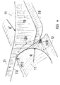
- the frustoconical surface (12) is generated by the generator OT around the point 0, said generator OT being the line segment joining the point of tangency T, of the trace TR on the tread surface of the planar wall (210) of the transverse groove (21) with the intersection curve (120) of the cylindrical surface (11), through which the edge (10) has been truncated with said wall (210), at the point of tangency O of said curve intersection (120) with the wall (30B) of the adjacent circumferential groove.
- the rotation of said OT generator is such that the frustoconical surface generated (12) forms with the cylindrical surface (11) of truncates an arc of a circle of radius equal to R.
- the radius R is equal to 5 mm, while the radius R 'is three times greater, that is to say equal to 15 mm
- the lower notch rate of the rib (2B) is obtained mainly, firstly by the fact that the transverse grooves (21B) only open on the outer edge of the tread while the transverse grooves (21A) of the inner rib (2A) open on the inner edge of the tread and on the circumferential groove (3A), and on the other hand by the fact that the quasi-blocks (20B) are provided with incisions (22B) while the blocks (20A) are provided inside grooves (22A) having a width approximately equal to 4 times the width of an incision (22B).
- Other characteristics can contribute to obtaining such a difference in rate of notching, such as for example, the characteristics of junction of the walls of the lateral grooves with the edge of the tread: the rubber corners formed by the leading (or trailing according to the direction of rotation) walls of the transverse grooves (21A) of the rib (2A) are voluntarily more truncated than the rubber corners formed by the leading (or trailing) walls of the transverse grooves (21B) of the rib (2B).
- Said fine grooves or incisions, respectively (22A), (22B), are not parallel to the transverse grooves, respectively (21A), (21B) of the ribs (2A) and (2B), and form with the circumferential direction an angle of 75 °, less than the 85 ° angle made by the transverse grooves with said direction; in this example the angle difference is equal to 10 °.
- FIGS. 2A and 2B represent a second variant which differs from the previous one by the following main characteristics.
- the tread comprises four circumferential grooves (3A, 3B, 3C, 3D) delimiting with its edges five ribs: two lateral ribs (2A, 2B), two ribs (2I) called intermediate, and a central rib (2C).
- the edges formed respectively by the surfaces of the central (2C) and intermediate (2I) ribs and the walls of the grooves delimiting them and closest to the outer edge of the tread of the tire are truncated by a surface, which is, in the case present, a flat surface, as shown in Figure 2B.
- the notch rate of the outer side rib (2B) is similarly lower than the corresponding rate of the inner side rib (2A).
- the asymmetry of the notching rates is, in this second variant, accentuated by the fact that the notching rate of the intermediate rib (2I) closest axially to the outside of the tire is also lower than the rate of notching of the intermediate rib (2I) axially closest to the inner side of the tire, the transverse grooves (21'I) of the intermediate rib (2I) said to be internal, opening onto the two axially adjacent grooves (3A) and (3B) and are continuous, while the intermediate rib (2I) called external comprises only transverse quasi-grooves (21''I) that is to say transversely discontinuous grooves.
- FIGS. 3A and 3B show a variant of the tread comprising five circumferential grooves (3A, 3I, 3C, 3I, 3B) thus delimiting six ribs, two lateral ribs (2A, 2B), two intermediate ribs (2I) and two ribs central (2C).
- the edge formed by the surface of the intermediate rib (2I) called inner (closest to the inner side) and the wall of the axially adjacent groove called inner (3I), the more near the outside edge of the tire tread, and on the other hand the edge formed by the surface of the central rib (2C), closest to the outside edge of the tire and the wall of the axially adjacent groove called the outside (3I), the closest to said outer edge of the tire, are truncated by a surface, which is, as in the case shown in FIG. 1A, a cylindrical surface (11), having, seen in meridian section (FIG. 3B), a radius of curvature R, equal to 0.75 times the common depth H of the grooves (3I).
Landscapes
- Engineering & Computer Science (AREA)
- Mechanical Engineering (AREA)
- Tires In General (AREA)
Applications Claiming Priority (2)
| Application Number | Priority Date | Filing Date | Title |
|---|---|---|---|
| FR9407544 | 1994-06-14 | ||
| FR9407544A FR2720979A1 (fr) | 1994-06-14 | 1994-06-14 | Bande de roulement pour pneumatique. |
Publications (2)
| Publication Number | Publication Date |
|---|---|
| EP0687582A1 true EP0687582A1 (de) | 1995-12-20 |
| EP0687582B1 EP0687582B1 (de) | 1998-11-11 |
Family
ID=9464417
Family Applications (1)
| Application Number | Title | Priority Date | Filing Date |
|---|---|---|---|
| EP19950107319 Expired - Lifetime EP0687582B1 (de) | 1994-06-14 | 1995-05-15 | Reifenlauffläche |
Country Status (7)
| Country | Link |
|---|---|
| EP (1) | EP0687582B1 (de) |
| JP (1) | JPH07329516A (de) |
| BR (1) | BR9502787A (de) |
| CA (1) | CA2149715A1 (de) |
| DE (1) | DE69505891T2 (de) |
| ES (1) | ES2124933T3 (de) |
| FR (1) | FR2720979A1 (de) |
Cited By (9)
| Publication number | Priority date | Publication date | Assignee | Title |
|---|---|---|---|---|
| WO2004024473A1 (ja) * | 2002-09-10 | 2004-03-25 | The Yokohama Rubber Co.,Ltd. | 空気入りタイヤ |
| EP1410927A3 (de) * | 2002-10-15 | 2004-11-24 | The Goodyear Tire & Rubber Company | Reifenlauffläche mit abgefasten Profilelementen |
| EP1566291A4 (de) * | 2002-11-06 | 2008-08-27 | Bridgestone Corp | Pneumatischer reifen |
| EP1918130A4 (de) * | 2005-08-23 | 2009-06-10 | Bridgestone Corp | Luftreifen |
| US7673663B2 (en) * | 2005-06-30 | 2010-03-09 | Sumitomo Rubber Industries, Ltd. | Pneumatic tire with tread having non-linear rib |
| WO2010136084A1 (de) * | 2009-05-27 | 2010-12-02 | Continental Reifen Deutschland Gmbh | Fahrzeugluftreifen |
| WO2018059759A1 (de) * | 2016-09-30 | 2018-04-05 | Continental Reifen Deutschland Gmbh | Fahrzeugluftreifen |
| US20180207993A1 (en) * | 2015-07-27 | 2018-07-26 | The Yokohama Rubber Co., Ltd. | Pneumatic Tire |
| WO2023242787A1 (en) * | 2022-06-16 | 2023-12-21 | Pirelli Tyre S.P.A. | Tyre for vehicle wheels |
Families Citing this family (14)
| Publication number | Priority date | Publication date | Assignee | Title |
|---|---|---|---|---|
| JPH1148719A (ja) * | 1997-08-07 | 1999-02-23 | Bridgestone Corp | 重荷重用空気入りタイヤ |
| JP3378825B2 (ja) * | 1999-03-16 | 2003-02-17 | 住友ゴム工業株式会社 | 空気入りタイヤ |
| DE19937067A1 (de) * | 1999-08-05 | 2001-02-08 | Dunlop Gmbh | Fahrzeugreifen mit einer profilierten Lauffläche |
| JP4346227B2 (ja) * | 2000-09-18 | 2009-10-21 | 横浜ゴム株式会社 | 空気入りタイヤ |
| JP4295498B2 (ja) | 2002-12-13 | 2009-07-15 | 住友ゴム工業株式会社 | Atv用ラジアルタイヤ |
| JP4461746B2 (ja) * | 2003-09-10 | 2010-05-12 | 横浜ゴム株式会社 | 空気入りタイヤ |
| JP4744800B2 (ja) * | 2003-12-05 | 2011-08-10 | 株式会社ブリヂストン | 空気入りタイヤ |
| JP4661260B2 (ja) * | 2005-02-21 | 2011-03-30 | 横浜ゴム株式会社 | 空気入りタイヤ |
| JP4626333B2 (ja) * | 2005-02-21 | 2011-02-09 | 横浜ゴム株式会社 | 空気入りタイヤ |
| JP4717548B2 (ja) * | 2005-08-23 | 2011-07-06 | 株式会社ブリヂストン | 空気入りタイヤ |
| JP4909035B2 (ja) * | 2006-12-05 | 2012-04-04 | 株式会社ブリヂストン | 空気入りタイヤ |
| JP5695476B2 (ja) * | 2011-04-12 | 2015-04-08 | 住友ゴム工業株式会社 | 空気入りタイヤ |
| JP5462898B2 (ja) * | 2012-01-25 | 2014-04-02 | 住友ゴム工業株式会社 | 空気入りタイヤ |
| JP6031055B2 (ja) * | 2014-03-11 | 2016-11-24 | 住友ゴム工業株式会社 | 空気入りタイヤ |
Citations (10)
| Publication number | Priority date | Publication date | Assignee | Title |
|---|---|---|---|---|
| US3768535A (en) * | 1971-12-03 | 1973-10-30 | E Holden | Tire tread |
| JPS574409A (en) | 1980-06-11 | 1982-01-11 | Bridgestone Corp | Pneumatic radial tire for heavy car with unsymmetrical tread pattern |
| JPS57147901A (en) | 1981-03-10 | 1982-09-13 | Yokohama Rubber Co Ltd:The | Radial tire |
| JPS619315A (ja) | 1984-06-22 | 1986-01-16 | Sumitomo Rubber Ind Ltd | トラツク、バス用ラジアルタイヤ |
| JPS6116110A (ja) | 1984-06-30 | 1986-01-24 | Sumitomo Rubber Ind Ltd | トラツク、バス用ラジアルタイヤ |
| JPS6317102A (ja) | 1986-07-10 | 1988-01-25 | Bridgestone Corp | 重荷重用空気入りタイヤ |
| JPH02225103A (ja) | 1988-11-21 | 1990-09-07 | Sumitomo Rubber Ind Ltd | 車両用タイヤ |
| EP0428472A2 (de) * | 1989-11-15 | 1991-05-22 | The Goodyear Tire & Rubber Company | Asymmetrischer Reifen |
| JPH04193610A (ja) | 1990-11-28 | 1992-07-13 | Bridgestone Corp | 空気入りラジアルタイヤ |
| EP0578216A1 (de) * | 1992-07-10 | 1994-01-12 | Michelin Recherche Et Technique S.A. | Asymetrische Reifenlauffläche |
-
1994
- 1994-06-14 FR FR9407544A patent/FR2720979A1/fr active Pending
-
1995
- 1995-05-15 DE DE1995605891 patent/DE69505891T2/de not_active Expired - Fee Related
- 1995-05-15 EP EP19950107319 patent/EP0687582B1/de not_active Expired - Lifetime
- 1995-05-15 ES ES95107319T patent/ES2124933T3/es not_active Expired - Lifetime
- 1995-05-18 CA CA002149715A patent/CA2149715A1/fr not_active Abandoned
- 1995-06-13 BR BR9502787A patent/BR9502787A/pt not_active IP Right Cessation
- 1995-06-14 JP JP7147385A patent/JPH07329516A/ja active Pending
Patent Citations (10)
| Publication number | Priority date | Publication date | Assignee | Title |
|---|---|---|---|---|
| US3768535A (en) * | 1971-12-03 | 1973-10-30 | E Holden | Tire tread |
| JPS574409A (en) | 1980-06-11 | 1982-01-11 | Bridgestone Corp | Pneumatic radial tire for heavy car with unsymmetrical tread pattern |
| JPS57147901A (en) | 1981-03-10 | 1982-09-13 | Yokohama Rubber Co Ltd:The | Radial tire |
| JPS619315A (ja) | 1984-06-22 | 1986-01-16 | Sumitomo Rubber Ind Ltd | トラツク、バス用ラジアルタイヤ |
| JPS6116110A (ja) | 1984-06-30 | 1986-01-24 | Sumitomo Rubber Ind Ltd | トラツク、バス用ラジアルタイヤ |
| JPS6317102A (ja) | 1986-07-10 | 1988-01-25 | Bridgestone Corp | 重荷重用空気入りタイヤ |
| JPH02225103A (ja) | 1988-11-21 | 1990-09-07 | Sumitomo Rubber Ind Ltd | 車両用タイヤ |
| EP0428472A2 (de) * | 1989-11-15 | 1991-05-22 | The Goodyear Tire & Rubber Company | Asymmetrischer Reifen |
| JPH04193610A (ja) | 1990-11-28 | 1992-07-13 | Bridgestone Corp | 空気入りラジアルタイヤ |
| EP0578216A1 (de) * | 1992-07-10 | 1994-01-12 | Michelin Recherche Et Technique S.A. | Asymetrische Reifenlauffläche |
Non-Patent Citations (1)
| Title |
|---|
| PATENT ABSTRACTS OF JAPAN vol. 16, no. 523 (M - 1331) 27 October 1992 (1992-10-27) * |
Cited By (14)
| Publication number | Priority date | Publication date | Assignee | Title |
|---|---|---|---|---|
| WO2004024473A1 (ja) * | 2002-09-10 | 2004-03-25 | The Yokohama Rubber Co.,Ltd. | 空気入りタイヤ |
| CN100335300C (zh) * | 2002-09-10 | 2007-09-05 | 横滨橡胶株式会社 | 充气轮胎 |
| US7478657B2 (en) | 2002-09-10 | 2009-01-20 | The Yokohama Rubber Co., Ltd. | Pneumatic tire with ground contact surface of land portion having circular arcs |
| EP1410927A3 (de) * | 2002-10-15 | 2004-11-24 | The Goodyear Tire & Rubber Company | Reifenlauffläche mit abgefasten Profilelementen |
| US6983777B2 (en) | 2002-10-15 | 2006-01-10 | The Goodyear Tire & Rubber Company | Tire tread with multi-planar chamfers |
| EP1566291A4 (de) * | 2002-11-06 | 2008-08-27 | Bridgestone Corp | Pneumatischer reifen |
| AU2006201886B2 (en) * | 2005-06-30 | 2011-05-26 | Sumitomo Rubber Industries, Ltd. | Pneumatic tire |
| US7673663B2 (en) * | 2005-06-30 | 2010-03-09 | Sumitomo Rubber Industries, Ltd. | Pneumatic tire with tread having non-linear rib |
| EP1918130A4 (de) * | 2005-08-23 | 2009-06-10 | Bridgestone Corp | Luftreifen |
| WO2010136084A1 (de) * | 2009-05-27 | 2010-12-02 | Continental Reifen Deutschland Gmbh | Fahrzeugluftreifen |
| CN102448743B (zh) * | 2009-05-27 | 2014-10-15 | 大陆轮胎德国有限公司 | 车辆充气轮胎 |
| US20180207993A1 (en) * | 2015-07-27 | 2018-07-26 | The Yokohama Rubber Co., Ltd. | Pneumatic Tire |
| WO2018059759A1 (de) * | 2016-09-30 | 2018-04-05 | Continental Reifen Deutschland Gmbh | Fahrzeugluftreifen |
| WO2023242787A1 (en) * | 2022-06-16 | 2023-12-21 | Pirelli Tyre S.P.A. | Tyre for vehicle wheels |
Also Published As
| Publication number | Publication date |
|---|---|
| FR2720979A1 (fr) | 1995-12-15 |
| DE69505891T2 (de) | 1999-05-12 |
| JPH07329516A (ja) | 1995-12-19 |
| DE69505891D1 (de) | 1998-12-17 |
| ES2124933T3 (es) | 1999-02-16 |
| CA2149715A1 (fr) | 1995-12-15 |
| BR9502787A (pt) | 1996-02-06 |
| EP0687582B1 (de) | 1998-11-11 |
Similar Documents
| Publication | Publication Date | Title |
|---|---|---|
| EP0687582B1 (de) | Reifenlauffläche | |
| EP2788205B1 (de) | Laufstreinfen profil mit variablen fasen | |
| EP2563604B1 (de) | Profil für einen reifen für schwerlastfahrzeuge vom anhängertyp | |
| EP3589503B1 (de) | Reifenlauffläche für einen lkw-anhänger | |
| EP1795373B1 (de) | Lauffläche für einen Lastkraftwagen | |
| EP2707233A1 (de) | Lauffläche mit kombination aus einsätzen und feineinschnitten | |
| EP3126158A2 (de) | Reifenprofil mit kanälen an den rändern | |
| EP3573848B1 (de) | Reifen mit optimierter lauffläche | |
| EP2512830B1 (de) | Reifen mit erhöhter rollleistung | |
| FR3010349A1 (fr) | Pneu a dessin de sculpture asymetrique evolutif | |
| CA2396225A1 (fr) | Profil de surface des elements de sculpture d'une bande de roulement pour pneumatique | |
| EP0827460B1 (de) | Lauffläche für "lkw"-reifen | |
| EP1305172A1 (de) | Laufflächenprofil für einen fahrzeugluftreifen | |
| EP4605249B1 (de) | Reifen mit laufflächenblöcken mit länglichen einschnitten | |
| EP3934922B1 (de) | Reifen mit laufstreifen | |
| EP2254760A1 (de) | Aufhängungssystem für ein fahrzeug und reifen für ein fahrzeug | |
| WO2024083423A1 (fr) | Pneumatique comprenant une bande de roulement souple | |
| EP4676754A1 (de) | Reifen(en) mit analogen schnitten unterschiedlicher breite | |
| EP4676753A1 (de) | Reifen mit äquivalenten aussparungen unterschiedlicher länge | |
| FR3136194A1 (fr) | Pneumatique comprenant des couples de découpures transversales de dispersion sonore | |
| WO2015004223A1 (fr) | Pneumatique pour velo |
Legal Events
| Date | Code | Title | Description |
|---|---|---|---|
| PUAI | Public reference made under article 153(3) epc to a published international application that has entered the european phase |
Free format text: ORIGINAL CODE: 0009012 |
|
| AK | Designated contracting states |
Kind code of ref document: A1 Designated state(s): DE ES FR GB IT |
|
| 17P | Request for examination filed |
Effective date: 19960620 |
|
| 17Q | First examination report despatched |
Effective date: 19970421 |
|
| GRAG | Despatch of communication of intention to grant |
Free format text: ORIGINAL CODE: EPIDOS AGRA |
|
| GRAG | Despatch of communication of intention to grant |
Free format text: ORIGINAL CODE: EPIDOS AGRA |
|
| GRAG | Despatch of communication of intention to grant |
Free format text: ORIGINAL CODE: EPIDOS AGRA |
|
| GRAH | Despatch of communication of intention to grant a patent |
Free format text: ORIGINAL CODE: EPIDOS IGRA |
|
| GRAH | Despatch of communication of intention to grant a patent |
Free format text: ORIGINAL CODE: EPIDOS IGRA |
|
| GRAA | (expected) grant |
Free format text: ORIGINAL CODE: 0009210 |
|
| AK | Designated contracting states |
Kind code of ref document: B1 Designated state(s): DE ES FR GB IT |
|
| GBT | Gb: translation of ep patent filed (gb section 77(6)(a)/1977) |
Effective date: 19981112 |
|
| REF | Corresponds to: |
Ref document number: 69505891 Country of ref document: DE Date of ref document: 19981217 |
|
| REG | Reference to a national code |
Ref country code: ES Ref legal event code: FG2A Ref document number: 2124933 Country of ref document: ES Kind code of ref document: T3 |
|
| PLBE | No opposition filed within time limit |
Free format text: ORIGINAL CODE: 0009261 |
|
| STAA | Information on the status of an ep patent application or granted ep patent |
Free format text: STATUS: NO OPPOSITION FILED WITHIN TIME LIMIT |
|
| 26N | No opposition filed | ||
| REG | Reference to a national code |
Ref country code: GB Ref legal event code: IF02 |
|
| PGFP | Annual fee paid to national office [announced via postgrant information from national office to epo] |
Ref country code: ES Payment date: 20030519 Year of fee payment: 9 |
|
| PG25 | Lapsed in a contracting state [announced via postgrant information from national office to epo] |
Ref country code: ES Free format text: LAPSE BECAUSE OF NON-PAYMENT OF DUE FEES Effective date: 20040517 |
|
| PGFP | Annual fee paid to national office [announced via postgrant information from national office to epo] |
Ref country code: GB Payment date: 20050503 Year of fee payment: 11 |
|
| PG25 | Lapsed in a contracting state [announced via postgrant information from national office to epo] |
Ref country code: IT Free format text: LAPSE BECAUSE OF NON-PAYMENT OF DUE FEES;WARNING: LAPSES OF ITALIAN PATENTS WITH EFFECTIVE DATE BEFORE 2007 MAY HAVE OCCURRED AT ANY TIME BEFORE 2007. THE CORRECT EFFECTIVE DATE MAY BE DIFFERENT FROM THE ONE RECORDED. Effective date: 20050515 |
|
| REG | Reference to a national code |
Ref country code: ES Ref legal event code: FD2A Effective date: 20040517 |
|
| PG25 | Lapsed in a contracting state [announced via postgrant information from national office to epo] |
Ref country code: GB Free format text: LAPSE BECAUSE OF NON-PAYMENT OF DUE FEES Effective date: 20060515 |
|
| GBPC | Gb: european patent ceased through non-payment of renewal fee |
Effective date: 20060515 |
|
| PGFP | Annual fee paid to national office [announced via postgrant information from national office to epo] |
Ref country code: DE Payment date: 20090525 Year of fee payment: 15 |
|
| PG25 | Lapsed in a contracting state [announced via postgrant information from national office to epo] |
Ref country code: DE Free format text: LAPSE BECAUSE OF NON-PAYMENT OF DUE FEES Effective date: 20101201 |
|
| PGFP | Annual fee paid to national office [announced via postgrant information from national office to epo] |
Ref country code: FR Payment date: 20110607 Year of fee payment: 17 |
|
| REG | Reference to a national code |
Ref country code: FR Ref legal event code: ST Effective date: 20130131 |
|
| PG25 | Lapsed in a contracting state [announced via postgrant information from national office to epo] |
Ref country code: FR Free format text: LAPSE BECAUSE OF NON-PAYMENT OF DUE FEES Effective date: 20120531 |