EP0687583B1 - Procédé et dispositif pour l'amortissement du mouvement oscillatoire de remorques pour véhicule - Google Patents
Procédé et dispositif pour l'amortissement du mouvement oscillatoire de remorques pour véhicule Download PDFInfo
- Publication number
- EP0687583B1 EP0687583B1 EP95107097A EP95107097A EP0687583B1 EP 0687583 B1 EP0687583 B1 EP 0687583B1 EP 95107097 A EP95107097 A EP 95107097A EP 95107097 A EP95107097 A EP 95107097A EP 0687583 B1 EP0687583 B1 EP 0687583B1
- Authority
- EP
- European Patent Office
- Prior art keywords
- friction
- rams
- ram
- hitch
- clamping element
- Prior art date
- Legal status (The legal status is an assumption and is not a legal conclusion. Google has not performed a legal analysis and makes no representation as to the accuracy of the status listed.)
- Expired - Lifetime
Links
Images

Classifications
-
- B—PERFORMING OPERATIONS; TRANSPORTING
- B60—VEHICLES IN GENERAL
- B60D—VEHICLE CONNECTIONS
- B60D1/00—Traction couplings; Hitches; Draw-gear; Towing devices
- B60D1/58—Auxiliary devices
- B60D1/60—Covers, caps or guards, e.g. comprising anti-theft devices
-
- B—PERFORMING OPERATIONS; TRANSPORTING
- B60—VEHICLES IN GENERAL
- B60D—VEHICLE CONNECTIONS
- B60D1/00—Traction couplings; Hitches; Draw-gear; Towing devices
- B60D1/01—Traction couplings or hitches characterised by their type
- B60D1/06—Ball-and-socket hitches
- B60D1/065—Ball-and-socket hitches characterised by the hitch mechanism
-
- B—PERFORMING OPERATIONS; TRANSPORTING
- B60—VEHICLES IN GENERAL
- B60D—VEHICLE CONNECTIONS
- B60D1/00—Traction couplings; Hitches; Draw-gear; Towing devices
- B60D1/24—Traction couplings; Hitches; Draw-gear; Towing devices characterised by arrangements for particular functions
- B60D1/30—Traction couplings; Hitches; Draw-gear; Towing devices characterised by arrangements for particular functions for sway control ; Sway alarm means
- B60D1/32—Traction couplings; Hitches; Draw-gear; Towing devices characterised by arrangements for particular functions for sway control ; Sway alarm means involving damping devices
Definitions
- the invention relates to a method and a device to dampen the rolling motion of vehicle trailers using a friction brake on the trailer coupling the features in the preamble of the main claim.
- Friction brakes Such a steaming method and such Friction brakes are known from EP-A-0 320 202.
- the Friction brake has two opposite and Floating ram attached to the coupling element of the towing vehicle are adjustable. Form this ram at the same time the coupling shell.
- the known clutch is as hydraulic clutch trained. Via the clutch lever only the initial opening and closing movement generated, the clutch lever against a rear Spring works.
- the friction rams are under pressed hydraulic pressure, which via a line in the piston chamber is fed.
- the friction plunger is also designed as a hydraulic piston. In one embodiment, only one ram is used delivered by the piston.
- the other ram is rigidly arranged in the clutch housing.
- the hydraulic infeed is rigid and not springy.
- Another friction brake is from DE-C-3 425 804 known. It has two opposite one another Friction plunger that is kept floating in the clutch housing are. The two friction plungers are with a clamping fork at the same time to the coupling element, here one Coupling ball, delivered and pressed resiliently. The Contact pressure is generated by a between the ends of the Fork arms arranged tension spring applied. At this Friction brake is the wear of the friction ram over the Tension spring added. But at the same time this leads to that the spring force and thus the clamping force decreases with the the friction tappets are pressed against the coupling ball. In addition, this construction requires a certain construction and Space requirements. For this clutch with friction brake in practice there is a locking device made up of several separate items consisting of a plug lock, one Anti-theft device and a screw lock exists.
- DE-C-3 829 132 shows another friction brake, at which also has two side friction plungers resilient to the Coupling member of the towing vehicle are delivered. She are simultaneously using a common twist grip actuated and delivered, the rotary movement over a Bayonet guide in the axial feed movement of the Friction plunger is implemented.
- the friction plungers are individual resiliently mounted on the control heads of the operating lever. They are adjusted individually to absorb wear.
- the known friction brake is a compromise between the available space, the required angle of rotation of the control lever and required hand force closed.
- the invention solves this problem with the features in Process and device main claim.
- the individual delivery of the friction ram according to the invention which takes place independently of one another, it is possible to Optimally absorb wear of the friction plunger, the Maintain the tension of the friction brake undiminished remains. Wear is recorded with every closing the friction brake automatically. The operator does not have to constantly monitor the wear control and needs also not the ram as in the prior art readjust separately. This has the friction brake overall higher operational reliability, while also requires less operating effort.
- Friction brake with much less space than previously known constructions.
- the Actuators each for themselves Ease of use and especially manual strength be optimized.
- the delivery of the first ram for wear absorption takes place without essential Effort.
- the actuator is preferably as Delivery wheel designed, depending on the wear of the Friction plunger a smaller or larger rotation travels.
- a slip clutch ensures that the first The ram is always fed with the same force.
- the second actuator which is preferably as Clamping lever is formed, the clamping and Closing force of the friction brake applied. After before the actuation of the clamping lever already both Friction plungers are in contact with the coupling member, is always with constant rotation of the clamping lever the same tension applied.
- the spring force with which the friction plunger attaches to the Coupling member to be pressed is opposed by a the coupling element floating mounting element applied, which in the preferred embodiment as Spring clip is formed over the coupling ball, the but can also have a different design.
- the Clamping element is in the feed movement of the first Friction ram moved relative to the coupling member and resilient during the feed movement of the second ram curious; excited.
- the Spring clip stretched and developed a springy Restoring force.
- a snap indicator can be used that shows the correct Closed position of the trailer hitch and the Locking mechanism signals.
- the trailer hitch according to the invention has a simple and inexpensive to build and operate Locking device that also opens the Friction brake and the clutch mechanism prevented. In addition and without additional effort, a decrease in the complete trailer coupling from the towing bar of the trailer be prevented.
- the locking device can be locked and is particularly for the configuration according to the invention suitable and adapted to the friction brake. You can with corresponding adjustment but also in connection with use known friction brakes with advantage.
- the trailer hitch and the friction brake are with the Function and design according to the invention more reliable and easier to use. In addition, the Manufacturing costs.
- the clutch mechanism and clutch housing can be opened Inexpensive standard designs are used will.
- the trailer hitch together with the friction brake needs in height both in closing and in Open position very little space. You can can also be used in conjunction with towing vehicles protruding structures or the like only little free space have over the coupling member.
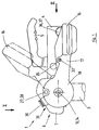
- FIG. 1 shows a trailer coupling (1) for Vehicle trailer. It consists of a clutch housing (4) with an inside clutch mechanism (not shown) and a clutch handle (5).
- the Coupling housing (4) is with the drawbar, the drawbar or the like. Connection part of a vehicle trailer (not shown) connected by means of housing screws (36).
- the Trailer coupling (1) is on the coupling member (2), here preferably a coupling ball, the towing vehicle (not shown) and with the coupling mechanism locked.
- the clutch housing (4) has at the front end a hemispherical dome and clamps together with the Coupling mechanism the coupling ball (2) in Closed position positively.
- the trailer coupling (1) is equipped with a damping device (6) to dampen the rolling movement of the Vehicle trailer equipped.
- the damping device (6) is designed as a friction brake, which preferably separated and arranged in addition to the clutch mechanism is.
- For the clutch housing (4) and the Coupling mechanism and coupling handle (5) can largely on standardized components from conventional Towbars can be used.
- the friction brake (6) has two friction plungers (9, 10) that from the side by means of two actuators (15, 16) and a tensioning element (7) on the coupling member (2) are resiliently pressed.
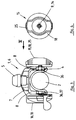
- the axes (14) of each other Coupling member (2) opposite ram (9,10) are aligned and preferably extend transversely to the longitudinal or towing direction of the vehicle trailer.
- the Friction plungers (9,10) are closer in the following described in each case in an actuator (15,16) held, the actuators (15,16) over a screw connection (21) rotatable on the clamping element (7) are stored.
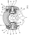
- Figure 5 illustrates in cross section the design of the Friction plunger (9,10). They are of the same design and each consist of a lining carrier (11) with a arranged on the front friction lining (12), the Coupling member (2) is reshaped.
- the topping (11) merges into a thinner shaft (13) on the back a tubular extension (19) of the associated one Actuator (15, 16) is detachably guided.
- At the protruding end of the shaft (13) can be a spring washer or a sealing O-ring for a detachable hold be arranged.
- the friction plungers (9, 10) reach through the clutch housing (4) to the coupling member (2).
- the friction plungers (9, 10) reach through the clutch housing (4) to the coupling member (2).
- the lining carriers (11) and preferably have the corresponding passage openings (20) one circular shape, but can also be designed differently.
- the tensioning element (7) is preferred Embodiment as a substantially U-shaped spring clip trained of the coupling member (2) and the front Grip area of the clutch housing (4).
- the Spring clip (7) is preferably designed as a steel part. Alternatively, it can also be from another suitable one metallic or non-metallic material.
- the Spring action preferably comes from the dimensional stability of the Spring clip (7).
- the spring clip (7) is in the direction of Friction ram axes (14) floating. By side Springs (23) in the area of the friction tappets (9, 10) Spring clip (7) opposite the clutch housing (4) centered.
- the spring clip (7) extends over seen from the side in an arch section over about 90 ° the coupling member (2) and the front Coupling housing (4).
- the spring clip (7) thereby forms an essentially spherical section-shaped hood.
- the click indicator (30) is used for Signaling the correct closed position of the Trailer coupling (1) and is in a known manner trained, e.g. according to DE-GM 88 11 433.
- the bolt protruding outwards through the spring clip (7) Snap indicator (30) is used to guide the spring clip (7) and prevents displacements or swiveling movements of the Spring clip (7) across the clutch housing (4) or around the ram axes (14). This leadership role can also perceive other coupling parts.
- the Through opening in the spring clip (7) is as in Direction of the ram axes (14) extending Elongated hole so that the spring clip on the Snap indicator (30) guided in the direction of Friction ram axes (14) on the clutch housing (4) back and forth can derive.
- the two side bracket arms (8) of the spring bracket (7) are the two actuators (15, 16) via the the aforementioned screw connection (21) and the lugs (19) rotatably guided.
- the screw connection (21) is preferably a self-locking thread.
- On the Approach (19) can also be pulled up a socket (22), which then carries the thread, such as. B. at Actuator (16).
- the Spring bracket (7) with a suitable turn on the Thread openings directly on the lining carrier (11) or indirectly via the correspondingly shaped socket (22) guided.
- the threaded openings in the side arms (8) are aligned with the passage openings (20) in the Coupling housing (4).
- the actuator assigned to the first ram (9) (15) is preferably designed as a feed wheel. It consists of a rotating part (18), of which the aforementioned Approach (19) with the screw connection (21) protrudes. On the rotating part (18) is a handle part (25) on the circumference arranged that as a ring disc with gag-like Handle projections is formed. Between the turned part (18) and the handle part (25) can be a slip clutch (24) be arranged. Until preferably one is reached adjustable torque that takes from operator actuated handle part (25) with the rotating part (18) and slips when the torque limit is exceeded.
- the spring clip (7) has a side in the area of the feed wheel (15) Recess (16) into which the handle part (25) over the Delivery route immersed.
- the immersion depth is a measure of the feed path of the ram (9) and can Markings on the handle part (25) are signaled. If the wear limit has been reached and the ram (9,10) or the friction linings (12) are replaced must, the operator is informed by an appropriate Mark displayed.
- the other actuator (16), the second The friction plunger (19) is assigned as a rotatable one Clamping lever designed. It also consists of one Turned part (18) with the above-mentioned projecting projection (19) and a lever arm (17) with an end handle.
- the rotating part (18) has essentially the shape of a curved one Circular disc.
- the spring clip (7) is on the rotating part (18) facing side, the rotary part (18) with its axially protruding edge also in overlaps the essential circular step approach. Between the rotating part (18) and the spring clip (7) can a spring and / or a seal in the in FIG shown manner. A similar arrangement can also be present on the delivery wheel (15).
- the tensioning lever (16) can be, for example Cover the clamping angle of approx. 60 °.
- Figure 1 shows the Open position with uplifting clamping lever (16) with dashed lines. In the one with solid lines The closed position shown is the clamping lever (16) in essentially horizontal and extends approximately lengthways the pulling or towing direction of the vehicle trailer the clutch housing (4). About the screw movement of the The lever (16) pushes the shoulder (19) the second Friction plunger (10) and presses over the clamping element (7) both friction plungers (9, 10) on the coupling member (2).
- the start and end positions of the application path are determined by a Locking device (27) marked and possibly also limited. In the preferred embodiment, this is as Spring catch formed, a pin in the rotating part (18) (28) is resiliently mounted in the two end positions the swivel path into corresponding lateral openings (29) of the spring clip (7) engages.
- the delivery wheel (15) can be turned further, whereby the two friction plungers (9, 10) more and more to the Coupling member (2) are pressed.
- the spring clip (7) is thereby in the direction of the ram axes (14) spread and unfolding a resilient Restoring force stretched.
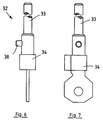
- a locking device (32) is provided. She has one shown in Figures 6 and 7 in more detail Locking pin (33) on a laterally protruding Has bolt (38) and equipped with a lock (34) is. There are two lateral ones in the clutch housing (4) Housing openings (35) through which the locking pin (33) can be inserted. About the lock (34) in Insert position of the bolt (38) are extended, the pulling the locking pin (33) prevented.
- the housing openings (35) are placed so that the Locking pin (33) with its from the clutch housing (4) protruding front end with the in the closed position located clamping lever (16) enters into locking engagement. To do this, he can directly into an opening on the lever arm (17) to grab.
- the front end of the pin can also be connected to the Project the lever arm (17) and prevent it from turning up.
- the housing screws (36) mentioned in the beginning by the Coupling housing (4) and the drawbar that the Screw heads (37) on the clamping lever (16) facing the housing side.
- the brake arm (17) covers the friction brake (6) Screw heads (37).
- the trailer coupling (1) can then no longer be unscrewed and removed from the towing bar.
- the nuts of the housing screws (36) can be to solve.
- the Housing screws (36) but not from the clutch housing (4) can be pulled out.
- the coupling member can be shaped in any way, the relevant parts of the trailer coupling (1) and the friction brake (6) being adapted and changed accordingly.
- the tensioning element (7) does not have to form a separate part, but can also be part of the clutch housing (4).
- the tensioning element (7) can also be designed in a different way and / or can be assigned to the clutch housing in order to build up a resilient tensioning force between the friction rams or the actuating members.
- the friction plungers (9, 10) can be mounted on the clamping element via the screw connection and can then optionally be firmly connected to the actuating members.
- the actuators can also be modified. Instead of rotating parts, it can also be swivel parts or sliding parts with corresponding kinematics. Additional devices such as hydraulic or pneumatic clamps etc. can also be used.
- the locking device can also be used for others Modify towbars with a friction brake and use, e.g. the locking member arranged so and / or with attachments, etc., that it at the same time the actuator of the friction brake and the Coupling mechanism or the clutch handle detected.
- the handles and other parts of the coupling may be or adjust the friction brake accordingly.
Landscapes
- Engineering & Computer Science (AREA)
- Transportation (AREA)
- Mechanical Engineering (AREA)
- Regulating Braking Force (AREA)
Claims (12)
- Procédé d'amortissement du mouvement de roulis de remorques de véhicules au moyen d'un frein à friction (6) sur l'attelage de remorque (1), au moins deux poussoirs à friction (9, 10) montés flottants en vis-à-vis l'un de l'autre étant avancés et pressés élastiquement contre l'organe d'attelage (2) du véhicule de traction, caractérisé en ce que les poussoirs à friction (9, 10) sont avancés individuellement et l'un après l'autre contre l'organe d'attelage (2) par des organes d'actionnement (15, 16) séparés, le mouvement d'avance du premier poussoir à friction (9) amenant les deux poussoirs à friction (9, 10) en contact avec l'organe d'attelage (2) avec enregistrement de l'usure par frottement et le mouvement d'avance du deuxième poussoir à friction (10) ou poussoir à friction supplémentaire s'accompagnant de l'application d'une force de serrage élastique, qui agit entre les poussoirs à friction (9, 10).
- Procédé selon la revendication 1, caractérisé en ce que la force de pression du premier poussoir à friction (9) est limitée.
- Procédé selon la revendication 1 ou 2, caractérisé en ce que le deuxième poussoir à friction (10) ou poussoir à friction supplémentaire est avancé avec une course et une force de serrage constantes.
- Dispositif d'amortissement du mouvement de roulis de remorques de véhicules au moyen d'un frein à friction (6) sur l'attelage de remorque (1), le frein à friction (6) comportant au moins deux poussoirs à friction (9, 10) montés flottants en vis-à-vis l'un de l'autre qui peuvent être avancés et pressés élastiquement contre l'organe d'attelage (2) du véhicule de traction, caractérisé en ce que les poussoirs à friction (9, 10) sont reliés entre eux par un élément de serrage (7) à ressort commun qui est monté flottant par rapport à l'organe d'attelage (2), les poussoirs à friction (9, 10) étant avancés individuellement, comportant des organes d'actionnement (15, 16) séparés et pouvant, dans la position de fermeture, être pressés avec élasticité contre l'organe d'attelage (2) par l'élément de serrage (7).
- Dispositif selon la revendication 4, caractérisé en ce que les poussoirs à friction (9, 10) sont montés sur l'élément de serrage (7).
- Dispositif selon la revendication 4 ou 5, caractérisé en ce que l'élément de serrage (7) est monté flottant au-dessus de l'organe d'attelage (2) dans la direction des axes (14) des poussoirs à friction.
- Dispositif selon la revendication 4, 5 ou 6, caractérisé en ce que l'élément de serrage (7) est réalisé sous la forme d'un étrier à ressort qui surmonte la boíte d'attelage (4) et est guidé transversalement par rapport aux axes (14) de poussoirs à friction.
- Dispositif selon l'une des revendications 4 à 7, caractérisé en ce que les poussoirs à friction (9, 10) sont guidés dans des ouvertures de passage (20) latérales de la boíte d'attelage (4).
- Dispositif selon l'une des revendications 4 à 8, caractérisé en ce que les organes d'actionnement (15, 16) sont montés tournants sur l'élément de serrage (7).
- Dispositif selon la revendication 9, caractérisé en ce que l'un (15) des organes d'actionnement est réalisé sous forme de roue de serrage et l'autre (16) sous la forme d'un levier de serrage.
- Dispositif selon la revendication 9 ou 10, caractérisé en ce que les poussoirs à friction (9, 10) sont tenus dans les organes d'actionnement (15, 16) en prenant appui axialement, les organes d'actionnement (15, 16) étant réglés au moyen d'un assemblage vissé (21) sur l'élément de serrage (7).
- Dispositif selon l'une des revendications 4 à 11, caractérisé en ce que l'un (15) des organes d'actionnement comporte un accouplement à glissement (24).
Applications Claiming Priority (2)
| Application Number | Priority Date | Filing Date | Title |
|---|---|---|---|
| DE4421209A DE4421209C1 (de) | 1994-06-17 | 1994-06-17 | Verfahren und Vorrichtung zum Dämpfen der Schlingerbewegung von Fahrzeuganhängern |
| DE4421209 | 1994-06-17 |
Publications (2)
| Publication Number | Publication Date |
|---|---|
| EP0687583A1 EP0687583A1 (fr) | 1995-12-20 |
| EP0687583B1 true EP0687583B1 (fr) | 1998-07-15 |
Family
ID=6520825
Family Applications (1)
| Application Number | Title | Priority Date | Filing Date |
|---|---|---|---|
| EP95107097A Expired - Lifetime EP0687583B1 (fr) | 1994-06-17 | 1995-05-11 | Procédé et dispositif pour l'amortissement du mouvement oscillatoire de remorques pour véhicule |
Country Status (2)
| Country | Link |
|---|---|
| EP (1) | EP0687583B1 (fr) |
| DE (2) | DE4421209C1 (fr) |
Families Citing this family (7)
| Publication number | Priority date | Publication date | Assignee | Title |
|---|---|---|---|---|
| DE19742707C2 (de) * | 1997-09-26 | 2001-04-26 | Johannes Gubernath | Schlingerdämpfer |
| NL1010010C2 (nl) * | 1998-09-04 | 2000-03-07 | Teun Johan Hugo Leende Sanders | Aanhangwagenkoppeling met slot. |
| DE20116706U1 (de) | 2001-10-11 | 2001-12-06 | Knott GmbH, 83125 Eggstätt | Zugkupplung mit Stabilisierungseinrichtung |
| DE102005031505B4 (de) * | 2005-07-06 | 2010-09-30 | Albe Berndes Gmbh Zugkugelkupplungen | Kugelkopfkupplung mit Bremselementen |
| US7780146B2 (en) * | 2007-09-28 | 2010-08-24 | D B Industries, Inc. | Retrieval assembly |
| DE102009042638A1 (de) | 2009-09-23 | 2010-06-17 | Daimler Ag | Vorrichtung zur Anhängerstabilisierung, Anhänger sowie LKW-Zug |
| DE202018103896U1 (de) * | 2018-07-06 | 2019-10-09 | Alois Kober Gmbh | Anhängerkupplung mit einer Reibungsbremse |
Family Cites Families (7)
| Publication number | Priority date | Publication date | Assignee | Title |
|---|---|---|---|---|
| US2998268A (en) * | 1958-03-27 | 1961-08-29 | Witter Colin Preston | Trailer couplings |
| DE1888887U (de) * | 1963-11-12 | 1964-03-05 | Peka Fahrzeugbau K G | Stabilisierungsvorrichtung fuer kraftfahrzeuganhaenger. |
| GB1573093A (en) * | 1978-05-30 | 1980-08-13 | Taylor F | Stabilising devices for use between a towing vehicle and atrailer vehicle |
| DE3425804C3 (de) * | 1984-07-13 | 1993-11-18 | Westfalia Werke Knoebel | Fahrzeug-Anhängerkupplung mit Reibungsbremse |
| GB8728847D0 (en) * | 1987-12-10 | 1988-01-27 | Ennis C P | Ball joint socket coupling |
| DE3829132A1 (de) * | 1988-08-27 | 1990-03-15 | Kober Ag | Reibungsbremse fuer eine anhaengerkupplung |
| DE8811433U1 (de) * | 1988-09-09 | 1988-10-27 | AL-KO Kober AG, 8871 Kötz | Anhängerkupplung |
-
1994
- 1994-06-17 DE DE4421209A patent/DE4421209C1/de not_active Expired - Fee Related
-
1995
- 1995-05-11 EP EP95107097A patent/EP0687583B1/fr not_active Expired - Lifetime
- 1995-05-11 DE DE59502805T patent/DE59502805D1/de not_active Expired - Lifetime
Also Published As
| Publication number | Publication date |
|---|---|
| DE4421209C1 (de) | 1995-07-27 |
| DE59502805D1 (de) | 1998-08-20 |
| EP0687583A1 (fr) | 1995-12-20 |
Similar Documents
| Publication | Publication Date | Title |
|---|---|---|
| DE10136057C1 (de) | Kniehebelspannvorrichtung | |
| DE3046680A1 (de) | Aufspannvorrichtung fuer ein schneidrad an einer stossmaschine | |
| EP0687583B1 (fr) | Procédé et dispositif pour l'amortissement du mouvement oscillatoire de remorques pour véhicule | |
| DE3524694C2 (fr) | ||
| DE9005050U1 (de) | Kupplungsstange für eine abnehmbare Anhängerkupplung | |
| DE8611037U1 (de) | Scheibenbremse, insbesondere für Kraftfahrzeuge | |
| DE4134405A1 (de) | Vorrichtung zum befestigen eines schneidwerkzeugs an einer schneidmaschine | |
| EP1419320B1 (fr) | Dispositif pour l'actionnement d'un cable | |
| DE3624089C2 (fr) | ||
| DE9412514U1 (de) | Kugelkopf-Anhängerkupplung | |
| DE102010037546A1 (de) | Sicherungs-Spannvorrichtung | |
| DE2749311A1 (de) | Dreipunkthakenkupplung fuer die kupplung eines arbeitsgeraetes mit einem schlepper | |
| DE3829132C2 (fr) | ||
| DE4430492C2 (de) | Positionierzylinder | |
| DE102019116066B4 (de) | Anhängevorrichtung | |
| DE3104728A1 (de) | Befestigungsvorrichtung fuer einen fuehrungsbolzen einer schwimmsattel-teilbelagscheibenbremse | |
| DE3206907C2 (de) | Zangenartiges Werkzeug, insbesondere Universalzange | |
| DE2360942C3 (de) | Selbsttätige Nachstellvorrichtung fur Bremsbacken von Kraftfahrzeugbremsen | |
| DE3425609C2 (fr) | ||
| DE9216760U1 (de) | Markiergerät zum Anbringen von Markierungen an Rohrmänteln | |
| CH656569A5 (de) | Spannvorrichtung zum befestigen eines werkzeughalters an einer werkzeugspindel. | |
| DE2519917B2 (de) | Handbremsventil fuer lastwagen mit anhaenger | |
| DE60002404T2 (de) | Verbessertes handwerkzeug | |
| DE1752751A1 (de) | Schneidkopf fuer nur eine Gewindegroesse | |
| DE202012101466U1 (de) | Rotorsystem für ein Fahrrad, insbesondere Bowdenzugeinhängung für das Rotorsystem |
Legal Events
| Date | Code | Title | Description |
|---|---|---|---|
| PUAI | Public reference made under article 153(3) epc to a published international application that has entered the european phase |
Free format text: ORIGINAL CODE: 0009012 |
|
| AK | Designated contracting states |
Kind code of ref document: A1 Designated state(s): DE FR GB IT NL |
|
| 17P | Request for examination filed |
Effective date: 19960119 |
|
| 17Q | First examination report despatched |
Effective date: 19970430 |
|
| GRAG | Despatch of communication of intention to grant |
Free format text: ORIGINAL CODE: EPIDOS AGRA |
|
| GRAG | Despatch of communication of intention to grant |
Free format text: ORIGINAL CODE: EPIDOS AGRA |
|
| GRAH | Despatch of communication of intention to grant a patent |
Free format text: ORIGINAL CODE: EPIDOS IGRA |
|
| GRAH | Despatch of communication of intention to grant a patent |
Free format text: ORIGINAL CODE: EPIDOS IGRA |
|
| GRAA | (expected) grant |
Free format text: ORIGINAL CODE: 0009210 |
|
| AK | Designated contracting states |
Kind code of ref document: B1 Designated state(s): DE FR GB IT NL |
|
| GBT | Gb: translation of ep patent filed (gb section 77(6)(a)/1977) |
Effective date: 19980716 |
|
| REF | Corresponds to: |
Ref document number: 59502805 Country of ref document: DE Date of ref document: 19980820 |
|
| ET | Fr: translation filed | ||
| PLBE | No opposition filed within time limit |
Free format text: ORIGINAL CODE: 0009261 |
|
| STAA | Information on the status of an ep patent application or granted ep patent |
Free format text: STATUS: NO OPPOSITION FILED WITHIN TIME LIMIT |
|
| 26N | No opposition filed | ||
| REG | Reference to a national code |
Ref country code: GB Ref legal event code: IF02 |
|
| PGFP | Annual fee paid to national office [announced via postgrant information from national office to epo] |
Ref country code: IT Payment date: 20080529 Year of fee payment: 14 |
|
| PGFP | Annual fee paid to national office [announced via postgrant information from national office to epo] |
Ref country code: GB Payment date: 20100329 Year of fee payment: 16 |
|
| PGFP | Annual fee paid to national office [announced via postgrant information from national office to epo] |
Ref country code: NL Payment date: 20100531 Year of fee payment: 16 |
|
| PG25 | Lapsed in a contracting state [announced via postgrant information from national office to epo] |
Ref country code: IT Free format text: LAPSE BECAUSE OF NON-PAYMENT OF DUE FEES Effective date: 20090511 |
|
| REG | Reference to a national code |
Ref country code: NL Ref legal event code: V1 Effective date: 20111201 |
|
| GBPC | Gb: european patent ceased through non-payment of renewal fee |
Effective date: 20110511 |
|
| PG25 | Lapsed in a contracting state [announced via postgrant information from national office to epo] |
Ref country code: NL Free format text: LAPSE BECAUSE OF NON-PAYMENT OF DUE FEES Effective date: 20111201 |
|
| PG25 | Lapsed in a contracting state [announced via postgrant information from national office to epo] |
Ref country code: GB Free format text: LAPSE BECAUSE OF NON-PAYMENT OF DUE FEES Effective date: 20110511 |
|
| PGFP | Annual fee paid to national office [announced via postgrant information from national office to epo] |
Ref country code: DE Payment date: 20140506 Year of fee payment: 20 Ref country code: FR Payment date: 20140422 Year of fee payment: 20 |
|
| REG | Reference to a national code |
Ref country code: DE Ref legal event code: R071 Ref document number: 59502805 Country of ref document: DE |
|
| REG | Reference to a national code |
Ref country code: DE Ref legal event code: R071 Ref document number: 59502805 Country of ref document: DE |