EP0687619A1 - Support de stationnement pour bicyclettes - Google Patents
Support de stationnement pour bicyclettes Download PDFInfo
- Publication number
- EP0687619A1 EP0687619A1 EP95109074A EP95109074A EP0687619A1 EP 0687619 A1 EP0687619 A1 EP 0687619A1 EP 95109074 A EP95109074 A EP 95109074A EP 95109074 A EP95109074 A EP 95109074A EP 0687619 A1 EP0687619 A1 EP 0687619A1
- Authority
- EP
- European Patent Office
- Prior art keywords
- section
- bicycle parking
- parking system
- support leg
- connecting pipe
- Prior art date
- Legal status (The legal status is an assumption and is not a legal conclusion. Google has not performed a legal analysis and makes no representation as to the accuracy of the status listed.)
- Granted
Links
- 239000000463 material Substances 0.000 claims description 27
- 239000002184 metal Substances 0.000 claims description 14
- 229910052751 metal Inorganic materials 0.000 claims description 14
- 238000013459 approach Methods 0.000 claims description 11
- 239000004033 plastic Substances 0.000 claims description 5
- 238000002347 injection Methods 0.000 claims description 3
- 239000007924 injection Substances 0.000 claims description 3
- 239000007769 metal material Substances 0.000 claims description 3
- 230000000295 complement effect Effects 0.000 claims description 2
- 241001212149 Cathetus Species 0.000 claims 1
- 230000006378 damage Effects 0.000 description 9
- XEEYBQQBJWHFJM-UHFFFAOYSA-N Iron Chemical compound [Fe] XEEYBQQBJWHFJM-UHFFFAOYSA-N 0.000 description 6
- 238000013461 design Methods 0.000 description 4
- 238000011161 development Methods 0.000 description 3
- 230000018109 developmental process Effects 0.000 description 3
- 229910052742 iron Inorganic materials 0.000 description 3
- 230000015572 biosynthetic process Effects 0.000 description 2
- 238000004519 manufacturing process Methods 0.000 description 2
- 238000005058 metal casting Methods 0.000 description 2
- 238000012986 modification Methods 0.000 description 2
- 230000004048 modification Effects 0.000 description 2
- 230000002787 reinforcement Effects 0.000 description 2
- 229910000831 Steel Inorganic materials 0.000 description 1
- 238000010521 absorption reaction Methods 0.000 description 1
- 238000005452 bending Methods 0.000 description 1
- 238000006073 displacement reaction Methods 0.000 description 1
- 230000007613 environmental effect Effects 0.000 description 1
- 238000003780 insertion Methods 0.000 description 1
- 230000037431 insertion Effects 0.000 description 1
- 230000013011 mating Effects 0.000 description 1
- 238000004080 punching Methods 0.000 description 1
- 230000003014 reinforcing effect Effects 0.000 description 1
- 230000000284 resting effect Effects 0.000 description 1
- 239000010959 steel Substances 0.000 description 1
- 238000003860 storage Methods 0.000 description 1
- 239000000758 substrate Substances 0.000 description 1
- 230000009182 swimming Effects 0.000 description 1
- 238000012549 training Methods 0.000 description 1
- 238000003466 welding Methods 0.000 description 1
Images


Classifications
-
- B—PERFORMING OPERATIONS; TRANSPORTING
- B62—LAND VEHICLES FOR TRAVELLING OTHERWISE THAN ON RAILS
- B62H—CYCLE STANDS; SUPPORTS OR HOLDERS FOR PARKING OR STORING CYCLES; APPLIANCES PREVENTING OR INDICATING UNAUTHORIZED USE OR THEFT OF CYCLES; LOCKS INTEGRAL WITH CYCLES; DEVICES FOR LEARNING TO RIDE CYCLES
- B62H3/00—Separate supports or holders for parking or storing cycles
- B62H3/04—Separate supports or holders for parking or storing cycles involving forked supports of brackets for holding a wheel
-
- B—PERFORMING OPERATIONS; TRANSPORTING
- B62—LAND VEHICLES FOR TRAVELLING OTHERWISE THAN ON RAILS
- B62H—CYCLE STANDS; SUPPORTS OR HOLDERS FOR PARKING OR STORING CYCLES; APPLIANCES PREVENTING OR INDICATING UNAUTHORIZED USE OR THEFT OF CYCLES; LOCKS INTEGRAL WITH CYCLES; DEVICES FOR LEARNING TO RIDE CYCLES
- B62H3/00—Separate supports or holders for parking or storing cycles
Definitions
- the invention relates to a series of bicycle parking systems consisting of a number of single or double parkers, each of which has a stand which is arranged in a vertical plane and is made of tubular material and which is supported on the floor by the free end of at least one, preferably two, support legs is embedded in the ground, with mutually associated support legs of the stands of adjacent Parkers being connected by horizontal connecting pipe sections, the free ends of which are each fastened to the support legs of one of the Parkers.
- single or double bicycle parkers of the type mentioned at the outset have proven themselves, in which a side bracket is attached to the support leg at a distance from the ground on the metallic stand which is bent from tubular material and which has an insertion space for the front wheel between itself and the support bracket holding bike creates.
- the side brackets are arranged on the opposite sides of the stand so that the bicycles can be inserted from opposite sides into the space between the stand and the side brackets.
- adjacent bicycle parkers are generally designed in such a way that bicycles which can be adjusted in succession are designed alternately in the Parker with the front wheel raised and the front wheel on the ground.
- the bicycle parkers described are practically unchanged, with only the lower ends of the support legs being extended so that the lateral front wheel mounting brackets are lifted off the ground accordingly.
- the invention has for its object to design bicycle parker row systems of the type mentioned so that it is ensured that the bicycles set in them maintain a high level of stability and still be easy on the rim.
- they should be capable of being trained to be particularly resistant to vandalism by a correspondingly stable connection of their parts.
- this object is achieved according to the invention in that in the fastening region of the connecting pipe section with the supporting legs, a connecting element projecting upward in the region of the respective supporting leg above the height of the pipe sections is arranged, which from its highest point is led down from each with an inclined boundary edge to the subsequent connecting pipe sections.
- the connecting element the inclined boundary edges of which form guides for the inserted front wheels of the bicycles to be held in the sense that the bicycles are brought into an inclination in the direction of the stand and thus tilting away in the opposite direction, i.e. away from the associated stand, with certainty avoided, can also serve to additionally reinforce the fastening of the connecting pipe sections and the support legs.
- the connecting element is expediently attached to the connecting pipe sections and, in an advantageous development of the invention, also to the supporting leg.
- the connecting elements are provided in their end regions which lead down to the connecting tube sections, each with an approach which projects upwards over the connecting tube sections and forms a side stop which prevents the front wheel of a set bicycle from slipping away sideways.
- the connecting elements are designed as gusset plates, which have the basic shape of an isosceles triangle, the hypotenuse of which runs essentially at the lower limit of the connecting pipe sections, while the cathets form the obliquely running boundary edges.
- the side stop approaches are then integrally cut on the gusset plate in the area where the cathets meet the hypotenuse.
- the gusset plate can in each case be fastened to the support leg and / or the connecting pipe sections by means of fastening screws, the threaded shafts of the fastening screws being screwed through through openings in the gusset plates into the respective supporting leg or connecting pipe section.
- the through openings in the gusset plate itself can be designed as elongated holes to compensate for manufacturing or assembly inaccuracies.
- connection pipe sections are attached to the associated support leg of the stand by plug-like connection sleeves (DE-GM 90 12 662.9) which are attached to the support leg and fit into the open ends of the connection pipe sections
- the shafts of the fastening screws are expediently made through openings in the gusset plate and screwed through the respective connecting pipe section into a threaded bore in the respective connecting sleeve. It then makes sense to use the same connecting screw to fasten the gusset plate and the connecting pipe section.
- the oblique bounding edges formed by the cathets of the triangular gusset plate and / or the bounding edges of the side stop approaches facing the support leg are expediently deburred and / or chamfered or rounded in order to avoid damage to the rubber of the covers of the front wheel of the wheel to be adjusted.
- strips of the sheet metal material cut in one piece can be folded over from the obliquely running boundary edges forming the cathets of the triangular gusset plate. When the front wheel slides into the intended position inclined to the stand, no sharp edges can then act on the rubber material of the front wheel of the set bicycle.
- An integrally cut strip of the sheet material of the gusset plate can also be folded over in the same way from the boundary edge of the side stop attachment facing the support leg.
- the front wheel of a bicycle to be adjusted If the side bracket embracing the side opposite the stand is provided, the clear distance of the boundary edge of the side stop attachment facing the support leg from the associated support leg is preferably selected to be at least equal to the clear distance between the support leg and the respective side bracket. This ensures that the inclination of the front wheel and thus the set bicycle in the direction of the stand can not be so great that the rim of the front wheel on the side facing away from the stand comes into clamping engagement with the side bracket.
- the connecting elements described above designed as a gusset plate made of metal
- the connecting elements can also be designed as plastic injection molded parts or as metal castings.
- connecting elements in two parts in such a way that they at least partially overlap the connecting area of the respective support leg with the end area of the adjoining connecting pipe section at the front and rear, respectively, and that the front and rear part of the connecting element then be connected to each other in the intended fastening position.
- the interconnected parts of the connecting element can then be designed such that they have a vertical clamping section which laterally encompasses the support leg over a maximum of 180 ° and a horizontal clamping section encompassing the associated connecting pipe section over more than 180 ° from the top, the oblique section Sections forming the boundary edge and the section of the connecting element parts forming the optionally provided side stop projection are each integrally attached to the clamping sections.
- connection of the parts of the connecting element in the intended fastening position can be carried out by screwing or also by latching complementary projections and recesses in the connecting element parts that can be positively engaged with one another.
- a further modified embodiment of the invention can be designed in such a way that the connecting element has an elongated base element which can be fastened in the fastening region of a connecting pipe section with the associated support leg, on the upper side of which, facing away from the connecting pipe section, a section of an elongated metallic profile material is fastened - for example welded on - is which extends obliquely upwards from the support area on the base element from the support leg to the support leg and thus forms the oblique boundary edge with its side facing away from the base element.
- a side stop shoulder can also be provided here, which is formed by arranging a shoulder which is also formed by a section of a metallic profile material and which forms the side stop on the base element side of the fastening region of the oblique profile material section on the base element.
- the profile element section forming the side stop approach can be formed by a series of partial sections, of which the first partial section protrudes upward from the base element, while the subsequent partial section away from the oblique profile element section and the subsequent partial section to the base element folded back or bent and attached to the base element.
- a section of the profile material, which lower end is fastened to the base element, is expediently guided parallel to the support leg and vertically down to the base element.
- a fastening hole for the shaft of a fastening screw or the like which can be fastened in a hole in the support leg can then be fastened in this section of profile material guided parallel to the support leg to the base element.
- the profile material sections of the connecting element are integral parts of an elongated metal profile, which is therefore bent or bent before it is attached to the base element in such a way that the profile material sections are created.
- the base element is expediently formed by a metallic base plate which is curved in the form of a circular section, the radius of the side of the base plate facing the connecting pipe section being approximately equal to the radius of the outer surface of the associated connecting pipe section.
- the circular section-shaped curvature of the cross section of the base plate extends over an angle of a maximum of 180 ° in order to be able to place the connecting element on the connecting pipe section during the assembly without clamping.
- a fastening bore for the shaft of a fastening screw can be provided approximately in the area below the oblique profile material section.
- the position of the mounting hole in the base element is expediently chosen so that it is provided in any case in the associated connecting pipe section Mounting hole is aligned.
- the base element and the connecting pipe section can then be screwed together with a fastening screw with the sleeve that connects the connecting pipe section to the support leg.
- the fastening hole in the base element is then expediently designed as an elongated hole running parallel to the longitudinal central axis of the associated connecting pipe section.
- the metal profile used to form the individual metal profile sections can be designed as a flat, round or tubular profile.
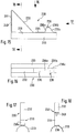
- the bicycle parker system shown in FIGS. 1 and 2, designated in its entirety by 10, has a multiplicity of alternately laterally offset double parkers 12, 12 ', which are held at a predetermined distance from one another by connecting pipe sections 14.
- the double parkers 12 and 12 ' are designed in a known manner so that they each have a U-shaped stand 16 bent from tubular material. These stands 16 are arranged in reverse, ie with the free ends of the two U-legs pointing downward towards the floor in laterally offset parallel vertical planes, the U-legs thus forming support legs 18 which are connected at their upper end by a web section 20 are connected.
- a side bracket 22 is provided on one of the two support legs 16 and extends parallel to the stand 16 at a lateral distance from it, so that the front wheel of a bicycle 24 is adjustable in the space formed between the stand and each side bracket, namely the side brackets 22 are each provided on different support legs 18 of the same stand, so that the bicycles 24 - for reasons of space economy - from opposite sides be set in the space between the side brackets and the stand.
- double parkers 12 and 12 ' are alternately arranged, which differ in that the support legs 18 of their stands 16 have different lengths.
- the side brackets 22 are arranged at such a height that the front wheels of a set vehicle rest on the floor.
- the side brackets 22 are arranged offset in height upwards, and in order to accommodate the front wheels of two-wheelers to be adjusted, a mounting bracket 26 is additionally arranged on both sides of the support legs 18, in which the front wheels are in a position raised from the ground can be set.
- the parts projecting laterally from the frame of the bicycle are offset in height from one another in successive parkers, so that the double parkers 12 and 12 'are moved closer together.
- the front wheels are secured by the mounting brackets 26 against tipping sideways in the lower region and by the side brackets in the upper region of the front wheel.
- brackets corresponding to the mounting brackets 26 are not provided, since in this area the connecting pipe sections 14 connecting the support legs 18 of adjacent Parker are fastened.
- the front wheel When a bicycle is placed in such a double parker 12, the front wheel is thus pushed over the connecting tube section 14 on the adjustment side and is then in the intended position Setting position between the two connecting pipe sections on the substrate. It is conceivable that the set front wheel can be moved laterally on the ground in the contact area and then tilted to one side or the other within the scope of the play given between the stand and the respective side bracket. If this tilting takes place in the direction of the stand, the upper part of the front wheel is leaned against the stand with the tube cover.
- FIG. 3 shows a support leg 18 of the stand 16 of a double parker 12, to which - in the drawing figure on the right side of the stand 18 - a connecting pipe section 14 is fastened in a manner known per se by means of a connecting sleeve 28 at a short distance above the floor, in the direction of arrow 3 in Fig. 2, ie from the inside.
- a connecting element in the form of a gusset plate 30 is arranged, which - as can also be seen in FIG.
- the gusset plate in which the gusset plate is shown separately - has the basic shape of an isosceles triangle, the hypotenuse of which is parallel to the floor at the level of the connecting pipe section 14 runs, while the cathets run from the triangular apex provided above the hypotenuse in the center on the support leg 18 from obliquely downwards and outwards to below the surface line of the connecting tube sections 14 lying at the top in the side view and thus each form an oblique boundary edge 32, which in each case in the space between the stand 16 and a side bracket 22 inserted front wheel inevitably slip in the direction of the lowest point of the boundary edge 32, so that the inserted front wheel and thus the bike overall a tendency to tilt in the direction of the stand 16 is forced.
- the cathets of the gusset plate 30 which form the boundary edges 32 are not led to the hypotenuse, but rather merge into a concave arc which extends into a vertically upwardly extending boundary edge 34 of an extension 36 integrally cut on the actual triangle and projecting above the respective connecting pipe section 14 above transforms.
- the boundary edge 34 thus forms a stop edge of the side stop for a set front wheel forming approach 36. That is, a tilting of the front wheel within the space between the stand 18 and the side bracket 22 is only possible to the extent that the hose cover of the set front wheel on the boundary edge 34th of the side stop approach 36 is present. This ensures that the front wheel cannot come into a tilting position that would endanger its rim.
- the gusset plate is fastened by means of fastening screws (not shown), the threaded shafts of which are at a short distance above the hypotenuse of the gusset plate
- the provided elongated holes 38 are screwed into a mating thread in the connecting pipe section 14 or the connecting sleeve 28 fixing the connecting pipe section 14 to the supporting leg 18.
- the fastening area of the connecting pipe sections 14 on the respective supporting leg 18 is additionally stiffened via the gusset plate 30, specifically in particular when an additional fastening screw is screwed into a threaded hole in the support leg 18 through the elongated hole 40, indicated by dash-dotted lines in FIGS. 3 and 4, in the apex region of the triangular gusset plate 30.
- the gusset plate 30 In addition to the task of inevitably guiding and holding the front wheel of a set bicycle, the gusset plate 30 also takes on the function of an additional reinforcement of the fastening area of connecting pipe sections 14 and support legs 18, so that such a series system 10 also withstand the stresses caused by inadvertently starting motor vehicles or withstand deliberate attempts at damage by individuals (vandalism) much better. Because of this reinforcement function, it can therefore make sense to provide gusset plates 30 not only on the double parkers 12, but also in the connection area of the higher double parkers 12 'with the subsequent connecting pipe sections 14, in which case the side stop approaches 36, which are then inoperative there, can be omitted. For reasons of simplification of the storage and assembly security, however, it can make sense to provide gusset plates of the type described, ie with side stop lugs 36, also in this fastening area.
- the formation of the through-openings for the fastening screws as elongated holes 38 and 40 enables the gusset plates 30 to be installed even if the threaded bores receiving the threaded shafts of the fastening screws are not drilled exactly in the prescribed position.
- the boundary edges 32 and 34 of the gusset plate 30 are deburred by grinding after the gusset plate has been punched out, a rounding or chamfering of the cut edges being recommended in order to avoid cut injuries to the rubber of the hose covers of the front wheel of adjusted bicycles.
- a - not shown in the drawing - design is possible such that in the areas of the boundary edges 32 and 34 with which the tube cover of a set front wheel can come into contact, a strip-shaped tab is cut on the sheet material of the gusset plate 30, which then bent or bent at right angles or even a little more than 90 ° after punching out.
- the gusset plate 30 is additionally stiffened.
- FIGS. 7 to 9 show the connection of a support leg 18 of a stand 16 to a connecting pipe section 14 by means of a somewhat modified gusset plate 30 '. Since the gusset plate 30 'shown separately in FIGS. 7 to 9 largely corresponds to the gusset plate 30 and the same parts are provided with the same reference numerals in the drawing figures, only the modifications of the gusset plate 30' compared to the gusset plate 30 are described below, while for the matching configurations can be referred to the preceding description of the gusset plate 30.
- Fig. 5 it can be seen that the hypotenuse of the triangular gusset plate runs somewhat lower than the lower lateral surface of the connecting pipe section 14 to be fastened, which is due to the fact that an approximately right-angled strip-shaped flange section 42 is attached to this hypotenuse below each cathete between which only the area of the support leg 18 is recessed.
- the folded flange sections 42 therefore lie on the underside of the connecting pipe sections 14 to be fastened in each case to the support leg 18, and the elongated holes 38 with which the gusset plate 30 'is fastened to the connecting pipe sections are accordingly also provided in these flange sections 42.
- the gusset plate 30 ′ is additionally stiffened again by the flange sections 42 and the position of the fastening screws on the underside of the connecting pipe sections 14 makes manipulation of the fastening screws difficult in such a way that the gusset plates are removed.
- FIGS. 10 to 14 An alternative to the gusset plates 30 and 30 'described above in connection with FIGS. 3 and 4 and 5 to 9 is shown in FIGS. 10 to 14.
- the connecting element 130 which takes the place of these gusset plates is, in the case shown, a plastic injection-molded part produced from two parts 130a, 130b, but in a similar configuration, production from metal casting is also conceivable.
- the connecting element 130 or the connecting element parts 130a, 130b is or are also basically triangular, but here an embodiment is shown which can also be used in a row system on the terminal bicycle parker, ie in which case only one side of a support leg 18 is used Connection pipe section 14 is attached. If a connecting pipe section 14 is attached to the support leg 18 on both sides on opposite sides, there is also a second connecting element 130 in a position symmetrically mirrored around the left vertical edge.
- the connecting element 130 has the shape of a right-angled triangle, the left vertical boundary of which is formed by a clamping section 131 which laterally encompasses the associated support leg 18, that is to say in horizontal section over an arc of up to 180 ° extends, wherein the inner radius of the clamping portion 131 is equal to the outer radius of the support leg 18.
- the clamping section 131 in turn then consists of clamping section parts 131a and 131b, which are each part of the connecting element parts 130a and 130b.
- a clamping section 133 is integrally formed on the lower horizontal boundary of the connecting element 130, which clampingly encompasses the associated connecting pipe section 14, to a large extent completely, i.e. the clamping section 133 extends over - almost - 360 °.
- Each clamping section part 133a or 133b thus covers an arc of - almost - 180 °.
- An integrally molded straight rib 132 which in turn is composed of two rib parts 132a and 132b, runs obliquely downward from the upper end of the clamping section 131 into the region of the end of the clamping section 131.
- the top of this rib forms the oblique boundary edge on which the front wheel of a bicycle to be adjusted slides, so that the bicycle assumes the position inclined to the stand 16.
- the space enclosed between the clamping sections 131, 133 and the oblique rib 132 is not open, but is closed by a thinner wall 135, which are formed by two superposed wall parts 135a, 135b half the wall thickness.
- the connecting element parts 130a, 130b are connected to the connecting element 130 by screwing the wall parts 135a, 135b with fastening screws (not shown).
- two circular reinforcing eyes 137a, 137b protruding from the outer sides of the walls 135a, 135b are provided for this purpose, through which holes 138 pass, through which the threaded shafts of the fastening screws are passed.
- connecting the parts 130a, 130b are also conceivable, in particular when producing the connecting elements from plastic.
- push-button-like latching elements can be provided in the adjoining surfaces of the parts 130a, 130b of the connecting element, which simply clip the parts 130a, 130b of the connecting element 130 from the front and back of the connecting area of a support leg 18 with an associated connecting pipe section 14 enable.
- FIGS. 10 and 14 each show an opening 139 provided partly in the wall 135 and partly in the clamping section 133, which serves to receive the head of a fastening screw projecting upwards from the connecting pipe section 14, with which the pipe section 14 is attached to the support leg 18 via a connecting sleeve.
- the head of the fastening screw projecting into the opening 139 simultaneously secures the connecting element 130 in the intended fastening position against displacements in the longitudinal direction of the respective connecting pipe section 14.
- FIGS. 15 to 18 an embodiment of a modified connecting element, designated in its entirety with 230, is shown, which is practically composed of two parts, namely an elongated base element 233, which is designed as an elongated base plate in cross-section corresponding to the outer diameter of the connecting pipe sections 14, which is in the connection area of a connecting pipe section 14 with a support leg 18 can be placed on the connecting pipe section, on which a component made of an elongated metal profile, in the illustrated case a flat iron, is placed by folding or bending into a series of metal profile sections and is fastened, this fastening either by welding individual sections resting on the upper side of the base element or by other conventional connecting means, such as riveting, screwing or the like. can be done.
- an elongated base element 233 which is designed as an elongated base plate in cross-section corresponding to the outer diameter of the connecting pipe sections 14, which is in the connection area of a connecting pipe section 14 with a support leg 18 can be placed on the connecting pipe section, on which
- FIG. 15 it can be seen that the obliquely running and the front wheel of a two-wheeler to be inserted into a Parker is forced into the desired oblique boundary edge by the upper side of a section 232 of the metal profile, the one end of which - on the right in FIG an angled intermediate section 235 fastened to the base part 233 passes over, while from its other end, which is guided obliquely upwards to the support leg, a section 231, which runs parallel to the support leg down to the base element 233 and is fastened there again, is attached.
- the profile material section forming the side stop projection 236 is integrally attached to the intermediate section 235 and is composed of sections, of which the section 236a is bent upwards from the intermediate section 235, the subsequent subsection 236b roughly folded back into the horizontal position and the next subsection 236c then folded back obliquely down to the base element 233 and fastened to the base element.
- a fastening hole 240 which is then again expediently designed as an elongated hole, can additionally be provided in the profile material section 231.
- the metal profile used for the formation of the metal profile sections is a flat iron. It can be seen that instead of such a flat iron, other metal profiles, for example round steel or tubular profiles, can also be used.
- Such connecting elements are also conceivable in such a way that instead of gusset plates, correspondingly curved metal profiles on the support legs 18 on the one hand and the connecting pipe sections 14 on the other hand are fastened directly - ie without a support element corresponding to the base element 233 - only care being taken in each case, that the connecting elements must have the inclined boundary edge influencing the tilting of a front wheel set in the Parker in the direction of the stand 16, and that in a suitable manner Distance from the support leg comes a side stop approach with a boundary edge upwards, which prevents the front wheel from tipping too much.
Landscapes
- Engineering & Computer Science (AREA)
- Mechanical Engineering (AREA)
- Refuge Islands, Traffic Blockers, Or Guard Fence (AREA)
- Fencing (AREA)
- Motorcycle And Bicycle Frame (AREA)
Applications Claiming Priority (4)
| Application Number | Priority Date | Filing Date | Title |
|---|---|---|---|
| DE9409746U | 1994-06-19 | ||
| DE9409746U DE9409746U1 (de) | 1994-06-19 | 1994-06-19 | Fahrradparker-Reihenanlage |
| DE4430170A DE4430170C2 (de) | 1994-06-19 | 1994-08-25 | Fahrradparker-Reihenanlage |
| DE4430170 | 1994-08-25 |
Publications (2)
| Publication Number | Publication Date |
|---|---|
| EP0687619A1 true EP0687619A1 (fr) | 1995-12-20 |
| EP0687619B1 EP0687619B1 (fr) | 1998-03-25 |
Family
ID=25939513
Family Applications (1)
| Application Number | Title | Priority Date | Filing Date |
|---|---|---|---|
| EP95109074A Expired - Lifetime EP0687619B1 (fr) | 1994-06-19 | 1995-06-13 | Support de stationnement pour bicyclettes |
Country Status (2)
| Country | Link |
|---|---|
| EP (1) | EP0687619B1 (fr) |
| AT (1) | ATE164358T1 (fr) |
Cited By (2)
| Publication number | Priority date | Publication date | Assignee | Title |
|---|---|---|---|---|
| FR2756539A1 (fr) * | 1996-12-02 | 1998-06-05 | Fort Maurice Francois | Dispositif antivol support de bicyclettes |
| FR2758518A1 (fr) * | 1997-01-20 | 1998-07-24 | Cousin Jean Pierre Joseph | Dispositif antivol de stationnement pour cycles et cyclomoteurs |
Citations (5)
| Publication number | Priority date | Publication date | Assignee | Title |
|---|---|---|---|---|
| DE8715865U1 (de) | 1987-12-01 | 1988-01-21 | Groebe Feinstahlbau KG, 6525 Westhofen | Vorrichtung zum Einstellen von Zweirädern, wie Fahrrädern, Motorfahrrädern, Kleinkrafträdern o. dgl. |
| DE8801595U1 (de) * | 1988-02-09 | 1988-03-31 | FRIESON Handelsgesellschaft für Metall- und Kunststoffprodukte mbH & Co KG, 5909 Burbach | Fahrradständer |
| DE9006455U1 (de) * | 1990-06-08 | 1990-08-16 | Koch, Arnim, 3500 Kassel | Kombinations-Fahrradständer |
| DE9012662U1 (de) | 1990-09-05 | 1990-11-08 | Orion Bausysteme GmbH, 6083 Biebesheim | Rohr-Verbindung |
| DE9404105U1 (de) * | 1994-03-11 | 1994-05-05 | ORION Bausysteme GmbH, 64584 Biebesheim | Fahrradparker-Reihenanlage sowie Fundament- und Beschwerungspoller hierfür |
-
1995
- 1995-06-13 AT AT95109074T patent/ATE164358T1/de not_active IP Right Cessation
- 1995-06-13 EP EP95109074A patent/EP0687619B1/fr not_active Expired - Lifetime
Patent Citations (5)
| Publication number | Priority date | Publication date | Assignee | Title |
|---|---|---|---|---|
| DE8715865U1 (de) | 1987-12-01 | 1988-01-21 | Groebe Feinstahlbau KG, 6525 Westhofen | Vorrichtung zum Einstellen von Zweirädern, wie Fahrrädern, Motorfahrrädern, Kleinkrafträdern o. dgl. |
| DE8801595U1 (de) * | 1988-02-09 | 1988-03-31 | FRIESON Handelsgesellschaft für Metall- und Kunststoffprodukte mbH & Co KG, 5909 Burbach | Fahrradständer |
| DE9006455U1 (de) * | 1990-06-08 | 1990-08-16 | Koch, Arnim, 3500 Kassel | Kombinations-Fahrradständer |
| DE9012662U1 (de) | 1990-09-05 | 1990-11-08 | Orion Bausysteme GmbH, 6083 Biebesheim | Rohr-Verbindung |
| DE9404105U1 (de) * | 1994-03-11 | 1994-05-05 | ORION Bausysteme GmbH, 64584 Biebesheim | Fahrradparker-Reihenanlage sowie Fundament- und Beschwerungspoller hierfür |
Cited By (2)
| Publication number | Priority date | Publication date | Assignee | Title |
|---|---|---|---|---|
| FR2756539A1 (fr) * | 1996-12-02 | 1998-06-05 | Fort Maurice Francois | Dispositif antivol support de bicyclettes |
| FR2758518A1 (fr) * | 1997-01-20 | 1998-07-24 | Cousin Jean Pierre Joseph | Dispositif antivol de stationnement pour cycles et cyclomoteurs |
Also Published As
| Publication number | Publication date |
|---|---|
| EP0687619B1 (fr) | 1998-03-25 |
| ATE164358T1 (de) | 1998-04-15 |
Similar Documents
| Publication | Publication Date | Title |
|---|---|---|
| DE60129182T2 (de) | Modularer Zaun | |
| EP0945564A1 (fr) | Système de table coffrante | |
| EP0716803B1 (fr) | Elément de construction pour la fabrication de bordures et limites dans les jardins et espaces verts | |
| DE602005004790T2 (de) | Strassenleitplanke | |
| EP0220395A1 (fr) | Support de bicyclettes | |
| DE69932267T2 (de) | Zaun mit senkrechten Elementen | |
| DE202004000404U1 (de) | Transportwagen für Gegenstände, insbesondere Reinigungsutensilien | |
| DE2850763A1 (de) | Staender fuer fahrraeder, fahrraeder mit hilfsmotor und motorraeder | |
| DE2908284C2 (de) | Schaltafel für Betonwände | |
| DE4430170C2 (de) | Fahrradparker-Reihenanlage | |
| EP0687619B1 (fr) | Support de stationnement pour bicyclettes | |
| DE19537078C2 (de) | Vorrichtung zum Abstellen eines auf seinen Laufrädern stehenden Fahrrads | |
| DE2949541C2 (de) | Bakenständer | |
| DE7818280U1 (de) | Bausatz fuer schutzgitter zu begrenzungs- und sicherungszwecken, insbesondere fuer schulbushaltestellen | |
| DE4403438A1 (de) | Leitwand für Kraftfahrzeuge | |
| DE9301629U1 (de) | Schwimmbadüberdachung aus mehreren auf Laufschienen verschiebbaren, bogenförmig gewölbten Teilschalen | |
| CH691801A5 (de) | Fahrradständer. | |
| DE29712442U1 (de) | Mobile Absperrvorrichtung | |
| DE4314677A1 (de) | Zweiradparkanlage | |
| DE29513037U1 (de) | Trägersystem | |
| DE9308960U1 (de) | Zweiradständer, insbesondere für Fahrräder | |
| EP0629544B1 (fr) | Support de stationnement pour véhicules à deux roues, en particulier pour bicyclettes | |
| DE19629893A1 (de) | Befahrbare Abdeckung | |
| DE4345134A1 (de) | Überdachung, insbesondere Personenkraftwagenüberdachung | |
| DE102022115390A1 (de) | Schrankensystem zur Verwendung von Wege- oder Durchfahrtssperrungen |
Legal Events
| Date | Code | Title | Description |
|---|---|---|---|
| PUAI | Public reference made under article 153(3) epc to a published international application that has entered the european phase |
Free format text: ORIGINAL CODE: 0009012 |
|
| AK | Designated contracting states |
Kind code of ref document: A1 Designated state(s): AT CH DK FR LI NL |
|
| 17P | Request for examination filed |
Effective date: 19960320 |
|
| GRAG | Despatch of communication of intention to grant |
Free format text: ORIGINAL CODE: EPIDOS AGRA |
|
| GRAG | Despatch of communication of intention to grant |
Free format text: ORIGINAL CODE: EPIDOS AGRA |
|
| GRAH | Despatch of communication of intention to grant a patent |
Free format text: ORIGINAL CODE: EPIDOS IGRA |
|
| 17Q | First examination report despatched |
Effective date: 19970904 |
|
| GRAH | Despatch of communication of intention to grant a patent |
Free format text: ORIGINAL CODE: EPIDOS IGRA |
|
| GRAA | (expected) grant |
Free format text: ORIGINAL CODE: 0009210 |
|
| AK | Designated contracting states |
Kind code of ref document: B1 Designated state(s): AT CH DK FR LI NL |
|
| PG25 | Lapsed in a contracting state [announced via postgrant information from national office to epo] |
Ref country code: NL Free format text: LAPSE BECAUSE OF FAILURE TO SUBMIT A TRANSLATION OF THE DESCRIPTION OR TO PAY THE FEE WITHIN THE PRESCRIBED TIME-LIMIT Effective date: 19980325 Ref country code: FR Free format text: LAPSE BECAUSE OF FAILURE TO SUBMIT A TRANSLATION OF THE DESCRIPTION OR TO PAY THE FEE WITHIN THE PRESCRIBED TIME-LIMIT Effective date: 19980325 |
|
| REF | Corresponds to: |
Ref document number: 164358 Country of ref document: AT Date of ref document: 19980415 Kind code of ref document: T |
|
| REG | Reference to a national code |
Ref country code: CH Ref legal event code: EP |
|
| PG25 | Lapsed in a contracting state [announced via postgrant information from national office to epo] |
Ref country code: AT Free format text: LAPSE BECAUSE OF NON-PAYMENT OF DUE FEES Effective date: 19980613 |
|
| PG25 | Lapsed in a contracting state [announced via postgrant information from national office to epo] |
Ref country code: DK Free format text: LAPSE BECAUSE OF FAILURE TO SUBMIT A TRANSLATION OF THE DESCRIPTION OR TO PAY THE FEE WITHIN THE PRESCRIBED TIME-LIMIT Effective date: 19980625 |
|
| EN | Fr: translation not filed | ||
| NLV1 | Nl: lapsed or annulled due to failure to fulfill the requirements of art. 29p and 29m of the patents act | ||
| PLBE | No opposition filed within time limit |
Free format text: ORIGINAL CODE: 0009261 |
|
| STAA | Information on the status of an ep patent application or granted ep patent |
Free format text: STATUS: NO OPPOSITION FILED WITHIN TIME LIMIT |
|
| 26N | No opposition filed | ||
| PG25 | Lapsed in a contracting state [announced via postgrant information from national office to epo] |
Ref country code: LI Free format text: LAPSE BECAUSE OF NON-PAYMENT OF DUE FEES Effective date: 19990630 Ref country code: CH Free format text: LAPSE BECAUSE OF NON-PAYMENT OF DUE FEES Effective date: 19990630 |
|
| REG | Reference to a national code |
Ref country code: CH Ref legal event code: PL |