EP0687619B1 - Fahrradparker-Reihenanlage - Google Patents
Fahrradparker-Reihenanlage Download PDFInfo
- Publication number
- EP0687619B1 EP0687619B1 EP95109074A EP95109074A EP0687619B1 EP 0687619 B1 EP0687619 B1 EP 0687619B1 EP 95109074 A EP95109074 A EP 95109074A EP 95109074 A EP95109074 A EP 95109074A EP 0687619 B1 EP0687619 B1 EP 0687619B1
- Authority
- EP
- European Patent Office
- Prior art keywords
- support
- row
- section
- parking bicycles
- connecting tube
- Prior art date
- Legal status (The legal status is an assumption and is not a legal conclusion. Google has not performed a legal analysis and makes no representation as to the accuracy of the status listed.)
- Expired - Lifetime
Links
- 239000000463 material Substances 0.000 claims description 29
- 239000002184 metal Substances 0.000 claims description 14
- 229910052751 metal Inorganic materials 0.000 claims description 14
- 238000002347 injection Methods 0.000 claims description 4
- 239000007924 injection Substances 0.000 claims description 4
- 230000000295 complement effect Effects 0.000 claims description 2
- 238000005058 metal casting Methods 0.000 claims description 2
- 239000002991 molded plastic Substances 0.000 claims 1
- 238000013459 approach Methods 0.000 description 16
- 230000006378 damage Effects 0.000 description 9
- XEEYBQQBJWHFJM-UHFFFAOYSA-N Iron Chemical compound [Fe] XEEYBQQBJWHFJM-UHFFFAOYSA-N 0.000 description 6
- 239000004033 plastic Substances 0.000 description 4
- 230000015572 biosynthetic process Effects 0.000 description 3
- 238000013461 design Methods 0.000 description 3
- 238000011161 development Methods 0.000 description 3
- 230000018109 developmental process Effects 0.000 description 3
- 229910052742 iron Inorganic materials 0.000 description 3
- 238000005452 bending Methods 0.000 description 2
- 238000004519 manufacturing process Methods 0.000 description 2
- 238000012986 modification Methods 0.000 description 2
- 230000004048 modification Effects 0.000 description 2
- 238000004080 punching Methods 0.000 description 2
- 238000003860 storage Methods 0.000 description 2
- 241001212149 Cathetus Species 0.000 description 1
- 229910000831 Steel Inorganic materials 0.000 description 1
- 238000010521 absorption reaction Methods 0.000 description 1
- 230000003321 amplification Effects 0.000 description 1
- 238000005520 cutting process Methods 0.000 description 1
- 230000007613 environmental effect Effects 0.000 description 1
- 230000013011 mating Effects 0.000 description 1
- 239000007769 metal material Substances 0.000 description 1
- 238000003199 nucleic acid amplification method Methods 0.000 description 1
- 230000003449 preventive effect Effects 0.000 description 1
- 230000002787 reinforcement Effects 0.000 description 1
- 230000003014 reinforcing effect Effects 0.000 description 1
- 239000010959 steel Substances 0.000 description 1
- 230000009182 swimming Effects 0.000 description 1
- 238000012549 training Methods 0.000 description 1
- 238000003466 welding Methods 0.000 description 1
Images



Classifications
-
- B—PERFORMING OPERATIONS; TRANSPORTING
- B62—LAND VEHICLES FOR TRAVELLING OTHERWISE THAN ON RAILS
- B62H—CYCLE STANDS; SUPPORTS OR HOLDERS FOR PARKING OR STORING CYCLES; APPLIANCES PREVENTING OR INDICATING UNAUTHORIZED USE OR THEFT OF CYCLES; LOCKS INTEGRAL WITH CYCLES; DEVICES FOR LEARNING TO RIDE CYCLES
- B62H3/00—Separate supports or holders for parking or storing cycles
- B62H3/04—Separate supports or holders for parking or storing cycles involving forked supports of brackets for holding a wheel
-
- B—PERFORMING OPERATIONS; TRANSPORTING
- B62—LAND VEHICLES FOR TRAVELLING OTHERWISE THAN ON RAILS
- B62H—CYCLE STANDS; SUPPORTS OR HOLDERS FOR PARKING OR STORING CYCLES; APPLIANCES PREVENTING OR INDICATING UNAUTHORIZED USE OR THEFT OF CYCLES; LOCKS INTEGRAL WITH CYCLES; DEVICES FOR LEARNING TO RIDE CYCLES
- B62H3/00—Separate supports or holders for parking or storing cycles
Definitions
- the invention relates to a series of bicycle parking facilities a number of single or double parkers, each one arranged in a vertical plane, made of pipe material have curved stand that matches the free End of at least one, preferably two support legs is supported on the floor or embedded in the floor, with mutually associated support leg of the stand adjacent Parker through horizontal connecting pipe sections are connected, the free ends of each on Support legs of one of the parkers are attached.
- Bicycles are coming in more recent times - also due to the increased Environmental awareness - increasingly back in Use as individual transportation and means of transportation for Shopping in cities. Accordingly, in the inner city Area by the communities or even the interested Business opportunities for bicycles will. Also at train stations (park and ride stations), swimming pools, leisure centers, sports facilities, schools, Universities etc. are increasingly becoming storage facilities needed for bikes where the bikes protected against damage and secure against theft can then be set.
- the invention has for its object, bicycle parking systems of the type mentioned at the beginning that it is ensured that the bicycles placed in it maintain a high level of stability and still protect the rims can be used. Beyond that them through a correspondingly stable connection of their parts can be trained to be particularly resistant to vandalism be.
- this object is achieved according to the invention solved that in the fastening area of the connecting pipe section with the support legs in the area of each Support leg over the height of the pipe sections
- Above connecting element is arranged, which from its highest point with an oblique one running boundary edge to the subsequent connecting pipe sections is brought down.
- the connecting element whose sloping boundary edges guides for the inserted front wheels of the to be held Form bicycles in the sense that the bicycles are in one Can be brought towards the upright and such a tipping away in the opposite direction, i.e. from assigned stand away, is avoided with certainty can also be used to reinforce the attachment of the Connection pipe sections and the support leg serve.
- the connecting element is expedient on the connecting pipe sections and in an advantageous development of the invention then also attached to the support leg.
- the Fasteners in their to the connecting pipe sections descended end areas with one over each the connecting pipe sections protruding upwards, one the sideways slipping of the front wheel of a set one Preventive side stop forming bicycle Approach.
- the connecting elements are in a preferred further development of the invention designed as gusset plates, which the have the basic shape of an isosceles triangle, whose hypotenuse is essentially at the lower limit the connecting pipe sections runs while the cathets form the oblique boundary edges.
- the side stop approaches are then in the area of The catheters meet with the hypotenuse integral cut on the gusset plate.
- the gusset plate can be attached using fastening screws on the support leg and / or the connecting pipe sections be fastened, the threaded shafts of the fastening screws through openings in the gusset plates through into the respective support leg or connecting pipe section are screwed in.
- the through openings in the gusset plate itself can - for Compensation for manufacturing or assembly inaccuracies - be designed as elongated holes.
- the triangles of the triangular gusset plate can be used forming oblique boundary edges strips of sheet metal material cut in one piece, folded over be. When the front wheel slides into the intended then no inclined position sharp edges on the rubber material of the front wheel set bicycle.
- the side stop approach can be made in one piece in the same way cut strips of the sheet material of the Gusset plate must be folded.
- the clear distance of the Support leg facing boundary edge of the side stop approach preferably from the associated support leg at least equal to the clear distance between the support leg and the respective side bracket selected. So that is ensured that the inclination of the front wheel and thus of the set bicycle towards the stand can become so large that the rim of the front wheel on the side facing away from the stand in clamping engagement with the side bracket is coming.
- Metal-formed fasteners can be the fasteners also as plastic injection molded parts or as Metal castings can be formed.
- connection area of the respective support leg with the end region of the subsequent one Connection pipe section at least partially overlap at the front or rear, and that the front and back part of the connecting element then in the intended mounting position be connected to each other.
- the interconnected parts of the connecting element can then be designed so that they have a vertical, grasp the support leg laterally over a maximum of 180 ° and a horizontal the associated connecting pipe section encompassing more than 180 ° from the top
- Have clamping section which is the oblique Boundary edge forming sections and the where appropriate provided side stop approach-forming section of the connecting element parts each integrally the clamping sections are attached.
- connection of the parts of the connecting element in the intended mounting position can be screwed or also by interlocking with each other mating complementary tabs and recesses in the connecting element parts.
- a further modified embodiment of the invention can be designed so that the connecting element each in the fastening area of a connecting pipe section attachable with the associated support leg has elongated base member, on the connecting pipe portion facing away a section an elongated metallic profile material attached - welded on for example - which of its fastening area removed from the support leg the base element from obliquely upwards to the support leg runs and so with its facing away from the base element Side forms the oblique boundary edge.
- a side stop approach can also be used here be provided, which is formed in that on the side of the fastening area of the fastening side facing away from the support leg sloping profile material section on the Base element also from a section of a metallic Profile material formed, forming the side stop Approach is arranged.
- the profile element section forming the side stop approach can be formed by a number of sections be, of which the first section from the base element advancing upward while the subsequent Section in the direction of the inclined profile element section away and the subsequent subsection folded back to the base element or bent and on the base element is attached.
- the inclined Boundary edge forming profile material section is appropriate a parallel to the support leg perpendicular down to the base element Profile material set, the lower end on the Base element is attached.
- the profile material sections of the fastener are integral parts in a preferred embodiment of the invention an elongated metal profile, which is in front of it Fastening on the base element so bent or bent is that the profile material sections are created.
- the cross section of the base element is expedient Circular segmented arched metal footplate formed, the radius of the connecting pipe section facing side of the footplate about the same the radius of the outer surface of the associated connecting pipe section is selected.
- the curved section the cross section of the footplate extends over an angle of maximum 180 ° around the connecting element when mounting without clamping on the connecting pipe section to be able to put on.
- the base element on the connecting pipe section can be in the area below the sloping Section material section approximately in the middle of a mounting hole provided for the shaft of a fastening screw be.
- the location of the mounting hole in the Base element appropriately chosen so that it with an im assigned connection pipe section provided anyway Mounting hole is aligned.
- Base element and connecting pipe section can then be used together with a fastening screw with which the connection of the connecting pipe section screwed to the socket producing the support leg will.
- the mounting hole in the base element is used for compensation of possible inaccuracies then expediently as parallel to the longitudinal central axis of the associated connecting pipe section running elongated hole formed.
- Metal profile can be used as a flat, round or tubular profile be trained.
- the one shown in Figures 1 and 2 in its entirety 10 designated bicycle parker row system has one Large number of alternately arranged laterally offset Double parking 12, 12 'on by connecting pipe sections 14 held at a predetermined distance from each other are.
- This stand 16 are in reverse, i.e. with the free ends of the two U-leg pointing down to the floor in the side position mutually offset parallel vertical planes arranged, the U-legs thus forming support legs 18, at its upper end by a web section 20 are connected.
- the stand 16 On the opposite side of the stand 16 is in each case one of the two support legs 16 attached side bracket 22 provided, which is in lateral distance from the stand 16 parallel to this, so that in between the stand and each side bracket formed space the front wheel of a bicycle 24 is adjustable, namely the side bracket 22nd each on different support legs 18 of the same Stand provided so that the bicycles 24 - for reasons of space economy - from opposite sides in the Clearance between the side brackets and the stand set will.
- double parkers 12 and 12 ' In the row system 10 are double parkers 12 and 12 'arranged, which differ in that the Support leg 18 of their stand 16 different lengths to have.
- the side bracket 22 In the double parkers 12 with a lower stand 16 the side bracket 22 are arranged at such a height that the Front wheels of a set vehicle on the floor rest.
- the side brackets 22, on the other hand are arranged offset in height upwards, and to accommodate the front wheels to be adjusted
- Two-wheelers is also on both sides of the support legs 18 each have a holding bracket 26 arranged in which the front wheels in a position off the ground can be set.
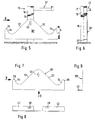
- Figure 3 shows a support leg 18 of the stand 16 Doppelparkers 12, on which - in the drawing figure the right side of the stand 18 - in known per se Way by means of a connecting sleeve 28 at a short distance
- a connecting pipe section 14 is fastened above the floor in the direction of arrow 3 in Fig. 2, i.e. from the inside.
- a connecting element arranged in the form of a gusset plate 30, the - As can also be seen from Fig.
- gusset plate in which the gusset plate is shown separately - the basic form of an isosceles triangle, its hypotenuse parallel to the floor at the level of the connecting pipe section 14 runs while the cathetus runs from the one above the hypotenuse triangle vertex provided in the center of the support leg 18 from diagonally downwards and outwards to below the in the side view above the surface line of the connecting pipe sections 14 run and thus one form oblique boundary edge 32, each one in the space between the stand 16 and a side bracket 22 inserted front wheel inevitably in the direction of the lowest point of the boundary edge 32 slip leave so that the inserted front wheel and thus the Bicycle overall has a tendency to tilt towards the Stand 16 is forced.
- the boundary edges 32 forming cathets of the gusset plate 30 are not up to Hypotenuse led, but go into a concave arc above, into a boundary edge running vertically upwards 34 of an integrally cut on the actual triangle, the respective connecting pipe section 14 approach 36 above.
- the boundary edge 34 thus forms a stop edge of one side stop for a set front wheel forming approach 36. tilting of the front wheel within the space between the stand 18 and the side bracket 22 is only possible so far that the hose cover of the set Front wheel on the boundary edge 34 of the side stop approach 36 is present. This ensures that the front wheel is not in a risk to its rim Tilt position can come.
- the gusset plate is attached by - not shown - Fastening screws, the threaded shafts through at a short distance above the hypotenuse of the gusset plate provided elongated holes 38 into a counter thread in the connecting pipe section 14 or the connecting pipe section 14 attached to the support leg 18
- Connection sleeve 28 are screwed in Fastening area of the connecting pipe sections 14 on respective support leg 18 via the gusset plate 30 additionally stiffened, especially when additional a fastening screw by the in FIGS. 3 and 4 dash-dotted lines, in the apex area of the triangular Gusset plate 30 provided slot 40 in a Threaded hole is screwed into the support leg 18.
- the gusset plate 30 In addition to the task of inevitable guidance and mounting of the front wheel of a set bicycle the gusset plate 30 also functions as an additional one Reinforcement of the fastening area of connecting pipe sections 14 and support legs 18 so that such a series system 10 also the stresses by accidentally starting motor vehicles or deliberate Attempted damage by individuals (vandalism) withstand much better. Because of this amplification function it can therefore make sense to use gusset plates 30 not only on the double parkers 12, but also in the Connection area of the higher double parkers 12 'with the subsequent ones To provide connecting pipe sections 14 the side stop approaches that are then inoperative there 36 can be omitted. For the sake of simplifying the Warehousing and assembly security can, however make sense, even in this fastening area Gusset plates of the type described, i.e. with side stop approaches 36 to provide.
- the boundary edges 32 and 34 of the gusset plate 30 are deburred by grinding after punching out the gusset plate, a rounding or chamfering of the Cutting edges can recommend to avoid cut injuries Rubber of the hose covers of the front wheel from set To avoid bicycles.
- a rounding or chamfering of the Cutting edges can recommend to avoid cut injuries Rubber of the hose covers of the front wheel from set To avoid bicycles.
- there is also an - in the drawing, not shown - configuration such possible that in the areas of the boundary edges 32 and 34, with which the tube cover of a set front wheel can come into contact with the sheet material of the gusset plate 30 a strip-shaped rag is cut, which is then rectangular or even around after punching out is bent or bent a little more than 90 °. Thereby not only the respective boundary edge 32 or 34 disarmed, but the gusset plate 30 additionally stiffened.
- FIG. 5 and 6 is the connection of a support leg 18 of a stand 16 with a connecting pipe section 14 shown by means of a somewhat modified gusset plate 30 '. Since the gusset plate shown separately in FIGS. 7 to 9 30 'largely corresponds to the gusset plate 30 and in the Drawing figures same parts with the same reference numerals are provided below, only those compared to the Gusset plate 30 made modifications of the gusset plate 30 'described while for the matching configurations to the previous description of the gusset plate 30 can be referenced.
- Fig. 5 it can be seen that the hypotenuse of the triangular Gusset plate slightly lower than the lower surface of the connecting pipe section 14 to be fastened, which is due to the fact that this hypotenuse is below each cathete has an approximately right-angled one strip-shaped flange section 42 attached between which only the area of the support leg 18 is spared.
- the folded flange sections 42 are therefore on the underside of each on the support leg 18 connecting pipe sections 14 to be fastened, and the elongated holes 38 with which the gusset plate 30 'to the Connection pipe sections are fastened accordingly also provided in these flange sections 42.
- the Flange sections 42 again become the gusset plate 30 ' stiffened and the location of the mounting screws at the bottom of the connecting pipe sections 14 difficult Manipulation of the fastening screws in such a way that the gusset plates are removed.
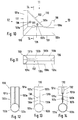
- the connecting element 130 or the connecting element parts 130a, 130b is also basic triangular, but here an embodiment is shown is a row system also at the terminal bicycle park can be used, i.e. in which only on one Side of a support leg 18 a connecting pipe section 14 is scheduled. If on both sides of the support leg 18 opposite sides each have a connecting pipe section 14 is attached, is also a second connecting element 130 in one around the left vertical edge symmetrical mirrored position to use.
- the connecting element 130 has the shape of a right triangle, the left vertical boundary from one of the associated support legs 18 laterally half of the clamping section 131 is formed, which is in a horizontal section over an arch extends to 180 °, the inner radius of the clamping section 131 equal to the outer radius of the support leg 18 is.
- the clamping section 131 in turn then settles again from clamp portion parts 131a and 131b, each Part of the connecting element parts 130a and 130b are.
- a clamping section 133 is formed, which of the associated connecting pipe sections 14 clamps around, and to a large extent completely, i.e. the clamping section 133 extends over - almost - 360 °.
- Each clamping section part 133a or 133b thus covers an arc of - almost - 180 °.
- Plastic is also another way of connecting of parts 130a, 130b conceivable.
- the connecting element trained push button-like locking elements be provided, which is a simple clipping on Parts 130a, 130b of the connecting element 130 from the front and rear of the connecting area of a support leg 18 with an associated connecting pipe section 14 enable.
- FIGS. 15 to 18 one is in its entirety 230 designated embodiment of a modified Connection element shown, which practically consists of two Share is composed, namely one in cross section corresponding to the outside diameter of the connecting pipe sections 14 arched base plate trained elongated Base element 233, which is in the connection area a connecting pipe section 14 with a support leg 18 can be placed on the connecting pipe section on which is made of an elongated metal profile, in the case shown, a flat iron, by Bending or bending into a series of metal profile sections divided component is attached and fastened, this attachment either by welding individual, sections lying on top of the base element or also by other common connecting means, such as riveting, screwing or the like. can be done.
- Fig. 15 it can be seen that the inclined and the front wheel of one to be inserted into a Parker Two-wheeler mandatory in the desired inclined position Boundary edge from the top of a portion 232 of the Metal profile is formed, one of which - in Fig. 15 right-hand end into one on base 233 attached angled intermediate section 235 passes over, while from his other obliquely up to the support leg led end one parallel to the support leg led down to the base element 233 and there again attached section 231 is attached.
- the profile material section forming the side stop projection 236 is integrally attached to the intermediate section 235 and is made up of sections, of which the Section 236a folded upwards from the intermediate section 235, the subsequent subsection 236b roughly into the horizontal position folded back and the next following Sub-sections 236c then again obliquely downwards Base element 233 folded over and fastened to the base element is.
- Below the profile material section 232 is in the middle in the base element 233 a - in the case shown as an elongated hole trained - mounting hole 238 provided, through which the shaft of a fastening screw can be screwed through.
- connection element 230 is for the Formation of the metal profile sections used metal profile a flat iron. It can be seen that instead of such a flat iron also other metal profiles, for example Round steel or tube profiles can be used can.
Landscapes
- Engineering & Computer Science (AREA)
- Mechanical Engineering (AREA)
- Fencing (AREA)
- Motorcycle And Bicycle Frame (AREA)
- Refuge Islands, Traffic Blockers, Or Guard Fence (AREA)
Description
- Fig. 1
- eine schematische Ansicht eines Ausschnitts einer Fahrradparker-Reihenanlage der hier in Frage stehenden Art;
- Fig. 2
- eine Ansicht der Anlage, gesehen in Richtung des Pfeils 2 in Fig. 1;
- Fig. 3
- eine in vergrößertem Maßstab gezeigte Teilansicht des Verbindungsbereichs eines Stützschenkels mit einem Verbindungs-Rohrabschnitt durch ein in der erfindungsgemäßen Weise ausgebildetes Knotenblech;
- Fig. 4
- eine Ansicht des in Fig. 3 vewendeten Knotenblechs;
- Fig. 5
- eine in der Blickrichtung der Fig. 3 entsprechende Ansicht des Verbindungsbereichs eines Stützschenkels mit einem Verbindungs-Rohrabschnitt unter Verwendung eines gegenüber dem in Fig. 4 gezeigten Knotenblech abgewandelten Knotenblechs;
- Fig. 6
- eine Ansicht, gesehen in Richtung des Pfeils 6 in Fig. 5;
- Fig. 7
- das abgewandelte Knotenblech in Blickrichtung auf eine seiner Flachseiten;
- Fig. 8
- eine Ansicht des Knotenblechs, gesehen in Richtung des Pfeils 8 in Fig. 7;
- Fig. 9
- eine Ansicht des Knotenblechs, gesehen in Richtung des Pfeils 9 in Fig. 7;
- Fig. 10
- eine Seitenansicht eines als Kunststoff-Spritzgußteil ausgebildeten Ausführungsbeispiels eines Verbindungselements zur Verbindung eines Stützschenkels mit einem Verbindungs-Rohrabschnitt;
- Fig. 11
- eine Ansicht des Verbindungselements gesehen in Richtung des Pfeils 11 in Fig. 10;
- Fig. 12
- eine Ansicht des Verbindungselements gesehen in Richtung des Pfeils 12 in Fig. 10;
- Fig. 13
- eine Ansicht gesehen in Richtung des Pfeils 13 in Fig. 10;
- Fig. 14
- eine Schnittansicht in der durch die Pfeile 14-14 in Fig. 10 angegebene Schnittebene;
- Fig. 15
- eine Seitenansicht eines weiteren Ausführungsbeispiels eines Verbindungselements;
- Fig. 16
- eine Ansicht des Verbindungselements, gesehen in Richtung des Pfeils 16 in Fig. 15;
- Fig. 17
- eine Ansicht des Verbindungselements, gesehen in Richtung des Pfeils 17 in Fig. 15; und
- Fig. 18
- eine Schnittansicht in der durch die Pfeile 18-18 in Fig. 15 veranschaulichten Schnittebene.
Claims (32)
- Fahrrad-Reihenanlage, aus einer Anzahl von Einzel- oder Doppel-Parkern, die jeweils einen in einer senkrechten Ebene angeordneten aus Rohrmaterial gebogenen Ständer aufweisen, der sich mit dem freien Ende wenigstens eines, vorzugsweise zweier Stützschenkel auf dem Boden abstützt oder in den Boden eingelassen ist, wobei einander zugeordnete Stützschenkel der Ständer benachbarter Parker durch horizontale Verbindungs-Rohrabschnitte verbunden sind, deren freie Enden jeweils am Stützschenkel eines der Parker befestigt sind,
dadurch gekennzeichnet,
daß im Befestigungsbereich der Verbindungs-Rohrabschnitte (14) mit den Stützschenkeln (18) ein im Bereich des jeweiligen Stützschenkels (18) über die Höhe der Rohrabschnitte (14) nach oben vorstehendes Verbindungselement (30; 30'; 130; 230) angeordnet ist, welches von seinem höchsten Punkt aus mit einer jeweils schräg verlaufenden Begrenzungskante (32; 132; 232) zu den anschließenden Verbindungs-Rohrabschnitten (14) herabgeführt ist. - Fahrradparker-Reihenanlage nach Anspruch 1, dadurch gekennzeichnet, daß das Verbindungselement an den Verbindungs-Rohrabschnitten (14) befestigt ist.
- Fahrradparker-Reihenanlage nach Anspruch 1 oder 2, dadurch gekennzeichnet, daß das Verbindungselement am Stützschenkel (18) befestigt ist.
- Fahrradparker-Reihenanlage nach einem der Ansprüche 1 bis 3, dadurch gekennzeichnet, daß die Verbindungselemente in ihrem zu den Verbindungs-Rohrabschnitten (14) herabgeführten Endbereichen mit jeweils einem über die Verbindungs-Rohrabschnitte (14) nach oben vortretenden, einen das seitliche Wegrutschen des Vorderrades eines eingestellten Fahrrades (24) verhindernden Seitenanschlag bildenden Ansatz (36; 136; 236) versehen sind.
- Fahrradparker-Reihenanlage nach einem der Ansprüche 1 bis 4, dadurch gekennzeichnet, daß die Verbindungselemente als Knotenbleche (30; 30') ausgebildet sind, welche die grundsätzliche Form eines gleichschenkligen Dreiecks haben, dessen Hypotenuse im wesentlichen in Höhe der unteren Begrenzung der Verbindungs-Rohrabschnitte (14) verläuft, während die Katheten die schräg verlaufenden Begrenzungskanten (32) bilden.
- Fahrradparker-Reihenanlage nach Anspruch 5, dadurch gekennzeichnet, daß die Seitenanschlag-Ansätze (36) im Bereich des Zusammentreffens der Katheten mit der Hypotenuse jeweils integral am Knotenblech (30; 30') angeschnitten sind.
- Fahrradparker-Reihenanlage nach Anspruch 5 oder 6, dadurch gekennzeichnet, daß das Knotenblech (30; 30') jeweils mittels Befestigungsschrauben am Stützschenkel (18) und/oder den Verbindungs-Rohrabschnitten (14) befestigt ist, und daß die Gewindeschäfte der Befestigungsschrauben durch Durchgangsöffnungen im Knotenblech (30; 30') hindurch in den jeweiligen Stützschenkel bzw. Verbindungs-Rohrabschnitt eingeschraubt sind.
- Fahrradparker-Reihenanlage nach einem der Ansprüche 5 bis 7, dadurch gekennzeichnet, daß im unteren hypotenusenseitigen Bereich des Knotenblechs (30') unterhalb jeder Kathete jeweils ein etwa rechtwinklig umgekanteter streifenförmiger Flanschabschnitt (42) angesetzt ist, welcher an der Unterseite der Verbindungs-Rohrabschnitte (14) anliegt.
- Fahrradparker-Reihenanlage nach Anspruch 8, dadurch gekennzeichnet, daß die Durchgangsöffnungen im Knotenblech (30; 30') als Langlöcher (38; 40) ausgebildet sind.
- Fahrradparker-Reihenanlage nach Anspruch 8 oder 9, bei welcher die Befestigung der Verbindungs-Rohrabschnitte (14) am zugeordneten Stützschenkel (18) des Ständers (16) durch am Stützschenkel (18) befestigte, passend in die offenen Enden der Verbindungs-Rohrabschnitte (14) eingreifende stopfenartige Verbindungsmuffen (28) erfolgt, dadurch gekennzeichnet, daß die Schäfte der Befestigungsschrauben durch Öffnungen (Langlöcher 38) im Knotenblech (30; 30') und dem jeweiligen Verbindungs-Rohrabschnitt (14) hindurch in eine Gewindebohrung in der jeweiligen Verbindungsmuffe (28) eingeschraubt sind.
- Fahrradparker-Reihenanlage nach einem der Ansprüche 5 bis 10, dadurch gekennzeichnet, daß die von den Katheten des dreieckigen Knotenblechs (30; 30') gebildeten schräg verlaufenden Begrenzungskanten (32) und/oder die dem Stützschenkel (18) zugewandten Begrenzungskanten (34) der Seitenanschlag-Ansätze (36) entgratet und/oder angefast bzw. abgerundet sind.
- Fahrradparker-Reihenanlage nach einem der Ansprüche 5 bis 10, dadurch gekennzeichnet, daß von den die Katheten des dreieckigen Knotenblechs (30; 30') bildenden schräg verlaufenden Begrenzungskanten einstückig angeschnittene Streifen des Blechmaterials umgekantet sind.
- Fahrradparker-Reihenanlage nach einem der Ansprüche 5 bis 12, dadurch gekennzeichnet, daß von der dem Stützschenkel (18) zugewandten Begrenzungskante (34) des Seitenanschlag-Ansatzes (36) jeweils ein einstückig angeschnittener Streifen des Blechmaterials des Knotenblechs (30; 30') umgekantet ist.
- Fahrradparker-Reihenanlage nach einem der Ansprüche 4 bis 13, bei welcher oberhalb der Verbindungs-Rohrabschnitte (14) an einem der Stützschenkel (18) des Ständers (16) jeweils ein das Vorderrad eines einzustellenden Fahrrades (24) auf der dem Ständer (16) gegenüberliegenden Seite umgreifender Seitenbügel (22) vorgesehen ist, dadurch gekennzeichnet, daß der lichte Abstand (A) der dem Stützschenkel (18) zugewandten Begrenzungskante (34) des Seitenanschlag-Ansatzes (36) vom zugeordneten Stützschenkel (18) wenigstens gleich dem lichten Abstand (a) zwischen dem Stützschenkel (18) und dem jeweiligen Seitenbügel (22) gewählt ist.
- Fahrradparker-Reihenanlage nach einem der Ansprüche 1 bis 4, dadurch gekennzeichnet, daß die Verbindungselemente (130) als Kunststoff-Spritzgußteile ausgebildet sind.
- Fahrradparker-Reihenanlage nach einem der Ansprüche 1 bis 4, dadurch gekennzeichnet, daß die Verbindungselemente (130) als Metall-Gußteile ausgebildet sind.
- Fahrradparker-Reihenanlage nach Anspruch 15 oder 16, dadurch gekennzeichnet, daß die Verbindungselemente (130) derart zweiteilig ausgebildet sind, daß sie den Verbindungsbereich des jeweiligen Stützschenkels (18) mit dem Endbereich des anschließenden Verbindungs-Rohrabschnitts (14) jeweils an der Vorder- bzw. Rückseite zumindest teilweise übergreifen, und daß der vorder- und rückseitige Teil (130a; 130b) des Verbindungselements (130) in der bestimmungsgemäßen Befestigungsstellung miteinander verbunden sind.
- Fahrradparker-Reihenanlage nach Anspruch 17, dadurch gekennzeichnet, daß die miteinander verbundenen vorder- und rückseitigen Teile (130a; 130b) des Verbindungselements (130) einen senkrechten, den Stützschenkel (18) über höchstens 180° seitlich umgreifenden und einen waagerechten, den zugeordneten Verbindungs-Rohrabschnitt (14) über mehr als 180° von der Oberseite aus umgreifenden Klemmabschnitt (131; 133) aufweisen, und daß die die schräge Begrenzungskante bildenden Abschnitte (132) sowie die den gegebenenfalls vorgesehenen Seitenanschlag-Ansatz (136) bildenden Abschnitte (136a; 136b) der Verbindungselement-Teile (130a; 130b) jeweils integral an den Klemmabschnitten (131; 133) angesetzt sind.
- Fahrradparker-Reihenanlage nach Anspruch 17 oder 18, dadurch gekennzeichnet, daß die Verbindungselement-Teile (130a; 130b) in der bestimmungsgemäßen Befestigungsstellung im Verbindungsbereich des Stützschenkels (18) und des zugeordneten Verbindungs-Rohrabschnitts (14) miteinander verschraubt sind.
- Fahrradparker-Reihenanlage nach Anspruch 17 oder 18, dadurch gekennzeichnet, daß die vorder- und rückseitigen Teile (130a; 130b) des Verbindungselements (130) in der bestimmungsgemäßen Befestigungsstellung durch formschlüssig ineinander eingreifende komplementäre Vorsprünge und Ausnehmungen miteinander verrastet sind.
- Fahrradparker-Reihananlage nach einem der Ansprüche 1 bis 4, dadurch gekennzeichnet, daß das Verbindungselement (230) ein jeweils im Befestigungsbereich eines Verbindungs-Rohrabschnitts (14) mit dem zugeordneten Stützschenkel (18) auf dem Verbindungs-Rohrabschnitt aufsetzbares und an ihm befestigbares langgestrecktes Basiselement (233) aufweist, auf dessen dem Verbindungs-Rohrabschnitt abgewandter Oberseite ein Abschnitt (232) eines langgestreckten metallischen Profilmaterials befestigt ist, welcher von seinem vom Stützschenkel entfernten Befestigungsbereich auf dem Basiselelement (233) aus schräg nach oben zum Stützschenkel (18) verläuft und so mit seiner dem Basiselement (233) abgewandte Seite die schräg verlaufende Begrenzungskante bildet.
- Fahrradparker-Reihenanlage nach Anspruch 21, dadurch gekennzeichnet, daß auf der stützschenkelabgewandten Seite des Befestigungsbereichs des schräg verlaufenden Profilmaterial-Abschnitts (232) auf dem Basiselement (233) ein ebenfalls von einem Abschnitt (236) eines metallischen Profilmaterials gebildeter, vom Basiselement vorstehender Seitenanschlag-Ansatz angeordnet ist.
- Fahrradparker-Reihenanlage nach Anspruch 22, dadurch gekennzeichnet, daß der vom Basiselement (233) vorstehende, den Seitenanschlag-Ansatz bildende Profilelement-Abschnitt (236) von einer Reihe von Teilabschnitten (236a, 236b, 236c) gebildet wird, von denen der erste Teilabschnitt (236a) vom Basiselement nach oben vortritt, während der sich anschließende Teilabschnitt (236b) in Richtung vom schräg verlaufenden Profilelement-Abschnitt (232) weg und der nachfolgende Teilabschnitt (236c) zum Basiselement (233) zurückgekantet oder -gebogen und am Basiselement befestigt ist.
- Fahrradparker-Reihenanlage nach einem der Ansprüche 21 bis 23, dadurch gekennzeichnet, daß am stützschenkelseitigen oberen Ende des die schräg verlaufende Begrenzungskante bildenden Profilmaterial-Abschnitts (232) ein parallel zum Stützschenkel (18) senkrecht nach unten bis zum Basiselement (233) geführter Abschnitt (231) des Profilmaterials angesetzt ist, dessen unteres Ende auf dem Basiselement (233) befestigt ist.
- Fahrradparker-Reihenanlage nach Anspruch 24, dadurch gekennzeichnet, daß in dem parallel zum Stützschenkel (18) zum Basiselement (233) geführten Profilmaterial-Abschnitt (231) eine Befestigungsbohrung (240) für den Schaft einer in eine Bohrung des Stützschenkels (18) befestigbaren Befestigungsschraube o.dgl. vorgesehen ist.
- Fahrradparker-Reihenanlage nach einem der Ansprüche 21 bis 25, dadurch gekennzeichnet, daß die Profilmaterial-Abschnitte (232; 236; 231) integrale Teile eines langgestreckten Metallprofils sind.
- Fahrradparker-Reihenanlage nach einem der Ansprüche 21 bis 26, dadurch gekennzeichnet, daß das Basiselement (233) von einer in ihrem Querschnitt kreisabschnittsförmig gewölbten metallischen Fußplatte gebildet wird, wobei der Radius der dem Verbindungs-Rohrabschnitt (14) zugewandten Seite der Fußplatte etwa gleich dem Radius der Außenfläche des zugeordneten Verbindungs-Rohrabschnitts (14) gewählt ist.
- Fahrradparker-Reihenanlage nach Anspruch 27, dadurch gekennzeichnet, daß die kreisabschnittsförmige Wölbung des Querschnitts der das Basiselement (233) bildenden Fußplatte sich über einen Winkel von maximal 180° erstreckt.
- Fahrradparker-Reihenanlage nach einem der Ansprüche 21 bis 28, dadurch gekennzeichnet, daß das Basiselement (233) im Bereich unterhalb des schräg verlaufenden Profilmaterial-Abschnitts (232) etwa mittig mit einer Befestigungsbohrung (238) für den Schaft einer Befestigungsschraube versehen ist.
- Fahrradparker-Reihenanlage nach Anspruch 29, dadurch gekennzeichnet, daß die Befestigungsbohrung (238) im Basiselement (233) in ihrer Lage so gewählt ist, daß sie mit einer Befestigungsbohrung im zugeordneten Verbindungs-Rohrabschnitt (14) fluchtet.
- Fahrradparker-Reihenanlage nach Anspruch 29 oder 30, dadurch gekennzeichnet, daß die Befestigungsbohrung (238) im Basiselement (233) als parallel zur Längsmittelachse des zugeordneten Verbindungs-Rohrabschnitts (14) verlaufendes Langgloch ausgebildet ist.
- Fahrradparker-Reihenanlage nach Anspruch 26, dadurch gekennzeichnet, daß das Metallprofil von einem Flach-, Rund- oder Rohrprofil gebildet wird.
Applications Claiming Priority (4)
| Application Number | Priority Date | Filing Date | Title |
|---|---|---|---|
| DE9409746U DE9409746U1 (de) | 1994-06-19 | 1994-06-19 | Fahrradparker-Reihenanlage |
| DE9409746U | 1994-06-19 | ||
| DE4430170A DE4430170C2 (de) | 1994-06-19 | 1994-08-25 | Fahrradparker-Reihenanlage |
| DE4430170 | 1994-08-25 |
Publications (2)
| Publication Number | Publication Date |
|---|---|
| EP0687619A1 EP0687619A1 (de) | 1995-12-20 |
| EP0687619B1 true EP0687619B1 (de) | 1998-03-25 |
Family
ID=25939513
Family Applications (1)
| Application Number | Title | Priority Date | Filing Date |
|---|---|---|---|
| EP95109074A Expired - Lifetime EP0687619B1 (de) | 1994-06-19 | 1995-06-13 | Fahrradparker-Reihenanlage |
Country Status (2)
| Country | Link |
|---|---|
| EP (1) | EP0687619B1 (de) |
| AT (1) | ATE164358T1 (de) |
Families Citing this family (2)
| Publication number | Priority date | Publication date | Assignee | Title |
|---|---|---|---|---|
| FR2756539B1 (fr) * | 1996-12-02 | 1998-12-24 | Fort Maurice Francois | Dispositif antivol support de bicyclettes |
| FR2758518B1 (fr) * | 1997-01-20 | 1999-04-09 | Cousin Jean Pierre Joseph | Dispositif antivol de stationnement pour cycles et cyclomoteurs |
Family Cites Families (5)
| Publication number | Priority date | Publication date | Assignee | Title |
|---|---|---|---|---|
| DE8715865U1 (de) | 1987-12-01 | 1988-01-21 | Groebe Feinstahlbau KG, 6525 Westhofen | Vorrichtung zum Einstellen von Zweirädern, wie Fahrrädern, Motorfahrrädern, Kleinkrafträdern o. dgl. |
| DE8801595U1 (de) * | 1988-02-09 | 1988-03-31 | FRIESON Handelsgesellschaft für Metall- und Kunststoffprodukte mbH & Co KG, 5909 Burbach | Fahrradständer |
| DE9006455U1 (de) * | 1990-06-08 | 1990-08-16 | Koch, Arnim, 3500 Kassel | Kombinations-Fahrradständer |
| DE9012662U1 (de) | 1990-09-05 | 1990-11-08 | Orion Bausysteme GmbH, 6083 Biebesheim | Rohr-Verbindung |
| DE9404105U1 (de) * | 1994-03-11 | 1994-05-05 | ORION Bausysteme GmbH, 64584 Biebesheim | Fahrradparker-Reihenanlage sowie Fundament- und Beschwerungspoller hierfür |
-
1995
- 1995-06-13 EP EP95109074A patent/EP0687619B1/de not_active Expired - Lifetime
- 1995-06-13 AT AT95109074T patent/ATE164358T1/de not_active IP Right Cessation
Also Published As
| Publication number | Publication date |
|---|---|
| ATE164358T1 (de) | 1998-04-15 |
| EP0687619A1 (de) | 1995-12-20 |
Similar Documents
| Publication | Publication Date | Title |
|---|---|---|
| EP0220395A1 (de) | Fahrradständer | |
| DE69932267T2 (de) | Zaun mit senkrechten Elementen | |
| DE2850763A1 (de) | Staender fuer fahrraeder, fahrraeder mit hilfsmotor und motorraeder | |
| DE4430170C2 (de) | Fahrradparker-Reihenanlage | |
| DE10065962A1 (de) | Metallprofil für Strassenmöbelkonstruktionen | |
| DE69817855T2 (de) | Schutzkonstruktion gegen wettereinflüsse | |
| DE4336363C1 (de) | Fahrradständermodul | |
| DE20005797U1 (de) | Depot für Fahrräder bestehend aus mindestens einer Fahrradaufhängung bzw. Fahrradhängeverschiebeeinheit | |
| EP0687619A1 (de) | Fahrradparker-Reihenanlage | |
| EP1464849B1 (de) | Höhenverstellbarer Standfuss | |
| EP3290309B1 (de) | Fahrrad-ausstellungsständer | |
| DE19502705C2 (de) | Traggestell für eine Badewanne oder Duschwanne | |
| DE9301629U1 (de) | Schwimmbadüberdachung aus mehreren auf Laufschienen verschiebbaren, bogenförmig gewölbten Teilschalen | |
| DE29712442U1 (de) | Mobile Absperrvorrichtung | |
| EP1518965A1 (de) | Leitschwellenanordnung | |
| DE29513037U1 (de) | Trägersystem | |
| DE69704178T2 (de) | Sichtzeichenständer | |
| DE4314677A1 (de) | Zweiradparkanlage | |
| DE9210060U1 (de) | Zweirad-Ständer | |
| EP0629544B1 (de) | Parkhalter für Zweiräder, insbesondere für Fahrräder | |
| DE3317885A1 (de) | Einrichtung zum abstellen von fahrraedern | |
| DE19629893A1 (de) | Befahrbare Abdeckung | |
| DE4327295A1 (de) | Zweirad-Parkbefestigung | |
| EP0455094A2 (de) | Adapter für Absperreinrichtungen | |
| DE29906558U1 (de) | Drahtzaun |
Legal Events
| Date | Code | Title | Description |
|---|---|---|---|
| PUAI | Public reference made under article 153(3) epc to a published international application that has entered the european phase |
Free format text: ORIGINAL CODE: 0009012 |
|
| AK | Designated contracting states |
Kind code of ref document: A1 Designated state(s): AT CH DK FR LI NL |
|
| 17P | Request for examination filed |
Effective date: 19960320 |
|
| GRAG | Despatch of communication of intention to grant |
Free format text: ORIGINAL CODE: EPIDOS AGRA |
|
| GRAG | Despatch of communication of intention to grant |
Free format text: ORIGINAL CODE: EPIDOS AGRA |
|
| GRAH | Despatch of communication of intention to grant a patent |
Free format text: ORIGINAL CODE: EPIDOS IGRA |
|
| 17Q | First examination report despatched |
Effective date: 19970904 |
|
| GRAH | Despatch of communication of intention to grant a patent |
Free format text: ORIGINAL CODE: EPIDOS IGRA |
|
| GRAA | (expected) grant |
Free format text: ORIGINAL CODE: 0009210 |
|
| AK | Designated contracting states |
Kind code of ref document: B1 Designated state(s): AT CH DK FR LI NL |
|
| PG25 | Lapsed in a contracting state [announced via postgrant information from national office to epo] |
Ref country code: NL Free format text: LAPSE BECAUSE OF FAILURE TO SUBMIT A TRANSLATION OF THE DESCRIPTION OR TO PAY THE FEE WITHIN THE PRESCRIBED TIME-LIMIT Effective date: 19980325 Ref country code: FR Free format text: LAPSE BECAUSE OF FAILURE TO SUBMIT A TRANSLATION OF THE DESCRIPTION OR TO PAY THE FEE WITHIN THE PRESCRIBED TIME-LIMIT Effective date: 19980325 |
|
| REF | Corresponds to: |
Ref document number: 164358 Country of ref document: AT Date of ref document: 19980415 Kind code of ref document: T |
|
| REG | Reference to a national code |
Ref country code: CH Ref legal event code: EP |
|
| PG25 | Lapsed in a contracting state [announced via postgrant information from national office to epo] |
Ref country code: AT Free format text: LAPSE BECAUSE OF NON-PAYMENT OF DUE FEES Effective date: 19980613 |
|
| PG25 | Lapsed in a contracting state [announced via postgrant information from national office to epo] |
Ref country code: DK Free format text: LAPSE BECAUSE OF FAILURE TO SUBMIT A TRANSLATION OF THE DESCRIPTION OR TO PAY THE FEE WITHIN THE PRESCRIBED TIME-LIMIT Effective date: 19980625 |
|
| EN | Fr: translation not filed | ||
| NLV1 | Nl: lapsed or annulled due to failure to fulfill the requirements of art. 29p and 29m of the patents act | ||
| PLBE | No opposition filed within time limit |
Free format text: ORIGINAL CODE: 0009261 |
|
| STAA | Information on the status of an ep patent application or granted ep patent |
Free format text: STATUS: NO OPPOSITION FILED WITHIN TIME LIMIT |
|
| 26N | No opposition filed | ||
| PG25 | Lapsed in a contracting state [announced via postgrant information from national office to epo] |
Ref country code: LI Free format text: LAPSE BECAUSE OF NON-PAYMENT OF DUE FEES Effective date: 19990630 Ref country code: CH Free format text: LAPSE BECAUSE OF NON-PAYMENT OF DUE FEES Effective date: 19990630 |
|
| REG | Reference to a national code |
Ref country code: CH Ref legal event code: PL |