EP0687633B1 - Tragetasche sowie Verfahren zu deren Herstellung und Anwendung - Google Patents
Tragetasche sowie Verfahren zu deren Herstellung und Anwendung Download PDFInfo
- Publication number
- EP0687633B1 EP0687633B1 EP95304168A EP95304168A EP0687633B1 EP 0687633 B1 EP0687633 B1 EP 0687633B1 EP 95304168 A EP95304168 A EP 95304168A EP 95304168 A EP95304168 A EP 95304168A EP 0687633 B1 EP0687633 B1 EP 0687633B1
- Authority
- EP
- European Patent Office
- Prior art keywords
- base portion
- side portions
- bag
- edges
- portions
- Prior art date
- Legal status (The legal status is an assumption and is not a legal conclusion. Google has not performed a legal analysis and makes no representation as to the accuracy of the status listed.)
- Expired - Lifetime
Links
- 238000000034 method Methods 0.000 title claims description 47
- 238000004519 manufacturing process Methods 0.000 title description 4
- 238000005520 cutting process Methods 0.000 claims description 10
- 239000004033 plastic Substances 0.000 claims description 3
- 229920003023 plastic Polymers 0.000 claims description 3
- 238000004806 packaging method and process Methods 0.000 description 24
- 230000000694 effects Effects 0.000 description 15
- 235000013305 food Nutrition 0.000 description 6
- 239000002985 plastic film Substances 0.000 description 4
- 229920006255 plastic film Polymers 0.000 description 4
- 235000012054 meals Nutrition 0.000 description 3
- 239000000123 paper Substances 0.000 description 3
- 241000251468 Actinopterygii Species 0.000 description 2
- 235000013194 Lyophyllum decastes Nutrition 0.000 description 2
- 240000005856 Lyophyllum decastes Species 0.000 description 2
- 241000270708 Testudinidae Species 0.000 description 2
- 235000012970 cakes Nutrition 0.000 description 2
- 235000013399 edible fruits Nutrition 0.000 description 2
- 235000015220 hamburgers Nutrition 0.000 description 2
- 239000000463 material Substances 0.000 description 2
- 235000013550 pizza Nutrition 0.000 description 2
- 229920003002 synthetic resin Polymers 0.000 description 2
- 239000000057 synthetic resin Substances 0.000 description 2
- 239000002023 wood Substances 0.000 description 2
- 230000015572 biosynthetic process Effects 0.000 description 1
- 239000007767 bonding agent Substances 0.000 description 1
- 230000007423 decrease Effects 0.000 description 1
- 230000001934 delay Effects 0.000 description 1
- 230000018109 developmental process Effects 0.000 description 1
- 239000004744 fabric Substances 0.000 description 1
- 230000012447 hatching Effects 0.000 description 1
- 230000002093 peripheral effect Effects 0.000 description 1
- 238000004080 punching Methods 0.000 description 1
- 238000007789 sealing Methods 0.000 description 1
- 238000009958 sewing Methods 0.000 description 1
- 235000014347 soups Nutrition 0.000 description 1
Images


Classifications
-
- B—PERFORMING OPERATIONS; TRANSPORTING
- B65—CONVEYING; PACKING; STORING; HANDLING THIN OR FILAMENTARY MATERIAL
- B65D—CONTAINERS FOR STORAGE OR TRANSPORT OF ARTICLES OR MATERIALS, e.g. BAGS, BARRELS, BOTTLES, BOXES, CANS, CARTONS, CRATES, DRUMS, JARS, TANKS, HOPPERS, FORWARDING CONTAINERS; ACCESSORIES, CLOSURES, OR FITTINGS THEREFOR; PACKAGING ELEMENTS; PACKAGES
- B65D31/00—Bags or like containers made of paper and having structural provision for thickness of contents
- B65D31/16—Bags or like containers made of paper and having structural provision for thickness of contents of special shape
-
- B—PERFORMING OPERATIONS; TRANSPORTING
- B65—CONVEYING; PACKING; STORING; HANDLING THIN OR FILAMENTARY MATERIAL
- B65D—CONTAINERS FOR STORAGE OR TRANSPORT OF ARTICLES OR MATERIALS, e.g. BAGS, BARRELS, BOTTLES, BOXES, CANS, CARTONS, CRATES, DRUMS, JARS, TANKS, HOPPERS, FORWARDING CONTAINERS; ACCESSORIES, CLOSURES, OR FITTINGS THEREFOR; PACKAGING ELEMENTS; PACKAGES
- B65D33/00—Details of, or accessories for, sacks or bags
- B65D33/06—Handles
- B65D33/08—Hand holes
-
- Y—GENERAL TAGGING OF NEW TECHNOLOGICAL DEVELOPMENTS; GENERAL TAGGING OF CROSS-SECTIONAL TECHNOLOGIES SPANNING OVER SEVERAL SECTIONS OF THE IPC; TECHNICAL SUBJECTS COVERED BY FORMER USPC CROSS-REFERENCE ART COLLECTIONS [XRACs] AND DIGESTS
- Y10—TECHNICAL SUBJECTS COVERED BY FORMER USPC
- Y10S—TECHNICAL SUBJECTS COVERED BY FORMER USPC CROSS-REFERENCE ART COLLECTIONS [XRACs] AND DIGESTS
- Y10S383/00—Flexible bags
- Y10S383/903—Stress relief
-
- Y—GENERAL TAGGING OF NEW TECHNOLOGICAL DEVELOPMENTS; GENERAL TAGGING OF CROSS-SECTIONAL TECHNOLOGIES SPANNING OVER SEVERAL SECTIONS OF THE IPC; TECHNICAL SUBJECTS COVERED BY FORMER USPC CROSS-REFERENCE ART COLLECTIONS [XRACs] AND DIGESTS
- Y10—TECHNICAL SUBJECTS COVERED BY FORMER USPC
- Y10S—TECHNICAL SUBJECTS COVERED BY FORMER USPC CROSS-REFERENCE ART COLLECTIONS [XRACs] AND DIGESTS
- Y10S493/00—Manufacturing container or tube from paper; or other manufacturing from a sheet or web
- Y10S493/916—Pliable container
- Y10S493/926—Pliable container having handle or suspension means
-
- Y—GENERAL TAGGING OF NEW TECHNOLOGICAL DEVELOPMENTS; GENERAL TAGGING OF CROSS-SECTIONAL TECHNOLOGIES SPANNING OVER SEVERAL SECTIONS OF THE IPC; TECHNICAL SUBJECTS COVERED BY FORMER USPC CROSS-REFERENCE ART COLLECTIONS [XRACs] AND DIGESTS
- Y10—TECHNICAL SUBJECTS COVERED BY FORMER USPC
- Y10S—TECHNICAL SUBJECTS COVERED BY FORMER USPC CROSS-REFERENCE ART COLLECTIONS [XRACs] AND DIGESTS
- Y10S493/00—Manufacturing container or tube from paper; or other manufacturing from a sheet or web
- Y10S493/916—Pliable container
- Y10S493/936—Square bottom
Definitions
- This invention is broadly concerned with a carry out bag for receiving therein take out foods, meals, products and articles, a producing method thereof and a using method thereof and intended particularly to be used to simply carry foods such as takeout lunch box, takeout dish, cake, expensive fruit, pizza and sliced raw fish.
- the general carry out bags are used by a store clerk to or by the customer to package food items for store removal.
- the store clerk or customer when using such bags now, first opens a new carry out bag using one hand holding the bag open, then places the item in the bag with the other hand. Subsequently, the received state of goods is coordinated. When the goods is a lunch box to be kept flat in the conventional carry out bag, the store clerk or shopper himself adjusts the state of the goods in the carry out bag.
- the square bottom type carry out bag assures stability of the goods therein when moving or carrying, but it may also require much time to be opened and to receive therein goods in the packaging as has been mentioned above.
- Figs. 7(A) and 7(B) are a carry out bag 80 to comfortably open its opening and to pack the goods, whereby the goods will be reliably carried.
- Fig 7(A) is a plane view of the proposed carry out bag 80 and
- Fig 7(B) is a sectional view taking along a line X-X in Fig 7(A) according to the Japanese Patent Application No. Hei 5-076981.
- the shown carry out bag 80 is made of plastic films and defined by a base portion 81 shaped into an almost hexagonal shape like a "shell of a tortoise" and a pair of side portions 90, 91 extended from opposing two sides 82, 83 of the base portion 81 facing each other.
- the side portions 90, 91 consist of two sections folded along fold lines 92, 93, one being the first side portions 90A, 91A and the other being the second side portions 90B, 91B.
- the respective second side portions 90B, 91B are each provided with a curved rectangular hole as a hand grip 94, 95.
- a using method example of such carry out bag 80 is to lay an article such as lunch box 96 across both fold lines 92, 93 from the upper side of the second side portions 90B, 91B as shown by a two-dotted line in Fig 7(A), to draw out the second side portions 90B, 91B laterally or to be separated one from the other in the directions of E and F, respectively, so that the second side portions 90B, 91B are completely pulled out from under the article 96, and to pull up straight the second side portions 90B, 91B corresponding to a base portion 81 as to meet both hand grips 94, 95 each other over the article 96.
- the carry out bag 80 taught in the Japanese Patent Application No. Hei 5-076981 assures smooth opening thereof and packaging for goods and further achieves a stable transportation of goods to some degree. But, if the width D of the respective second side portions 90B, 91B will be defined almost equal to or narrower than half the width H of the base portion 81 as depicted in Figs. 7(A), 7(B), when putting the article 96 on the respective second side portions 90B, 91B for packaging the article 96 sometimes hide the hand grip 94, 95 because of its dimensions or set position, which decreases efficiency of packaging.
- Figs. 7(A), 7(B), and hand grip 94 95 can not be punched out in the three-folded state in Figs. 7(A), 7(B), wherein the base portion 81, first side portion 90A, 91A and second side portion 90B, 91B are layered altogether, but requires other state to be punched out. Accordingly, a development of processes for producing the bag naturally involves some limitation for planning, so that a simplified producing method has been required in the market.
- GB-A-1338934 discloses a bag comprising a base portion having opposite side edges; first side portions connected to respective ones of the side edges of the base portion and extending inwardly overlying the base portion towards a middle area of the base portion, with end edges of the first side portions connected to respective ones of the end edges of the base portion; and second side portions connected to the inward edges of respective ones of the first side portions and extending outwardly overlying the first side portions to adjacent to or beyond the side edges of the base portion; the second side portions being provided with respective hand grips; and according to the present invention, such a bag is characterised in that the hand grips are grippable outwardly of the respective side edges of the base portion whereby the bag may be opened by raising and separating the hand grips.
- the end edges of the side portions are bonded to the base portion at an included obtuse angle to the side edges of the base portion.
- the base portion is formed into a polygon shape such as hexagon or octagon.
- the base portion may have cut out portions each having a semicircular shape at both side portions in the middle area.
- the respective second side portions may be provided with hand grips.
- the hole shape of the hand grip is preferable to be a curved rectangular hole, but it should not be limitedly considered since it is enough to be able to insert fingers thereinto.
- These grips can be provided as to be tied each other by having a triangle, trapezoid or convex shape, otherwise a set of eye and web.
- the carry out bag is recommended to be made of plastics.
- the bonding step between the side portions and the base portion is angularly carried out with reference to the opposing two sides facing each other.
- the producing method may further have the step of cutting out outer area at bonded portions before forming the three-folded portion and cutting out both side portions into a semicircular shape at the middle area of the base portion.
- the respective side portions can be provided with hand grips by cutting out.
- the cut out process for the hand grip may be carried out at the same time when cutting out both side portions at the middle area of the base portion.
- the using method according to the present invention is characterised to have the steps of putting an article across the both second side portions not to block up the hand grips therewith; and taking out the hand grips to pull out from under the article and to separate the second side portions one from the other, so that the article is received in the carry out bag.
- the fold line between the second and first side portions are pulled respectively to be separated one from the other to open the carry out bag to thereby receive therefrom the article.
- the article is put across the both second side portions from above the second side portions and thereafter the second side portions are pulled out respectively in opposed directions to be separated each other or from under the article, whereby the article can be completely and automatically packaged in.
- the present packaging procedure always assures that the article is always put flat on the base portion without any arrangement of the article, which means that there is no necessity to keep the opening open by one hand, while arranging the articles in the bag.
- the article can be flat on the base portion in the carry out bag, a reliability in transportation for the article can be improved. Supposing it is a lunch box, cake, hamburger, or fried chicken served in a simple case made of plastics, paper or wood, it can be kept flat in the bag.
- the first and second side portions are generally standing up with reference to the base portion via the opposing two sides. It will be further appropriate to expect some propaganda effect if a sales message is printed on the first side portion and/or the second side portion, particularly on the first side portion, because the side portion and the second side portion are stood straight from the side with reference to the base portion.
- the using state of the carry out bag presents a good appearance which further effects propaganda effect.
- the other sides of the first side portion and the base portion are angularly connected relatively to the opposing two sides of the base portion to form both side walls of the carry out bag with other sides of the base portion to thereby improve the entire appearance and stability in use to thereby develop its reliance to carry the article.
- the semicircle notches at both ends of the center line in the base portion improve an opening characteristic of the carry out bag and strengthen portions around the notches.
- the cut off process of the notches includes the same process for both ends of the center line of the respective heat-bonded portions, which assures fine finish of these ends.
- the notches further effect to lessen the bulk when plural carry out bags are stacked up, which will be advantageous for keeping and transporting them.
- To provide hand grips in the second side portions is to allow an easy transportation of the carry out bag receiving therein an article and an effective packaging.
- the carry out bag is provide to have the hand grips of the second side portions outside of the opposing two sides which are fold lines between the base portion and the first side portions, so that when putting the article on the second side portions, it does not naturally take place to block up the respective hand grips. Accordingly, the had grips can be picked up to separate both second side portions in the opposed directions respectively to thereby speedup total packaging efficiency.
- the parts of the second side portions each having the hand grip outside of the opposing two sides are disposed singly. Accordingly, the hand grips can be cut out in a three-folded state of the carry out bag, which causes to simplify the production steps to thereby achieve the above-mentioned objects.
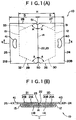
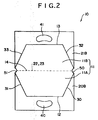
- FIG. 1(A), 1(B) and 2 A carry out bag 10 of the preferred embodiment according to the present invention is shown in Figs. 1(A), 1(B) and 2, Fig 1(A) being of a plane view thereof and Fig. 1(B) being of a sectional view taken along the X - X line in Fig. 1(A), and Fig. 2 being of a bottom view of the same.
- the carry out bag 10 is produced from plastic film and defined by a base portion 11 having a hexagonal shape like a "shell of a tortoise" and a pair of side portions 20, 21 extending from opposing two side 12, 13 of the base portion 11 facing to each other.
- the side portions 20, 21 have two sections folded along fold line 22, 23, one being the first side portions 20A, 21A and the other being the second side portions 20B, 21B.
- the base portion 11 is adapted to be able to be folded along a center line 14 so as to meet the sides 12 and 13 each other and two symmetrical trapezoid sections by the center line 14 will be denoted hereunder as a base portions 11A, 11B.
- the first side portions 20A, 21A should be understood as to each have the similar trapezoid shape as that of the base portions 11A, 11B.
- the first side portions 20A, 21A are respectively extended from the sides 12, 13 until a central area of the base portion 11, that is, each has half the width H of the base portion 11.
- the second side portion 20B, 21B almost has a rectangular shape which is successively extending from the central area (hold line 22, 23) of the base portion 11 so as to cross the side 12, 13. Accordingly, the width D of the second side portion 20B, 21B is larger than the half size of the width H.
- the rest sides of the base portion 11A, 11B are respectively heat-bonded (sealed) with rest sides of the first side portions, where will be referred to as a heat-bonded portion 30, 31, 32, 33.
- the heat-bonded portion 30-33 is angularly related at an angle of A to the center line 14 of the base portion 11 or the opposing two sides 12, 13 facing to each other.
- the angle A is generally in a range of 30 - 45 degrees.
- the second side portion 20B, 21B is provided with a crescent-shaped hole as a hand grip 40, 41.
- the peripheral portion of the second side portions 20B, 21B such as forward ends 24, 25 and side edges 26, 27, 28, 29 is not restrained with reference to any part of the carry out bag 10.
- notches 50, 51 at both ends of the center line 14 of the base portion 14 or at an adjoining corner of the respective base portions 11A, 11B.
- the notch 50, 51 is cut off to have a semicircular shape as can be seen from Fig. 1(A) when looking from the above.
- the notches 50, 51 should be understood as to be cut off from the first side portions 20A, 21A and the second side portions 20B, 21B, too.
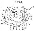
- FIG. 3 there is shown the carry out bag 10 in use according to the present invention, in which the opening is opened enough and an article 70 is depicted by two-dotted lines as has already packaged in the carry out bag 10.
- the opening 15 of the carry out bag 10 is defined by the fold lines 22, 23 shown in Fig. 1 and can be formed when the respective second side portions 20B, 21B are pulled out to separate one from the other.
- the carry out bag 10 in use forms its side walls, that is, a triangle portion 16 of which oblique sides are made by the heat-bonded portions 30 and 32 at the side edges of the base portion 11 and an opposite triangle portion 17 of which oblique sides are made by the heat-bonded portions 31 and 33.
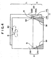
- a four-folded portion K is prepared with the base portion 11 folded along the center line 14 and the first side portions 20A and 21A as well as two-folded portion L made from the second side portions 20B and 21B.
- the base portions 11A, 11B and the first side portions 20A, 21A are not shaped into the already explained external form yet but still have a rectangular shape.
- edge portions of the base portions 11A, 11B and the first side portions 20A, 21A are rectangularly heat-bonded altogether to form the respective heat-bonded portions 30 - 33 as shown in Fig. 4.
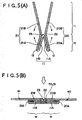
- the carry out bag shown in Fig. 4 will be further processed as shown in Figs. 5(A) and 5(B), that is, the side portion 20, 21 is folded along the fold line 22, 23 described with one-dotted line and the two-folded base portion 11 is spread in almost flat state to thereby form two sets three-folded parts M, each being piled up with the base portion 11A, 11B, first side portion 20A, 21A and the second side portion 20B, 21B in this order.
- both ends portions of the fold lines 22, 23 in the three-folded parts M are cut off in a semicircular shape to have the notches 50, 51.
- the second side portions 20B, 21B are further processed to have the hand grips 40, 41 outside of the three-folded parts M by being cut off in a crescent shape as can be seen from Fig. 5(B).
- both processes to make the notches 50, 51 and the hand grips 40, 41 can be done at the same time or individually.
- the processes for the notch 50, 51 and the hand grip 40, 41 are treated at the same time, the total producing steps for the carry out bag can be simplified.
- the notch 50, 51 may be made by cutting off, after the above-explained cut off process at the triangle portion shown by hatching in Fig. 4, into a semicircular shape around both ends of a one-dotted border line as shown in Fig. 4 between the four-folded portion K and the two-folded portion L.
- the hand grip 40, 41 may be formed in the two-folded portion L by cutting off the second side portions 20B, 21B altogether.
- the article such as lunch box 70 to be packaged should be put on the carry out bag 10 in a state to have the two sets three-folded parts M so that it is disposed on the second side portions 20B, 21B to across the fold lines 22, 23.
- the second side portions 20B, 21B are pulled out by means of the hand grips 40, 41 to be separated one from the other or in directions designated by the arrows E and F as to draw out the respective side portions 20B, 21B from under the article 70.
- the user is not required to dress the article 70 in the carry out bag 10 later because the article 70 can be smoothly or automatically shifted on the base portion 11 by carrying out the method explained with reference to Fig. 6. Accordingly, it will not be required to keep opening the opening of the carry out bag 10 by one hand and put the article therein and thereafter dress the article finally.
- the respective heat-bonded portions 30-33 are angularly provided from the sides 12, 13 and the triangle portion 16 of which oblique sides are made by the heat-bonded portions 30 and 32 and the opposite triangle portion 17 of which oblique sides are made by the heat-bonded portions 31 and 33 form side walls of the carry out bag to improve the entire appearance and stability in use to thereby develop its reliance to carry the article 70.
- the notches 50, 51 at both ends of the center line 14 of the base portion 11 improve an opening characteristic of the carry out bag and strengthen portions around the notches.
- the cut off process of the notches includes the same process for both ends of the center line 14 of the respective heat-bonded portions 30-33, which assures fine finish of these ends.
- the notches 50, 51 further effect to lessen the bulk when plural carry out bags 10 are stack up, which will be advantageous for keeping and transporting them.
- the hand grips 40, 41 are useful to carry the article 70 in the carry out bag and to pull out the respective second side portions 20B, 21B in the opposed direction E or F respectively as shown in Fig. 6 when packaging, whereby the packaging will be improved.
- This embodiment further achieves the following effects.
- the position of the hand grips 40, 41 is also preferable for users not to close the hand grips 40, 41 by the article 70 when carry out a relatively large article 70 on the second side portions 20B, 21B since they are disposed outside of the opposing two sides 12 and 13. Otherwise, the width D of the respective second side portions 20B, 21B may be made narrower to some degree than half the width H of the base portion 11, but supposing packaging into the carry out bag 10, the article 70 possibly blocks up the hand grips 40, 41 because of its scale or position when putting on the second side portions 20B, 21B. Accordingly, the users can pull out the hand grips 40, 41 to draw out the respective second side portions 20B, 21B as to move separately one from the other, which surely effects more smooth packaging.
- the cut off process for providing the hand grip 40, 41 can be carried out easily even in a state that the three-folded parts M have already organized as depicted in Fig. 5(B) since the hand grip 40, 41 will be made outside of the opposing two sides 12, 13. It can be therefore expected for the manufacturer to arrange and simplify processes freely as a whole.
- FIG. 1 show a state before using the carry out bag according to the present invention, but the wordings have been used based on a supposed using state.
- the respective first side portions 20A, 21A it is not always necessary for the respective first side portions 20A, 21A to have the width to almost reach at the central area of the base portion 11 from the opposing two sides 12, 13 in the foregoing embodiment, but it is enough to have some width extending toward the middle area of the base portion 11, that is, in the drawings shown by Figs. 1(A), 1(B), some space between the fold lines 22 and 23 is allowed.
- connection between the side edge of the base portion 11A, 11B and the side edge of the first side portion 20A, 21A is recommended to be done by a known heat-bonding (sealing) to form the heat-bonded portions 30, 31, 32, 33, but it may be carried out by another method such as a sewing, bonding agent or an ultrasonic waves.
- the heat-bonded portions 30, 31, 32, 33 are angularly related at an angle of A with reference to the center line 14 of the base portion 11 or the opposing two sides 12, 13, however they can be adjusted at a right angle to the opposing two sides 12, 13. However, it is recommended to be in a range of 30 - 45 degrees in view of its strength, function and external appearance.
- the shape of the base portion 11 is generally formed into a hexagonal shape cutting slantwise, but when cutting differently it can be of a octagonal one.
- the respective triangle portions, hatched area in Fig. 4, outside of the heat-bonded portions 30, 31, 32, 33 are cut off in general, but it can be remained, if it does not care to pay attention to its external appearance.
- the shape of hand grip 40, 41 in the above-mentioned embodiments is defined as to have the curved rectangular -shape but it may be of an oblong- or C-shape for convenience to receive thereinto fingers.
- the hand grip 40, 41 is not limited to be shaped into a hole shape but can be replaced with a projection extended from the forward end 24, 25 of the second side portion 20B, 21B.
- the set of projections are tied up to carry the carry out bag in which the article is received stably.
- the hand grip 40, 41 has been made by punching out the material plastic film in the embodiments, but it can be replaced with other grip such as a knot made by webs each extending from the forward end 24, 25 of the second side portion 20B, 21B or a set of hand grips each having eye to receive therein fingers.
- the respective side portions 20B, 21B are described to each have one hand grip 40, 41, but it is naturally allowed to have more than two hand grips respectively. Taking for an instance to have one more hand grip horizontally in relation to the normal hand grip 40, 41 shown in Figs. 3, the horizontally aligned hand grips will expand a choice of hand grips upon height of the article 70.
- the shape of the base portion 11 is defined as to be an almost hexagonal shape in the foregoing embodiments, but it may be of other shapes having opposing two sides 12, 13 and heat-bonded portions 30, 31, 32, 33 near the side edges.
- first side portion 20A, 21A is shaped into other ones.
- the second side portions 20B, 21B are defined to have a rectangular shape but since the forward end 24, 25 and side edge 26, 27, 28, 29 of the second side portion 20B, 21B, do not relate with other portions of the carry out bag 10, so that the shape of the forward end 24, 25 and the side edge 26, 27, 28, 29 can be defined occasionally and that of the second side portion 20B, 21B, is also allowed to have any shape.
- the side edge 26, 27, 28, 29 may be angularly formed to almost meet the heat-bonded portion 30, 31, 32, 33 to shape the second side portion 20B, 21B into the same shape as the first side portion 20A, 21A.
- the notch 50, 51 is defined as to be a semi-circular shape in the embodiments, but it can be of any shape.
- the notch 50, 51 can be provided occasionally, but it is preferable to be provided to improve easy opening and strength.
- the carry out bag 10 is made of plastic film in the embodiments, however its material should not be limitedly understood but may be of cloth, paper and the like.
- Thickness of the carry out bag is also optional.
- the described thickness of the carry out bag 10 in Figs. 1(B), 5(A), 5(B), 6 is exaggerated for explanation.
- the producing method and using method of the carry out bag in accordance with the present invention are not necessary to be limited into those of the already explained embodiment.
- the cut off process of the triangle portion, hatched area in Fig. 4, outside of the heat-bonded portion 30, 31, 32, 33 can be carried out after the formation of the notch 50, 51.
- the article 70 may be put into the carry out bag which is already opened by pulling out the second side portions 20B, 21B to be separated one from the other in a direction E and F respectively in Fig. 6.
- the carry out bag according to the present invention can be applied to package foods such as takeout lunch box, cake, hamburger, fried chicken, takeout dish, Japanese and western cake, expensive fruit, pizza, sliced raw fish, and various goods, products and articles.
- the carry out bag is preferable to package any box type object made of synthetic resin, paper or wood and covered with a simple packaging.
- the side portions of the carry out bag is originally folded to smoothly and easily open the carry out bag to receive thereinto the article, keep the article flat on the base portion, so that a stable transportation of the goods is reliably taken place and the bulk when plural carry out bags 10 are stacked up can be lessened, which will be advantageous for keeping and transporting them.
- the using state surely presents a good appearance which effects propaganda effect.
- the hand grips of the second side portions are provided outside of the opposing two sides as fold lines between the base portion and the first side portion, when the article put on the second side portions, the hand grips are not blocked up under the article, so that the packaging can be improved, and the cut out process of the hand grips can be finished in the three-folded state of the carry out bag to thereby simplify total steps for producing.
- the present invention performs a consecutive packaging only by putting the article on the piled up carry out bags, so that it is not necessary to pay attention to keep and move them when packaging.
Landscapes
- Engineering & Computer Science (AREA)
- Mechanical Engineering (AREA)
- Bag Frames (AREA)
- Making Paper Articles (AREA)
- Purses, Travelling Bags, Baskets, Or Suitcases (AREA)
Claims (12)
- Eine Tragetasche, bestehend aus einem Grundteil (11) mit einander gegenüberliegenden Seitenkanten (12, 13); ersten Seitenteilen (20A, 21A), die mit den jeweiligen entsprechenden Seitenkanten des Grundteils verbunden sind und sich nach innen erstrecken und dabei den Grundteil nach einem Mittelbereich (14) des Grundteils zu überlagern, mit Kanten (30-33) der ersten Seitenteile, die mit den entsprechenden Endkanten des Grundteils verbunden sind; und zweiten Seitenteilen (20B, 21B), die mit den Innenkanten (22, 23) der entsprechenden ersten Seitenteile verbunden sind und sich nach außen erstrecken und dabei die ersten Seitenteile bis an die, oder über die, Seitenkanten des Grundteils hinaus überlagern; wobei die zweiten Seitenteile mit entsprechenden Handgriffen (40, 41) versehen sind; dadurch gekennzeichnet, daß die Handgriffe von den entsprechenden Seitenkanten des Grundteils aus nach außen greifbar sind, wodurch die Taschen durch Heben und Trennen der Handgriffe voneinander geöffnet werden können.
- Eine Tragetasche gemäß Anspruch 1, bei der die Endkanten (30-33) der Seitenteile (20A, 21A) an den Grundteil (11) in einem eingeschlossenen stumpfen Winkel an die Seitenkanten (12, 13) des Grundteils (11) gebondet sind.
- Eine Tragetasche gemäß Anspruch 2, bei der der Grundteil (11) die Form eines Vielecks, wie z.B. eines Sechsecks oder eines Achteck hat.
- Eine Tragetasche gemäß einem beliebigen der vorstehenden Ansprüche, bei der die Handgriffe (40, 41) jeweils aus einer Öffnung bestehen, in die die Finger geschoben werden.
- Eine Tragetasche gemäß einem beliebigen der vorstehenden Ansprüche, bei der der Grundteil (11) ausgeschnittene Teile (50, 51) aufweist, die jeweils halbkreisförmige Form in der Mitte jeden Endes aufweisen.
- Eine Tragetasche gemäß einem beliebigen der vorstehenden Ansprüche, bei der die Seitenkanten der zweiten Seitenteile so ausgebildet sind, daß sie mit der Form des Grundteils übereinstimmend geformt sind.
- Eine Tragetasche gemaß einem beliebigen der vorstehenden Ansprüche, bei der die Tragetasche aus Kunststoff gemacht ist.
- Ein Verfahren zur Herstellung einer Tragetasche gemäß Anspruch 1, wobei das Verfahren die folgenden Schritte umfaßt: Falten eines Rohlings so, daß der Grundteil (11) entlang einer Mittelachse gefaltet wird, so daß sich seine gegenüberliegenden Seitenkanten (12, 13) einander nähern, und so daß die einander gegenüberliegenden Seitenkanten des Grundteils so gefaltet werden, daß sich die ersten Seitenteile (20A, 21A) entlang des Grundteils von den einander gegenüberliegenden Seitenkanten aus in Richtung zur Achse erstrecken, entlang der der Grundteil gefaltet ist; Bonden der Endkanten (30, 33) der ersten Seitenteile an die entsprechenden Endkanten des Grundteils; und Auseinanderklappen des Grundteils so, daß der Grundteil im wesentlichen planar wird, und so, daß die zweiten Seitenteile (20B, 21B) die entsprechenden ersten Seitenteile überlagern.
- Ein Verfahren zur Herstellung einer Tragetasche gemäß Anspruch 8, bei der die Endkanten (30, 33) des ersten Seitenteils an die entsprechenden der Endkanten des Grundteils (11) in einem eingeschlossenen stumpfen Winkel an die Seitenkanten des Grundteils gebondet sind.
- Ein Verfahren gemäß Anspruch 8 oder Anspruch 9, das ferner den Schritt des Ausschneidens eines Teils (50, 51) in Halbkreisform in der Mitte jeden Endes beinhaltet.
- Ein Verfahren gemäß Anspruch 10 worin der Handgriff (40, 41) zur gleichen Zeit ausgeschnitten wird wie die halbkreisförmigen Teile (50, 51) ausgeschnitten werden.
- Ein Verfahren zum Benutzen einer Tragetasche gemäß Anspruch 1, wobei das Verfahren die folgenden Schritte umfaßt: Setzen eines Artikels auf die zweiten Seitenteile (20B, 21B) einer ungeöffneten Tragetasche, so daß die Handgriffe (40) nicht verdeckt werden; Fassen der Handgriffe; und Herausziehen der zweiten Seitenteile unter dem Artikel und Bringen der Handgriffe über dem Artikel zueinander, so daß der Artikel auf dem Grundteil (11) sitzt und im Inneren der Tragetasche enthalten ist.
Applications Claiming Priority (2)
| Application Number | Priority Date | Filing Date | Title |
|---|---|---|---|
| JP135496/94 | 1994-06-17 | ||
| JP13549694 | 1994-06-17 |
Publications (2)
| Publication Number | Publication Date |
|---|---|
| EP0687633A1 EP0687633A1 (de) | 1995-12-20 |
| EP0687633B1 true EP0687633B1 (de) | 1998-09-30 |
Family
ID=15153106
Family Applications (1)
| Application Number | Title | Priority Date | Filing Date |
|---|---|---|---|
| EP95304168A Expired - Lifetime EP0687633B1 (de) | 1994-06-17 | 1995-06-15 | Tragetasche sowie Verfahren zu deren Herstellung und Anwendung |
Country Status (6)
| Country | Link |
|---|---|
| US (2) | US5741077A (de) |
| EP (1) | EP0687633B1 (de) |
| KR (1) | KR960000723A (de) |
| CN (1) | CN1037501C (de) |
| DE (1) | DE69505051T2 (de) |
| ES (1) | ES2124964T3 (de) |
Families Citing this family (23)
| Publication number | Priority date | Publication date | Assignee | Title |
|---|---|---|---|---|
| US6016950A (en) * | 1995-07-21 | 2000-01-25 | Pethick & Money Limited | Wrapper and method of its manufacture |
| JP2957535B2 (ja) * | 1998-01-26 | 1999-10-04 | 昌芳 松本 | 盤状物用手提げ袋の製造方法 |
| US7364360B2 (en) * | 2001-01-08 | 2008-04-29 | Urman Craig A | Package for horizontal transport |
| SE518918C2 (sv) | 2001-04-05 | 2002-12-03 | Tezzi Woldekidan | Påse för att bära lådformiga föremål |
| GB2376937A (en) * | 2001-06-14 | 2002-12-31 | Smithson Martin Dominic | Folded structure for forming a bag |
| US20040164575A1 (en) * | 2003-02-25 | 2004-08-26 | Generalplast S.R.L. | Bag for transportation of packaged goods, in particular food products ready for use |
| FR2862497A1 (fr) * | 2003-11-20 | 2005-05-27 | Jean Emile Salvador | Dispositif de protection amovible pour bagage |
| FR2863596A1 (fr) | 2003-12-12 | 2005-06-17 | Intelpack | Emballage pour le transport en position couchee et la presentation en position verticale d'une composition florale ou analogue |
| US6942100B2 (en) | 2004-02-13 | 2005-09-13 | Frank Su | Square bottomed plastic bag stack and method of making same |
| US20070223844A1 (en) * | 2006-03-21 | 2007-09-27 | Lisa Strama | Flexible container and method |
| US8746495B2 (en) * | 2008-12-01 | 2014-06-10 | S.C. Johnson Home Storage, Inc. | Flexible container |
| US8177431B2 (en) | 2008-12-01 | 2012-05-15 | S.C. Johnson Home Storage, Inc. | Flexible container |
| USD599550S1 (en) | 2008-12-01 | 2009-09-08 | S.C. Johnson Home Storage, Inc. | Flexible container |
| USD598194S1 (en) | 2008-12-01 | 2009-08-18 | S.C. Johnson Home Storage, Inc. | Flexible container |
| US20120037623A1 (en) * | 2010-08-16 | 2012-02-16 | Lucas Nancy Joy | Method and Apparatus for Containing Leftover Foods |
| US9352880B2 (en) | 2012-11-20 | 2016-05-31 | Pan Pacific Plastics Mfg., Inc. | Multi-orientation, reusable carrier assembly |
| USD719353S1 (en) | 2013-11-12 | 2014-12-16 | Pan Pacific Plastics Mfg., Inc. | Multipurpose reusable carrier bag |
| US9650178B2 (en) | 2014-01-16 | 2017-05-16 | The Fresh Group, Ltd. | Watermelon pouch |
| USD720237S1 (en) | 2014-01-22 | 2014-12-30 | The Fresh Group, Ltd | Watermelon pouch |
| WO2019122980A1 (en) * | 2017-12-20 | 2019-06-27 | Alpi Srl | Process for making container holding straps and product obtained therewith |
| US10793335B2 (en) | 2018-01-31 | 2020-10-06 | Inteplast Group Corporation | Tamper evident bag |
| CN108437561B (zh) * | 2018-03-28 | 2019-08-23 | 江苏南江智能装备股份有限公司 | 一种摆轮式纸质提手折叠装置及其折叠方法 |
| US10604305B2 (en) | 2018-03-30 | 2020-03-31 | Inteplast Group Corporation | Tamper evident bag |
Family Cites Families (14)
| Publication number | Priority date | Publication date | Assignee | Title |
|---|---|---|---|---|
| US2085766A (en) * | 1934-09-29 | 1937-07-06 | Potdevin Machine Co | Method of making bags and the like |
| US3549451A (en) * | 1968-03-06 | 1970-12-22 | Emanuel Kugler | Method of manufacturing satchel bottom bags |
| IE36093B1 (en) * | 1971-03-05 | 1976-08-18 | British Visqueen Ltd | Carrier-bags |
| GB1338934A (en) * | 1971-03-05 | 1973-11-28 | British Visqueen Ltd | Carrier-bags |
| GB1466379A (en) * | 1973-09-19 | 1977-03-09 | British Visqueen Ltd | Plastics carrier bags |
| FR2436719A1 (fr) * | 1978-09-19 | 1980-04-18 | Thibaut Toussaint | Sachet d'emballage etanche et son procede de fabrication |
| US4588392A (en) * | 1984-02-29 | 1986-05-13 | Mobil Oil Corporation | Method of forming a thermoplastic film sack having a stress relieved bottom gusset seal line |
| US4816104A (en) * | 1984-05-02 | 1989-03-28 | Mobil Oil Corporation | Methods and systems for preparing flat-bottom thermoplastic sack |
| US4895742A (en) * | 1988-07-22 | 1990-01-23 | Schaub Clemens B | Convertible receptacle |
| US4904093A (en) * | 1988-08-24 | 1990-02-27 | The Dow Chemical Comapny | Gussetted plastic bags having relief seals and method of making same |
| DE8815895U1 (de) * | 1988-12-22 | 1989-03-16 | Stiegler GmbH Maschinenfabrik, 7062 Rudersberg | Maschine zum Herstellen von Tragetaschen mit Grifflöchern und diese umgebenden angeschweißten Verstärkungszetteln aus thermoplastischem Kunststoff |
| WO1992009493A1 (en) * | 1990-11-28 | 1992-06-11 | Crafoord, Anne | Bag for carrying box-shaped objects |
| JP2890917B2 (ja) | 1991-09-17 | 1999-05-17 | 日産自動車株式会社 | フランジ付歯車の製造方法 |
| DE4225998C2 (de) * | 1992-08-06 | 1998-04-16 | Mildenberger & Willing Verpack | Verfahren zur Herstellung von Verpackungsbeuteln mit Griffstück |
-
1995
- 1995-06-15 ES ES95304168T patent/ES2124964T3/es not_active Expired - Lifetime
- 1995-06-15 EP EP95304168A patent/EP0687633B1/de not_active Expired - Lifetime
- 1995-06-15 DE DE69505051T patent/DE69505051T2/de not_active Expired - Fee Related
- 1995-06-16 CN CN95108449A patent/CN1037501C/zh not_active Expired - Fee Related
- 1995-06-16 US US08/491,283 patent/US5741077A/en not_active Expired - Fee Related
- 1995-06-17 KR KR1019950016202A patent/KR960000723A/ko not_active Ceased
-
1997
- 1997-12-12 US US08/989,484 patent/US5947884A/en not_active Expired - Fee Related
Also Published As
| Publication number | Publication date |
|---|---|
| US5947884A (en) | 1999-09-07 |
| CN1121030A (zh) | 1996-04-24 |
| DE69505051D1 (de) | 1998-11-05 |
| ES2124964T3 (es) | 1999-02-16 |
| CN1037501C (zh) | 1998-02-25 |
| US5741077A (en) | 1998-04-21 |
| EP0687633A1 (de) | 1995-12-20 |
| KR960000723A (ko) | 1996-01-25 |
| DE69505051T2 (de) | 1999-04-08 |
Similar Documents
| Publication | Publication Date | Title |
|---|---|---|
| US5741077A (en) | Carry out bag, method of producing the same and method of using the same | |
| US4241863A (en) | Container with multiple compartments | |
| CA1334187C (en) | Compact package for food product or the like | |
| EP1098823B1 (de) | Verbesserung an oder bezüglich lebensmittelpackungen | |
| EP0844971B1 (de) | Verbesserungen an behältern für verkaufsartikel | |
| CN1124965C (zh) | 铰接的容器 | |
| US6588652B2 (en) | Food tray with condiment compartment | |
| US20260021932A1 (en) | Container with integral condiment pocket | |
| US6312157B1 (en) | Packaging bags and method of producing same | |
| KR101344558B1 (ko) | 양측단에 연결부를 갖고 횡방향으로 다수 연결된 지퍼백 | |
| JP4139507B2 (ja) | 包装用容器 | |
| JP2672765B2 (ja) | 包装用袋およびその製造方法およびその使用方法 | |
| US5955133A (en) | Methods for wrapping sandwich type products | |
| JPH0235212Y2 (de) | ||
| JPH0858808A (ja) | 包装用袋およびその使用方法およびその製造方法 | |
| JP2754468B2 (ja) | 容 器 | |
| JP2003502224A (ja) | 積み重ね可能な包装システム | |
| KR200492619Y1 (ko) | 형상변경이 자유로운 골판지 및 이를 이용한 파우치 | |
| JPS6311086Y2 (de) | ||
| KR102114725B1 (ko) | 다중 시트를 구비하는 연결형 포켓 시스템 | |
| JP2004284595A (ja) | 果実等陳列兼用収容パック、およびそれを用いた桜桃果実の梱包方法 | |
| JPH0215792Y2 (de) | ||
| JP2507719Y2 (ja) | 盤状物用手提げ袋 | |
| JP2005138845A (ja) | 包装袋 | |
| JPS6311088Y2 (de) |
Legal Events
| Date | Code | Title | Description |
|---|---|---|---|
| PUAI | Public reference made under article 153(3) epc to a published international application that has entered the european phase |
Free format text: ORIGINAL CODE: 0009012 |
|
| AK | Designated contracting states |
Kind code of ref document: A1 Designated state(s): BE DE ES FR GB IT NL SE |
|
| 17P | Request for examination filed |
Effective date: 19960607 |
|
| 17Q | First examination report despatched |
Effective date: 19970530 |
|
| GRAG | Despatch of communication of intention to grant |
Free format text: ORIGINAL CODE: EPIDOS AGRA |
|
| GRAG | Despatch of communication of intention to grant |
Free format text: ORIGINAL CODE: EPIDOS AGRA |
|
| GRAH | Despatch of communication of intention to grant a patent |
Free format text: ORIGINAL CODE: EPIDOS IGRA |
|
| GRAH | Despatch of communication of intention to grant a patent |
Free format text: ORIGINAL CODE: EPIDOS IGRA |
|
| GRAA | (expected) grant |
Free format text: ORIGINAL CODE: 0009210 |
|
| AK | Designated contracting states |
Kind code of ref document: B1 Designated state(s): BE DE ES FR GB IT NL SE |
|
| PG25 | Lapsed in a contracting state [announced via postgrant information from national office to epo] |
Ref country code: NL Free format text: LAPSE BECAUSE OF FAILURE TO SUBMIT A TRANSLATION OF THE DESCRIPTION OR TO PAY THE FEE WITHIN THE PRESCRIBED TIME-LIMIT Effective date: 19980930 Ref country code: BE Free format text: LAPSE BECAUSE OF FAILURE TO SUBMIT A TRANSLATION OF THE DESCRIPTION OR TO PAY THE FEE WITHIN THE PRESCRIBED TIME-LIMIT Effective date: 19980930 |
|
| REF | Corresponds to: |
Ref document number: 69505051 Country of ref document: DE Date of ref document: 19981105 |
|
| ET | Fr: translation filed | ||
| PG25 | Lapsed in a contracting state [announced via postgrant information from national office to epo] |
Ref country code: SE Free format text: LAPSE BECAUSE OF FAILURE TO SUBMIT A TRANSLATION OF THE DESCRIPTION OR TO PAY THE FEE WITHIN THE PRESCRIBED TIME-LIMIT Effective date: 19981231 |
|
| REG | Reference to a national code |
Ref country code: ES Ref legal event code: FG2A Ref document number: 2124964 Country of ref document: ES Kind code of ref document: T3 |
|
| NLV1 | Nl: lapsed or annulled due to failure to fulfill the requirements of art. 29p and 29m of the patents act | ||
| PLBE | No opposition filed within time limit |
Free format text: ORIGINAL CODE: 0009261 |
|
| STAA | Information on the status of an ep patent application or granted ep patent |
Free format text: STATUS: NO OPPOSITION FILED WITHIN TIME LIMIT |
|
| 26N | No opposition filed | ||
| REG | Reference to a national code |
Ref country code: GB Ref legal event code: IF02 |
|
| PGFP | Annual fee paid to national office [announced via postgrant information from national office to epo] |
Ref country code: FR Payment date: 20020610 Year of fee payment: 8 |
|
| PGFP | Annual fee paid to national office [announced via postgrant information from national office to epo] |
Ref country code: GB Payment date: 20020612 Year of fee payment: 8 |
|
| PGFP | Annual fee paid to national office [announced via postgrant information from national office to epo] |
Ref country code: ES Payment date: 20020618 Year of fee payment: 8 |
|
| PGFP | Annual fee paid to national office [announced via postgrant information from national office to epo] |
Ref country code: DE Payment date: 20020619 Year of fee payment: 8 |
|
| PG25 | Lapsed in a contracting state [announced via postgrant information from national office to epo] |
Ref country code: GB Free format text: LAPSE BECAUSE OF NON-PAYMENT OF DUE FEES Effective date: 20030615 |
|
| PG25 | Lapsed in a contracting state [announced via postgrant information from national office to epo] |
Ref country code: ES Free format text: LAPSE BECAUSE OF NON-PAYMENT OF DUE FEES Effective date: 20030616 |
|
| PG25 | Lapsed in a contracting state [announced via postgrant information from national office to epo] |
Ref country code: DE Free format text: LAPSE BECAUSE OF NON-PAYMENT OF DUE FEES Effective date: 20040101 |
|
| GBPC | Gb: european patent ceased through non-payment of renewal fee |
Effective date: 20030615 |
|
| PG25 | Lapsed in a contracting state [announced via postgrant information from national office to epo] |
Ref country code: FR Free format text: LAPSE BECAUSE OF NON-PAYMENT OF DUE FEES Effective date: 20040227 |
|
| REG | Reference to a national code |
Ref country code: FR Ref legal event code: ST |
|
| REG | Reference to a national code |
Ref country code: ES Ref legal event code: FD2A Effective date: 20030616 |
|
| PG25 | Lapsed in a contracting state [announced via postgrant information from national office to epo] |
Ref country code: IT Free format text: LAPSE BECAUSE OF NON-PAYMENT OF DUE FEES Effective date: 20050615 |