EP0687642B1 - Vorrichtung zum Speichern sowie zum Auf- und Abwickeln eines flexiblen, biegsamen Stabes - Google Patents
Vorrichtung zum Speichern sowie zum Auf- und Abwickeln eines flexiblen, biegsamen Stabes Download PDFInfo
- Publication number
- EP0687642B1 EP0687642B1 EP94106111A EP94106111A EP0687642B1 EP 0687642 B1 EP0687642 B1 EP 0687642B1 EP 94106111 A EP94106111 A EP 94106111A EP 94106111 A EP94106111 A EP 94106111A EP 0687642 B1 EP0687642 B1 EP 0687642B1
- Authority
- EP
- European Patent Office
- Prior art keywords
- reel
- stand
- rod
- tube
- spokes
- Prior art date
- Legal status (The legal status is an assumption and is not a legal conclusion. Google has not performed a legal analysis and makes no representation as to the accuracy of the status listed.)
- Expired - Lifetime
Links
- 238000004804 winding Methods 0.000 title claims abstract description 9
- 230000007935 neutral effect Effects 0.000 claims description 3
- 238000010276 construction Methods 0.000 description 2
- 238000000034 method Methods 0.000 description 2
- 208000027418 Wounds and injury Diseases 0.000 description 1
- 238000005452 bending Methods 0.000 description 1
- 230000006835 compression Effects 0.000 description 1
- 238000007906 compression Methods 0.000 description 1
- 230000006378 damage Effects 0.000 description 1
- 238000010586 diagram Methods 0.000 description 1
- 230000000694 effects Effects 0.000 description 1
- 208000014674 injury Diseases 0.000 description 1
- 230000003014 reinforcing effect Effects 0.000 description 1
- 230000006641 stabilisation Effects 0.000 description 1
- 238000011105 stabilization Methods 0.000 description 1
Images




Classifications
-
- B—PERFORMING OPERATIONS; TRANSPORTING
- B65—CONVEYING; PACKING; STORING; HANDLING THIN OR FILAMENTARY MATERIAL
- B65H—HANDLING THIN OR FILAMENTARY MATERIAL, e.g. SHEETS, WEBS, CABLES
- B65H75/00—Storing webs, tapes, or filamentary material, e.g. on reels
- B65H75/02—Cores, formers, supports, or holders for coiled, wound, or folded material, e.g. reels, spindles, bobbins, cop tubes, cans, mandrels or chucks
- B65H75/34—Cores, formers, supports, or holders for coiled, wound, or folded material, e.g. reels, spindles, bobbins, cop tubes, cans, mandrels or chucks specially adapted or mounted for storing and repeatedly paying-out and re-storing lengths of material provided for particular purposes, e.g. anchored hoses, power cables
- B65H75/36—Cores, formers, supports, or holders for coiled, wound, or folded material, e.g. reels, spindles, bobbins, cop tubes, cans, mandrels or chucks specially adapted or mounted for storing and repeatedly paying-out and re-storing lengths of material provided for particular purposes, e.g. anchored hoses, power cables without essentially involving the use of a core or former internal to a stored package of material, e.g. with stored material housed within casing or container, or intermittently engaging a plurality of supports as in sinuous or serpentine fashion
- B65H75/362—Cores, formers, supports, or holders for coiled, wound, or folded material, e.g. reels, spindles, bobbins, cop tubes, cans, mandrels or chucks specially adapted or mounted for storing and repeatedly paying-out and re-storing lengths of material provided for particular purposes, e.g. anchored hoses, power cables without essentially involving the use of a core or former internal to a stored package of material, e.g. with stored material housed within casing or container, or intermittently engaging a plurality of supports as in sinuous or serpentine fashion with stored material housed within a casing or container
- B65H75/364—Cores, formers, supports, or holders for coiled, wound, or folded material, e.g. reels, spindles, bobbins, cop tubes, cans, mandrels or chucks specially adapted or mounted for storing and repeatedly paying-out and re-storing lengths of material provided for particular purposes, e.g. anchored hoses, power cables without essentially involving the use of a core or former internal to a stored package of material, e.g. with stored material housed within casing or container, or intermittently engaging a plurality of supports as in sinuous or serpentine fashion with stored material housed within a casing or container the stored material being coiled
-
- B—PERFORMING OPERATIONS; TRANSPORTING
- B65—CONVEYING; PACKING; STORING; HANDLING THIN OR FILAMENTARY MATERIAL
- B65H—HANDLING THIN OR FILAMENTARY MATERIAL, e.g. SHEETS, WEBS, CABLES
- B65H75/00—Storing webs, tapes, or filamentary material, e.g. on reels
- B65H75/02—Cores, formers, supports, or holders for coiled, wound, or folded material, e.g. reels, spindles, bobbins, cop tubes, cans, mandrels or chucks
- B65H75/34—Cores, formers, supports, or holders for coiled, wound, or folded material, e.g. reels, spindles, bobbins, cop tubes, cans, mandrels or chucks specially adapted or mounted for storing and repeatedly paying-out and re-storing lengths of material provided for particular purposes, e.g. anchored hoses, power cables
- B65H75/38—Cores, formers, supports, or holders for coiled, wound, or folded material, e.g. reels, spindles, bobbins, cop tubes, cans, mandrels or chucks specially adapted or mounted for storing and repeatedly paying-out and re-storing lengths of material provided for particular purposes, e.g. anchored hoses, power cables involving the use of a core or former internal to, and supporting, a stored package of material
- B65H75/40—Cores, formers, supports, or holders for coiled, wound, or folded material, e.g. reels, spindles, bobbins, cop tubes, cans, mandrels or chucks specially adapted or mounted for storing and repeatedly paying-out and re-storing lengths of material provided for particular purposes, e.g. anchored hoses, power cables involving the use of a core or former internal to, and supporting, a stored package of material mobile or transportable
- B65H75/403—Carriage with wheels
-
- B—PERFORMING OPERATIONS; TRANSPORTING
- B65—CONVEYING; PACKING; STORING; HANDLING THIN OR FILAMENTARY MATERIAL
- B65H—HANDLING THIN OR FILAMENTARY MATERIAL, e.g. SHEETS, WEBS, CABLES
- B65H75/00—Storing webs, tapes, or filamentary material, e.g. on reels
- B65H75/02—Cores, formers, supports, or holders for coiled, wound, or folded material, e.g. reels, spindles, bobbins, cop tubes, cans, mandrels or chucks
- B65H75/34—Cores, formers, supports, or holders for coiled, wound, or folded material, e.g. reels, spindles, bobbins, cop tubes, cans, mandrels or chucks specially adapted or mounted for storing and repeatedly paying-out and re-storing lengths of material provided for particular purposes, e.g. anchored hoses, power cables
- B65H75/38—Cores, formers, supports, or holders for coiled, wound, or folded material, e.g. reels, spindles, bobbins, cop tubes, cans, mandrels or chucks specially adapted or mounted for storing and repeatedly paying-out and re-storing lengths of material provided for particular purposes, e.g. anchored hoses, power cables involving the use of a core or former internal to, and supporting, a stored package of material
- B65H75/44—Constructional details
- B65H75/4402—Guiding arrangements to control paying-out and re-storing of the material
-
- B—PERFORMING OPERATIONS; TRANSPORTING
- B65—CONVEYING; PACKING; STORING; HANDLING THIN OR FILAMENTARY MATERIAL
- B65H—HANDLING THIN OR FILAMENTARY MATERIAL, e.g. SHEETS, WEBS, CABLES
- B65H75/00—Storing webs, tapes, or filamentary material, e.g. on reels
- B65H75/02—Cores, formers, supports, or holders for coiled, wound, or folded material, e.g. reels, spindles, bobbins, cop tubes, cans, mandrels or chucks
- B65H75/34—Cores, formers, supports, or holders for coiled, wound, or folded material, e.g. reels, spindles, bobbins, cop tubes, cans, mandrels or chucks specially adapted or mounted for storing and repeatedly paying-out and re-storing lengths of material provided for particular purposes, e.g. anchored hoses, power cables
- B65H75/38—Cores, formers, supports, or holders for coiled, wound, or folded material, e.g. reels, spindles, bobbins, cop tubes, cans, mandrels or chucks specially adapted or mounted for storing and repeatedly paying-out and re-storing lengths of material provided for particular purposes, e.g. anchored hoses, power cables involving the use of a core or former internal to, and supporting, a stored package of material
- B65H75/44—Constructional details
- B65H75/4481—Arrangements or adaptations for driving the reel or the material
- B65H75/4486—Electric motors
-
- B—PERFORMING OPERATIONS; TRANSPORTING
- B65—CONVEYING; PACKING; STORING; HANDLING THIN OR FILAMENTARY MATERIAL
- B65H—HANDLING THIN OR FILAMENTARY MATERIAL, e.g. SHEETS, WEBS, CABLES
- B65H75/00—Storing webs, tapes, or filamentary material, e.g. on reels
- B65H75/02—Cores, formers, supports, or holders for coiled, wound, or folded material, e.g. reels, spindles, bobbins, cop tubes, cans, mandrels or chucks
- B65H75/34—Cores, formers, supports, or holders for coiled, wound, or folded material, e.g. reels, spindles, bobbins, cop tubes, cans, mandrels or chucks specially adapted or mounted for storing and repeatedly paying-out and re-storing lengths of material provided for particular purposes, e.g. anchored hoses, power cables
- B65H75/38—Cores, formers, supports, or holders for coiled, wound, or folded material, e.g. reels, spindles, bobbins, cop tubes, cans, mandrels or chucks specially adapted or mounted for storing and repeatedly paying-out and re-storing lengths of material provided for particular purposes, e.g. anchored hoses, power cables involving the use of a core or former internal to, and supporting, a stored package of material
- B65H75/44—Constructional details
- B65H75/4481—Arrangements or adaptations for driving the reel or the material
- B65H75/4492—Manual drives
-
- H—ELECTRICITY
- H02—GENERATION; CONVERSION OR DISTRIBUTION OF ELECTRIC POWER
- H02G—INSTALLATION OF ELECTRIC CABLES OR LINES, OR OF COMBINED OPTICAL AND ELECTRIC CABLES OR LINES
- H02G1/00—Methods or apparatus specially adapted for installing, maintaining, repairing or dismantling electric cables or lines
- H02G1/06—Methods or apparatus specially adapted for installing, maintaining, repairing or dismantling electric cables or lines for laying cables, e.g. laying apparatus on vehicle
- H02G1/08—Methods or apparatus specially adapted for installing, maintaining, repairing or dismantling electric cables or lines for laying cables, e.g. laying apparatus on vehicle through tubing or conduit, e.g. rod or draw wire for pushing or pulling
-
- B—PERFORMING OPERATIONS; TRANSPORTING
- B65—CONVEYING; PACKING; STORING; HANDLING THIN OR FILAMENTARY MATERIAL
- B65H—HANDLING THIN OR FILAMENTARY MATERIAL, e.g. SHEETS, WEBS, CABLES
- B65H2701/00—Handled material; Storage means
- B65H2701/30—Handled filamentary material
- B65H2701/37—Tapes
- B65H2701/376—Electrician's fish tapes
Definitions
- the invention relates to a device for storage as well as for winding and unwinding a flexible, bendable Rod for pulling cables into cable protection tubes, wherein a reel wheel by means of an axis of rotation on a Frame is rotatably mounted and the reel wheel from radial reel spokes starting from the axis of rotation has which so on the outer circumference of the reel wheel are bent so that the rod on the inside in Turns.
- a device of the type specified above is from the EP 0403671 A1 known.
- the flexible, pliable rod in turns on the inside of the outer circumference of the reel wheel because of the flexible Rod inherent in a tension that strives to the rod to keep it as straight or straight as possible.
- the reel wheel has spokes that are approximately semicircular on the outer circumference are bent and the ends with a all-round connecting and reinforcing ring connected are.
- To pull the rod out of the reel wheel can one side of the reel wheel within the circumferential ring be completely open. With this device the artisan must remove the flexible rod by hand from the Pull out the reel wheel, the reel wheel moving accordingly rotates about an axis of rotation.
- the stick must then be done by hand inserted into a cable protection tube and through the cable protection tube pushed to the other end.
- the cable to be pulled into the cable protection tube at the end attached to the rod and retracting the flexible Rod pulled into the cable protection tube.
- the flexible rod can be pushed back into the reel wheel, whereby he again because of said internal tension applied in turns.
- a device according to the preamble of claim 1 is known DE-U-1 911 053 known.
- the invention has for its object a device to create that allows easy operation and at which it is possible to apply large forces to the flexible rod transmitted and thus cable over a very long length of a Retract the cable protection tube.
- the object is achieved in that the reel wheel is provided with a drive that on the outside A circumferential gap is provided around the circumference of the reel wheel is in which a fixed ring is arranged is that the fixed ring is an outlet for the Has rod, and that between the opposite Reel spokes at a distance from the outer circumference of the Haspelrades inner abutments for the rod attached are.
- Figures 1 to 4 show an embodiment of a device according to the invention.
- the frame has a one-piece frame tube 3 and two more on both sides of the reel wheel Frame tubes 4 on.
- the frame tube 3 is formed in one piece and is about on both sides of the reel wheel 2 Z-shaped curved. It has the reel wheel on both sides horizontal lower tube parts 5, directed obliquely upwards Pipe parts 6, intermediate pipe parts 7 and more at an angle upward pipe parts 8, which at the upper end in pass over an upper pipe bend 9.
- the other two Pipe parts on both sides of the reel wheel 2 each have a lower horizontal pipe part 10, an obliquely upwards directed pipe part 11 and a bent obliquely upward pipe part 12, the latter attached with an end bend 13 to the tube part 8 of the tube 3 is, as Figure 1 illustrates.
- the pipe part 7 and the upper run End of the tube part 11 essentially parallel to one another, and with such a distance that on them both Side of the reel wheel 2 axle bearing plates 14 and 15 attached are in which the bearings for the axis of rotation 16th of the reel wheel.
- the two-sided pipe parts 5 and 10 are firmly connected.
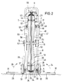
- the reel wheel 2 has a number of reel wheel spokes 17, 18 on which at its inner end on the axis of rotation 16 Reference numerals 23 are attached or welded.
- the spoke parts 19, 20 run on both sides, as in FIG. 2 shows, slightly trapezoidal expanding outwards, what adjoining arched spoke arches 21, 22.
- On the outer circumference of the reel wheel 2 is between the both ends of the spoke arches 21, 22 a circumferential Gap formed in which a fixed ring 26 with an outlet opening 67 for the rod 42 is arranged.
- a fixed ring 26 with an outlet opening 67 for the rod 42 is arranged.
- the flexible Rod 42 creates in more orderly turns 44, i.e. the Windings are distributed more evenly to the outside.
- Such Attachments 40 and 41 are between each other opposite reel spokes provided. If the flexible rod 42 in the stored state no tensile forces is subjected to more or if the rod 42 from the reel wheel is pushed out, it can turn 43 on the Apply inside the spoke arches 21, 22.
- Figures 1 and 2 illustrate still further advantageous Configurations.
- the frame 1 with a Provide frame support 27, which is connected to the tubular parts 10 is.
- Figure 2 shows the operating position, i.e. the unfolded position of the support frame 28, 29 with the base plates 30, 31. They are used by the operator a firm footing when the drive is actuated has to apply corresponding forces when actuating the drive can and is prevented from being raised becomes.
- the Stand 28, 29 with the stand plates 30, 31 around Swivel bearing 32, 33 in the direction of arrows 34, 35 upwards be folded down.
- the frame 1 also has two wheels 36 and 37, which sit on a wheel axle 38, the in turn via suitable consoles or the like to the frame tubes 4 on both sides, expediently in the area of the curvature between the tube parts 10 and 11, is attached.
- suitable consoles or the like to the frame tubes 4 on both sides, expediently in the area of the curvature between the tube parts 10 and 11, is attached.
- connecting struts between the pipe parts 39 provided. More connecting struts can also be arranged between the tube parts 10 become.
- the drive is designed as a manual drive.
- the manual drive has a hand crank 46 with a rotatable crank handle 47 on.
- the hand crank is conveniently with a slip-on sleeve 48 provided that simply put on a bolt can be, for example, at the outer end can be square or hexagonal.
- the bolt is extended inwards to an axis of rotation that in a crank bearing 49 is held.
- Sitting at the inner end a sprocket 50 which is connected via a chain 51 to a another sprocket 52 is connected.
- the sprocket 52 is attached to the axis of rotation 16 of the reel wheel. Between the sprockets 50 and 52 is a suitable reduction ratio chosen.
- the sprockets 50, 52 on the one hand and chain wheels 54, 56 on the other hand corresponding chains 51 and 55 are provided. It is Sprocket 56 with a much larger diameter than the sprocket 52 is formed so that the reduction ratio is much larger.
- the Hand crank 46 with the slip-on sleeve simply on the Plug 53 of the other chain drive plugged can be. But it can also be cranked on both sides be provided so that both chain drives through two operators can be operated simultaneously.
- a brake is provided by a handwheel 57 can be operated.
- the crank bearing 49 for the chain drives is expediently in the upper part of the frame 1, namely between those essentially parallel to each other extending pipe parts 8 and 12 of the pipes 3 and 4, arranged.
- the attachment or mounting of the Crank bearing 49 chosen so that by a chain tensioner 65 with a clamping screw 83 ( Figure 3) Chain can be tensioned.
- FIG. 4 Another embodiment is that under a Angle to the wheel axis 38 or the wheels 36, 37 at least a further support wheel 63 on the frame 1 such is arranged that the support wheel 63 after pivoting the Frame 1 together with the reel wheel 2 at this angle in Transport position comes as shown in Figure 4 is.
- the support wheel 63 is in a console-like wheel holder 62 rotatably mounted, the wheel holder 62 pivotally held in a fastening device 64 can be.
- the fastening device 64 and thus also the support wheel 63 are on struts 60, 61 on both sides of the Haspelrades attached to the tube parts 11 a triangle form.
- the fastening device 64 is on the Connected inside with the described fixed ring 26.
- Another fastening device 59 for the fixed ring 26 is at the upper end of a support 58 provided that with the interposition of an intermediate piece connected to the lower tube parts 5 of the frame tube 3 is.
- the fixed ring 26 is except by means of Fasteners 59 and 64 still with at least another fastening device on the circumference of the Reel wheel 2 firmly connected to the frame 1.
- This third fastening device 66 is located in the area the outlet opening 67 for the rod 42, which is based on the Figure 3 is explained in more detail. Conveniently located the outlet opening 67 at the upper vertex of the reel wheel 2.
- the outlet opening 67 is shown in Figure 3 by mutual wedge-shaped bevels 68 and 69 of the ends of the fixed ring 46 formed so that the ring 26 on this point is broken and the wedge-shaped Chamfers are also a good guide for the staff 42 ensure.
- the wedge-shaped end 68 is over a Fastening device 70 and over supports 71 and 72 as well by means of a plate 73 with corresponding parts of the Connected to the frame.
- the other wedge-shaped end 69 is over another fastening device 80 with interposition a connector 79 and other supports 77 and 78 also firmly connected to parts of the frame.
- a pressure roller 76 is provided, which on the rod 42nd is present.
- the pressure roller 76 has a roller axis 75 held in a roller bearing 74. This role is for better guidance of the rod 42 both when pushing out even when moving in.
- the pressure roller 76 can with a Provide counter or connected to a separate counter which is the length of the extended part of the Bar 42 indicates.
- Figure 3 further illustrates that with as little as possible Distance from the outlet opening 67 a rod guide 81, for example in the form of a cylindrical sleeve which is on the connector 79 or on suitable Components of the frame is attached.
- a rod guide 81 for example in the form of a cylindrical sleeve which is on the connector 79 or on suitable Components of the frame is attached.
- a connection terminal 82 e.g. a screw connection.
- This connection port 82 is used to attach a pressure and tensile, flexible Guide tube which surrounds the rod 42 and which in practice up to the point of entry into the relevant cable protection tube is enough so that the rod 42 even with large Can not deflect pressure or tensile load laterally.
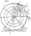
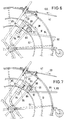
- FIGS 5 to 8 show another embodiment the device according to the invention in the basic construction essentially with the embodiment according to Figures 1 to 4 matches, so that for the same or parts with the same effect use the same reference numerals have been and the previous description analogously also applies to this embodiment.
- the difference between the two embodiments is in the main thing in the different drive.
- Embodiment according to Figures 5 to 8 has the Drive an electric gear motor 87, which is optional to a power grid, an accumulator or to a emergency power generators usually available on construction sites can be connected.
- the electric gear motor instead of the hand crank in the embodiment be grown according to Figures 1 to 4, so that it with the corresponding chain drives would work.
- An electric motor would have to be selected in the exemplary embodiment, which is switchable in the running direction and which with a adjustable slip clutch is provided to prevent that impermissibly high forces on the flexible rod 42nd be exercised.
- FIG. 5 Friction wheel 88 in a neutral position. If the swivel lever 84 pivoted upward in the direction of arrow 89 the friction wheel comes into contact with the outer cylinder ring 91.
- Spokes 102, 103 of the reel wheel 2 are designed differently and arranged as comparatively according to Figure 2, namely the spokes 102, 103 parallel to each other, are on fixed inner end on a circumferential bearing bush 105, which in turn on a fixed axis 104 sits.
- the upper ends of the spokes 102, 103 are on the inner sides of the abutments 40 attached so that in particular sufficient in addition to the spoke 102 on the outside Space for the arrangement of the cylindrical rings 91 and 92 remains.
- the outer cylinder ring 91 is on the Bottom of the attachment pieces 40 attached during the inner cylinder ring 92 attached to spoke-like supports 106, e.g. is welded on.
- Figure 8 also shows that in addition to the electric motor drive on the other side of the reel wheel 2, a hand crank drive can be provided can, which operates as an alternative to the electric motor drive can be. But when the electric motor drive is actuated must in any case to avoid the risk of injury the crank handle 46 is removed with the handle 47 become.
Landscapes
- Storing, Repeated Paying-Out, And Re-Storing Of Elongated Articles (AREA)
Description
Claims (21)
- Vorrichtung zum Speichern sowie zum Auf- und Abwickeln eines flexiblen, biegsamen Stabes (42) für das Einziehen von Kabeln in Kabelschutzrohre, mit einem auf einer Drehachse (16) eines Gestells (1) drehbar gelagerten, zwei Hälften aufweisenden Haspelrad (2), welches Haspelrad (2) von der Drehachse ausgehend radial verlaufende Haspelradspeichen (17, 18) aufweist und an seinem äußeren Umfang einen umlaufenden Spalt hat, in dem ein feststehender Ring (26) mit einer Auslaßöffnung (67) für den Stab (42) angeordnet ist, dadurch gekennzeichnet,daß die Speichen (17, 18) der beiden Hälften des in dem Gestell (1) gelagerten Haspelrades (2) am äußeren Umfang des Haspelrades (2) aufeinander zu umgebogen sind, so daß sich der Stab (42) auf der Innenseite in Windungen (43) anlegt,daß das Haspelrad (2) einen auf die Drehachse (16) wirkenden Antrieb (46, 47, 50, 51, 52) aufweist und daß die beiden Hälften des Haspelrades (2) über innere Anlagestücke (40) für den Stab (42) unlösbar miteinander verbunden sind, welche Anlagestücke (40) zwischen den einzelnen, einander gegenüberliegenden Haspelradspeichen (17, 18) mit Abstand vom äußeren Umfang des Haspelrades (2) befestigt sind.
- Vorrichtung nach Anspruch 1, dadurch gekennzeichnet, daß die äußeren Enden der Haspelradspeichen (17, 18) an Ringen (24, 25) befestigt sind, welche sich mit Spiel zu beiden Seiten des feststehenden Ringes (26) befinden.
- Vorrichtung nach Anspruch 1 oder 2, dadurch gekennzeichnet, daß die Auslaßöffnung (67) im Bereich des oberen Scheitels des Haspelrades (2) vorgesehen ist.
- Vorrichtung nach einem der vorhergehenden Ansprüche, dadurch gekennzeichnet, daß die Anlagestücke (40) leicht nach außen gebogen oder geknickt sind.
- Vorrichtung nach einem der vorhergehenden Ansprüche, dadurch gekennzeichnet, daß der Antrieb eine Handkurbel (46, 47) aufweist, welche in dem Gestell (1) gelagert ist und welche über Kettenräder (50, 52) und mittels einer Kette (51) mit der Drehachse (16) des Haspelrades (2) verbunden ist.
- Vorrichtung nach Anspruch 5, dadurch gekennzeichnet, daß auf beiden Seiten des Haspelrades (2) Kettenräder (50, 52; 54, 56) mit unterschiedlichen Untersetzungsverhältnissen und entsprechenden Ketten (51, 55) vorgesehen sind.
- Vorrichtung nach Anspruch 6, dadurch gekennzeichnet, daß die Handkurbel (46, 47) mittels einer Aufsteckmuffe (48) leicht aufsteckbar und abnehmbar ist.
- Vorrichtung nach einem der vorhergehenden Ansprüche, dadurch gekennzeichnet, daß der feststehende Ring (26) an mindestens drei Stellen (59, 64, 70, 80) auf dem Umfang des Haspelrades (2) mit dem Gestell (1) fest verbunden ist.
- Vorrichtung nach einem der vorhergehenden Ansprüche, dadurch gekennzeichnet, daß die Auslaßöffnung (67) für den Stab (42) durch gegenseitige keilförmige Abschrägungen (68, 69) der unterbrochenen Enden des feststehenden Ringes (26) gebildet ist.
- Vorrichtung nach einem der vorhergehenden Ansprüche, dadurch gekennzeichnet, daß im Bereich der Auslaßöffnung (67) eine Andrückrolle (76) vorgesehen ist, welche an dem Stab (42) anliegt.
- Vorrichtung nach Anspruch 10, dadurch gekennzeichnet, daß die Andrückrolle (76) mit einem Längenzählwerk versehen oder verbunden ist.
- Vorrichtung nach einem der vorhergehenden Ansprüche, dadurch gekennzeichnet, daß mit möglichst geringem Abstand von der Auslaßöffnung (67) eine Stabführung (81) mit einem Verbindungsanschluß (82) für einen druck- und zugfesten, biegsamen Führungsschlauch vorgesehen st.
- Vorrichtung nach einem der Ansprüche 1 bis 5 und 7 bis 12, dadurch gekennzeichnet, daß der Antrieb einen Elektrogetriebemotor (87) aufweist, welcher wahlweise an ein Stromnetz, einen Akkumulator oder ein Notstromaggregat anschließbar ist.
- Vorrichtung nach Anspruch 13, dadurch gekennzeichnet, daß der Elektrogetriebemotor (87) mittels einer Konsole (86) an einem Schwenkhebel (84) befestigt ist, welcher seinerseits an einem Gelenk (85) am Gestell (1) gelagert ist, und daß auf der Antriebswelle des Elektrogetriebemotors (87) ein Reibrad (88) sitzt, welches wahlweise entsprechend der gewünschten Drehrichtung (98, 99) des Haspelrades (2) an einem inneren Zylinderring (92) oder an einem äußeren Zylinderring (91) andrückbar ist.
- Vorrichtung nach Anspruch 14, dadurch gekennzeichnet, daß an dem Gestell (1) zu beiden Seiten des Schwenkhebels (84) Federhalter (93, 94) befestigt sind, und daß zwischen den Federhaltern (93, 94) und dem Schwenkhebel (84) Druckfedern (95, 96) eingesetzt sind, die den Schwenkhebel (84) und das Reibrad (88) bei Nichtbetätigung in eine neutrale Mittellage drücken.
- Vorrichtung nach einem der vorhergehenden Ansprüche, dadurch gekennzeichnet, daß das Gestell (1) mit einer Gestellauflage (27) versehen ist, an deren beiden Seiten Aufstellrahmen (28, 29) mit Aufstellplatten (30, 31) schwenkbar angebracht sind.
- Vorrichtung nach einem der vorhergehenden Ansprüche, dadurch gekennzeichnet, daß an dem Gestell (1) unter Zwischenschaltung einer Radachse (38) zwei Laufräder (36, 37) angebracht sind, und daß unter einem Winkel hierzu mindestens ein weiteres Stützrad (63) an dem Gestell (1) derart vorgesehen ist, daß das Stützrad (63) nach Schwenken des Gestells (1) mitsamt des Haspelrades (2) um diesen Winkel in Transportstellung kommt.
- Vorrichtung nach einem der vorhergehenden Ansprüche, dadurch gekennzeichnet, daß das Gestell (1) ein einstückiges Rohr (3) aufweist, welches zu beiden Seiten des Haspelrades (2) etwa Z-förmig gebogen ist, mit waagerechten unteren Rohrteilen (5), schräg aufwärts gerichteten Rohrteilen (6), Zwischenrohrteilen (7), weiteren schräg aufwärts gerichteten Rohrteilen (8) und einem oberen Rohrbogen (9).
- Vorrichtung nach Anspruch 18, dadurch gekennzeichnet, daß das Gestell (1) zwei weitere Rohre (4) zu beiden Seiten des Haspelrades (2) aufweist, mit jeweils einem unteren waagerechten Rohrteil (10), einem schräg aufwärts gerichteten Rohrteil (11), einem abgebogenen schräg aufwärts gerichteten Rohrteil (12) und einem Endbogen (13), welcher an dem Rohrteil (8) des Rohres (3) befestigt ist.
- Vorrichtung nach Anspruch 18 und 19, dadurch gekennzeichnet, daß an den im wesentlichen parallel zueinander verlaufenden Rohrteilen (7, 11) der Rohre (3, 4) Achslagerplatten (14, 15) für die Lager der Drehachse (16) des Haspelrades befestigt sind.
- Vorrichtung nach einem der Ansprüche 18 bis 20, dadurch gekennzeichnet, daß zwischen den im wesentlichen parallel Zueinander verlaufenden Rohrteilen (8, 12) der Rohre (3, 4) die Kurbellager (49) angeordnet sind.
Priority Applications (3)
| Application Number | Priority Date | Filing Date | Title |
|---|---|---|---|
| DE59407745T DE59407745D1 (de) | 1994-04-19 | 1994-04-19 | Vorrichtung zum Speichern sowie zum Auf- und Abwickeln eines flexiblen, biegsamen Stabes |
| AT94106111T ATE176212T1 (de) | 1994-04-19 | 1994-04-19 | Vorrichtung zum speichern sowie zum auf- und abwickeln eines flexiblen, biegsamen stabes |
| EP94106111A EP0687642B1 (de) | 1994-04-19 | 1994-04-19 | Vorrichtung zum Speichern sowie zum Auf- und Abwickeln eines flexiblen, biegsamen Stabes |
Applications Claiming Priority (1)
| Application Number | Priority Date | Filing Date | Title |
|---|---|---|---|
| EP94106111A EP0687642B1 (de) | 1994-04-19 | 1994-04-19 | Vorrichtung zum Speichern sowie zum Auf- und Abwickeln eines flexiblen, biegsamen Stabes |
Publications (2)
| Publication Number | Publication Date |
|---|---|
| EP0687642A1 EP0687642A1 (de) | 1995-12-20 |
| EP0687642B1 true EP0687642B1 (de) | 1999-01-27 |
Family
ID=8215878
Family Applications (1)
| Application Number | Title | Priority Date | Filing Date |
|---|---|---|---|
| EP94106111A Expired - Lifetime EP0687642B1 (de) | 1994-04-19 | 1994-04-19 | Vorrichtung zum Speichern sowie zum Auf- und Abwickeln eines flexiblen, biegsamen Stabes |
Country Status (3)
| Country | Link |
|---|---|
| EP (1) | EP0687642B1 (de) |
| AT (1) | ATE176212T1 (de) |
| DE (1) | DE59407745D1 (de) |
Families Citing this family (5)
| Publication number | Priority date | Publication date | Assignee | Title |
|---|---|---|---|---|
| DE19605410C2 (de) * | 1996-02-14 | 1998-05-14 | Katimex Cielker Gmbh | Vorrichtung zum Aufnehmen und Abziehen eines biegeelastischen, strangförmigen Materials |
| DE19743085C2 (de) * | 1997-09-30 | 2002-06-13 | Werner Quest | Abwickelvorrichtung für Kabelringe |
| DE10114630C1 (de) * | 2001-03-23 | 2002-10-10 | Bernhard Kummert | Haspel zur Speicherung eines biegsamen Stabelements |
| FR3002217B1 (fr) * | 2013-02-18 | 2015-03-27 | Telenco Networks | Dispositif pour enrouler / derouler un objet allonge |
| CN107088285A (zh) * | 2017-06-09 | 2017-08-25 | 张小龙 | 一种消防水带收回装置 |
Family Cites Families (3)
| Publication number | Priority date | Publication date | Assignee | Title |
|---|---|---|---|---|
| US2913222A (en) * | 1955-06-09 | 1959-11-17 | Kuzara Joseph | Fish tape reel |
| DE1911053U (de) * | 1965-01-13 | 1965-03-04 | Maschb Hafenhuette Peter Lanci | Stahlbandhaspel. |
| EP0403671A1 (de) * | 1989-06-20 | 1990-12-27 | Katimex Cielker Gmbh | Vorrichtung zum Auf- und Abwickeln von Strangmaterial |
-
1994
- 1994-04-19 EP EP94106111A patent/EP0687642B1/de not_active Expired - Lifetime
- 1994-04-19 AT AT94106111T patent/ATE176212T1/de not_active IP Right Cessation
- 1994-04-19 DE DE59407745T patent/DE59407745D1/de not_active Expired - Fee Related
Also Published As
| Publication number | Publication date |
|---|---|
| DE59407745D1 (de) | 1999-03-11 |
| ATE176212T1 (de) | 1999-02-15 |
| EP0687642A1 (de) | 1995-12-20 |
Similar Documents
| Publication | Publication Date | Title |
|---|---|---|
| EP1584593B1 (de) | Abrollvorrichtung für Ringbunde | |
| DE102009040200B4 (de) | Transportvorrichtung für ein längliches Objekt | |
| DE102011107239B3 (de) | Spulgerät zum Verlegen von Rohren und Kabeln | |
| EP2324200A2 (de) | Verfahren und vorrichtung zum auskleiden von tunnelwänden bzw. tunneldecken mit schutznetzen | |
| EP3924289B1 (de) | Kran sowie kabeltrommeleinheit hierfür | |
| DE2822466A1 (de) | Rollenanordnung zum aufbewahren, zufuehren und auf- bzw. abwickeln langgestreckter materialien | |
| DE2941046A1 (de) | Bewaesserungsvorrichtung fuer landwirtschaftliche beregnungsanlagen | |
| EP2570374A2 (de) | Haspel zum Auf- und Abwickeln von langgestreckten Materialien und Haspelanlage mit zumindest einer solchen Haspel oder für zumindest eine solche Haspel | |
| DE2424043A1 (de) | Rohrbuendelschluessel | |
| DE2545096A1 (de) | Bohranlage bzw. bohrgestell, insbesondere bewegbare(s), selbstangetriebene(s) bohranlage bzw. bohrgestell mit einem transportablen, teleskopartig ineinanderschiebbaren mast | |
| DE69406934T2 (de) | Kabeltrommelgestell | |
| EP4046925A2 (de) | Vorrichtung zum halten und abziehen einer folie | |
| EP0687642A1 (de) | Vorrichtung zum Speichern sowie zum Auf- und Abwickeln eines flexiblen, biegsamen Stabes | |
| DE20208740U1 (de) | Teleskopausleger eines Krans | |
| DE3014724C2 (de) | Auf- und Abziehvorrichtung für Planen von Großzelten | |
| DE2512619A1 (de) | Seilwinde | |
| EP0226571A2 (de) | Schneekette | |
| DE102017000009B4 (de) | Abspannvorrichtung für einen Ausleger eines Krans | |
| DE2647535A1 (de) | Kranaufbau | |
| DE4327860C1 (de) | Vorrichtung zur drehenden Lagerung einer Kabeltrommel | |
| DE102008036351B4 (de) | Gurtaufwickler | |
| DE2605101C2 (de) | Vorrichtung zum Antrieb einer Maschine | |
| DE2620668C3 (de) | Vorrichtung zur Höhenverstellung von Stützen für Schalungsgerüste o.dgl. | |
| DE2840061C2 (de) | Zuführungs- und/oder Haltevorrichtung | |
| DE102025117083A1 (de) | Abrollvorrichtung für Ringbunde von Fernwärmerohren und dergleichen |
Legal Events
| Date | Code | Title | Description |
|---|---|---|---|
| PUAI | Public reference made under article 153(3) epc to a published international application that has entered the european phase |
Free format text: ORIGINAL CODE: 0009012 |
|
| 17P | Request for examination filed |
Effective date: 19950522 |
|
| AK | Designated contracting states |
Kind code of ref document: A1 Designated state(s): AT BE CH DE DK ES FR GB GR IE IT LI LU MC NL PT SE |
|
| 17Q | First examination report despatched |
Effective date: 19961127 |
|
| GRAG | Despatch of communication of intention to grant |
Free format text: ORIGINAL CODE: EPIDOS AGRA |
|
| GRAG | Despatch of communication of intention to grant |
Free format text: ORIGINAL CODE: EPIDOS AGRA |
|
| GRAH | Despatch of communication of intention to grant a patent |
Free format text: ORIGINAL CODE: EPIDOS IGRA |
|
| GRAH | Despatch of communication of intention to grant a patent |
Free format text: ORIGINAL CODE: EPIDOS IGRA |
|
| GRAA | (expected) grant |
Free format text: ORIGINAL CODE: 0009210 |
|
| AK | Designated contracting states |
Kind code of ref document: B1 Designated state(s): AT BE CH DE DK ES FR GB GR IE IT LI LU MC NL PT SE |
|
| PG25 | Lapsed in a contracting state [announced via postgrant information from national office to epo] |
Ref country code: SE Free format text: THE PATENT HAS BEEN ANNULLED BY A DECISION OF A NATIONAL AUTHORITY Effective date: 19990127 Ref country code: NL Free format text: LAPSE BECAUSE OF FAILURE TO SUBMIT A TRANSLATION OF THE DESCRIPTION OR TO PAY THE FEE WITHIN THE PRESCRIBED TIME-LIMIT Effective date: 19990127 Ref country code: IT Free format text: LAPSE BECAUSE OF FAILURE TO SUBMIT A TRANSLATION OF THE DESCRIPTION OR TO PAY THE FEE WITHIN THE PRE;WARNING: LAPSES OF ITALIAN PATENTS WITH EFFECTIVE DATE BEFORE 2007 MAY HAVE OCCURRED AT ANY TIME BEFORE 2007. THE CORRECT EFFECTIVE DATE MAY BE DIFFERENT FROM THE ONE RECORDED.SCRIBED TIME-LIMIT Effective date: 19990127 Ref country code: GR Free format text: LAPSE BECAUSE OF NON-PAYMENT OF DUE FEES Effective date: 19990127 Ref country code: ES Free format text: THE PATENT HAS BEEN ANNULLED BY A DECISION OF A NATIONAL AUTHORITY Effective date: 19990127 |
|
| REF | Corresponds to: |
Ref document number: 176212 Country of ref document: AT Date of ref document: 19990215 Kind code of ref document: T |
|
| REG | Reference to a national code |
Ref country code: CH Ref legal event code: EP |
|
| REG | Reference to a national code |
Ref country code: IE Ref legal event code: FG4D Free format text: GERMAN |
|
| REF | Corresponds to: |
Ref document number: 59407745 Country of ref document: DE Date of ref document: 19990311 |
|
| REG | Reference to a national code |
Ref country code: CH Ref legal event code: NV Representative=s name: HEPP, WENGER & RYFFEL AG |
|
| RAP2 | Party data changed (patent owner data changed or rights of a patent transferred) |
Owner name: KATIMEX CIELKER GMBH |
|
| RIN2 | Information on inventor provided after grant (corrected) |
Free format text: CIELKER, WERNER |
|
| ET | Fr: translation filed | ||
| PG25 | Lapsed in a contracting state [announced via postgrant information from national office to epo] |
Ref country code: LU Free format text: LAPSE BECAUSE OF NON-PAYMENT OF DUE FEES Effective date: 19990419 |
|
| PG25 | Lapsed in a contracting state [announced via postgrant information from national office to epo] |
Ref country code: PT Free format text: LAPSE BECAUSE OF FAILURE TO SUBMIT A TRANSLATION OF THE DESCRIPTION OR TO PAY THE FEE WITHIN THE PRESCRIBED TIME-LIMIT Effective date: 19990427 Ref country code: DK Free format text: LAPSE BECAUSE OF FAILURE TO SUBMIT A TRANSLATION OF THE DESCRIPTION OR TO PAY THE FEE WITHIN THE PRESCRIBED TIME-LIMIT Effective date: 19990427 |
|
| PG25 | Lapsed in a contracting state [announced via postgrant information from national office to epo] |
Ref country code: BE Free format text: LAPSE BECAUSE OF NON-PAYMENT OF DUE FEES Effective date: 19990430 |
|
| GBT | Gb: translation of ep patent filed (gb section 77(6)(a)/1977) |
Effective date: 19990504 |
|
| NLT2 | Nl: modifications (of names), taken from the european patent patent bulletin |
Owner name: KATIMEX CIELKER GMBH |
|
| NLV1 | Nl: lapsed or annulled due to failure to fulfill the requirements of art. 29p and 29m of the patents act | ||
| PG25 | Lapsed in a contracting state [announced via postgrant information from national office to epo] |
Ref country code: IE Free format text: LAPSE BECAUSE OF NON-PAYMENT OF DUE FEES Effective date: 19990820 |
|
| REG | Reference to a national code |
Ref country code: IE Ref legal event code: FD4D |
|
| BERE | Be: lapsed |
Owner name: CIELKER WERNER Effective date: 19990430 |
|
| PG25 | Lapsed in a contracting state [announced via postgrant information from national office to epo] |
Ref country code: MC Free format text: LAPSE BECAUSE OF NON-PAYMENT OF DUE FEES Effective date: 19991031 |
|
| PLBE | No opposition filed within time limit |
Free format text: ORIGINAL CODE: 0009261 |
|
| STAA | Information on the status of an ep patent application or granted ep patent |
Free format text: STATUS: NO OPPOSITION FILED WITHIN TIME LIMIT |
|
| 26N | No opposition filed | ||
| REG | Reference to a national code |
Ref country code: GB Ref legal event code: IF02 |
|
| PGFP | Annual fee paid to national office [announced via postgrant information from national office to epo] |
Ref country code: GB Payment date: 20050411 Year of fee payment: 12 |
|
| PGFP | Annual fee paid to national office [announced via postgrant information from national office to epo] |
Ref country code: FR Payment date: 20050419 Year of fee payment: 12 |
|
| PGFP | Annual fee paid to national office [announced via postgrant information from national office to epo] |
Ref country code: AT Payment date: 20050421 Year of fee payment: 12 |
|
| PGFP | Annual fee paid to national office [announced via postgrant information from national office to epo] |
Ref country code: CH Payment date: 20050422 Year of fee payment: 12 |
|
| PGFP | Annual fee paid to national office [announced via postgrant information from national office to epo] |
Ref country code: DE Payment date: 20050621 Year of fee payment: 12 |
|
| PG25 | Lapsed in a contracting state [announced via postgrant information from national office to epo] |
Ref country code: GB Free format text: LAPSE BECAUSE OF NON-PAYMENT OF DUE FEES Effective date: 20060419 Ref country code: AT Free format text: LAPSE BECAUSE OF NON-PAYMENT OF DUE FEES Effective date: 20060419 |
|
| PG25 | Lapsed in a contracting state [announced via postgrant information from national office to epo] |
Ref country code: LI Free format text: LAPSE BECAUSE OF NON-PAYMENT OF DUE FEES Effective date: 20060430 Ref country code: CH Free format text: LAPSE BECAUSE OF NON-PAYMENT OF DUE FEES Effective date: 20060430 |
|
| PG25 | Lapsed in a contracting state [announced via postgrant information from national office to epo] |
Ref country code: DE Free format text: LAPSE BECAUSE OF NON-PAYMENT OF DUE FEES Effective date: 20061101 |
|
| REG | Reference to a national code |
Ref country code: CH Ref legal event code: PL |
|
| GBPC | Gb: european patent ceased through non-payment of renewal fee |
Effective date: 20060419 |
|
| REG | Reference to a national code |
Ref country code: FR Ref legal event code: ST Effective date: 20061230 |
|
| PG25 | Lapsed in a contracting state [announced via postgrant information from national office to epo] |
Ref country code: FR Free format text: LAPSE BECAUSE OF NON-PAYMENT OF DUE FEES Effective date: 20060502 |