EP0687644A2 - Aufhängevorrichtung eines hydraulischen Aufzugs - Google Patents
Aufhängevorrichtung eines hydraulischen Aufzugs Download PDFInfo
- Publication number
- EP0687644A2 EP0687644A2 EP95109091A EP95109091A EP0687644A2 EP 0687644 A2 EP0687644 A2 EP 0687644A2 EP 95109091 A EP95109091 A EP 95109091A EP 95109091 A EP95109091 A EP 95109091A EP 0687644 A2 EP0687644 A2 EP 0687644A2
- Authority
- EP
- European Patent Office
- Prior art keywords
- diverting pulley
- elevator
- piston
- rope
- cylinder
- Prior art date
- Legal status (The legal status is an assumption and is not a legal conclusion. Google has not performed a legal analysis and makes no representation as to the accuracy of the status listed.)
- Granted
Links
Images


Classifications
-
- B—PERFORMING OPERATIONS; TRANSPORTING
- B66—HOISTING; LIFTING; HAULING
- B66B—ELEVATORS; ESCALATORS OR MOVING WALKWAYS
- B66B11/00—Main component parts of lifts in, or associated with, buildings or other structures
- B66B11/04—Driving gear ; Details thereof, e.g. seals
- B66B11/08—Driving gear ; Details thereof, e.g. seals with hoisting rope or cable operated by frictional engagement with a winding drum or sheave
-
- B—PERFORMING OPERATIONS; TRANSPORTING
- B66—HOISTING; LIFTING; HAULING
- B66B—ELEVATORS; ESCALATORS OR MOVING WALKWAYS
- B66B9/00—Kinds or types of lifts in, or associated with, buildings or other structures
- B66B9/04—Kinds or types of lifts in, or associated with, buildings or other structures actuated pneumatically or hydraulically
Definitions
- the present invention relates to a suspension arrangement for a hydraulic elevator as defined in the preamble of claim 1.
- conventional hydraulic elevators are implemented as rucksack-type elevators in which the elevator car is mounted on a supporting frame resembling a rucksack.
- these elevators are either of a direct-acting or an indirect-acting type.
- Direct-acting elevators of normal construction without an expensive telescopic cylinder are only applicable in low-rise buildings where the elevator only serves one or two floors. Therefore, most hydraulic elevators employ an indirect-acting type of suspension.
- Such elevators usually have a hoisting height of 3.5-15 m, corresponding to 2-6 floors. The maximum hoisting height is about 20 m.
- a hoisting rope attached to a fixed column is passed over a diverting pulley mounted on top of the piston and further to the car frame supporting the elevator car. Due to this roping, the car travel equals twice the stroke of the piston, which is why this type of suspension is termed 2:1 suspension.
- the cylinder When larger hoisting heights are to be achieved, the cylinder has to be hoisted into the shaft via the top of the shaft. However, this is only possible at an early stage of the construction work, and it is necessary to schedule the transport and hoisting of the cylinder into the shaft accordingly. This causes extra work and expenses. Moreover, the cylinder has to be protected in the shaft during construction, and it is always more or less of a hindrance to other work.
- the object of the present invention is to achieve a suspension arrangement for a hydraulic elevator that allows quick and simple installation of the hydraulic elevator and permits advantageous use of large hoisting heights.
- the above-mentioned drawbacks of known solutions are eliminated.
- the suspension arrangement of the invention is characterized by what is presented in the characterization part of claim 1.
- the invention provides the advantage that, using a cylinder length (about 5 m) that is optimal in view of transport and handling of the cylinder, hoisting heights one and half times or even twice as large as in the case of the present 2:1 suspension, i.e. a height of about 15- 22 m can be achieved.
- a further advantage is that, as a short cylinder is used, buckling of the piston is no longer a decisive factor in the dimensioning but the piston is always dimensioned according to the pressure. This means e.g. that, for each piston size, only one piston tube wall thickness is required, thus reducing the number of different cylinder assemblies needed.
- the suspension arrangement of the invention makes it possible to use a cylinder system in which the maximum cylinder length is only 5.5 m and the cylinder is mounted directly on an elevator guide rail, permitting serial production of cylinders for different lengths, e.g. at 0.25 m intervals.
- the cylinders have to be manufactured specifically for each elevator for different lengths from 3 m to 11 m, with possible extensions. For this reason, current arrangements involve difficult problems for the rationalization of manufacture and the delivery process as a whole.
- the whole extended hoisting height range of the hydraulic elevator can now be optimally implemented using the following system. Hoisting height H ⁇ 3.5 m suspension 1:1 H ⁇ 11 m suspension 2:1 (present) H ⁇ 16.5 m suspension 3:1 H ⁇ 22 m suspension 4:1
- Yet another advantage is that, as the weight of the piston tube is minimized due to the reduced wall thickness and tube length, a larger useful load of the elevator can be achieved than in previously known solutions.
- FIG. 1 shows the upper end of an elevator shaft in lateral view. Of the elevator and shaft equipment, only the essential, most important elements with regard to the invention are shown.
- the elevator car 1 together with the car frame 4,15,19,23 moves along vertical guide rails 2 which are fixed to the bottom of the shaft.
- the guide rails are secured to a shaft wall by means of rail fixing brackets 14 placed at certain distances from each other.
- the suspension of the elevator car is of the so- called rucksack type, which in this context means that the elevator car is not directly supported by the guide rails 2 but instead by a car frame moving along the guide rails and comprising a bottom beam 4 placed near the first side wall of the elevator shaft (in Fig. 2 and 6, the removed wall on the side facing towards the viewer, and in Fig.
- the distance between the supporting beams 19 is suitably shorter than the distance between the guide rails 2.
- the other ends of the supporting beams are attached to the lower ends of essentially upright vertical beams 15 extending upwards to a height suitably exceeding the height of the elevator car.
- the upper ends of the vertical beams are connected to each other by an overhead beam 23 placed essentially above the elevator car, the elevator car being fixed by its upper part to the overhead beam 23.
- the vertical beam 15 and the supporting beam 19 in the arrangement illustrated by the figure form a car supporter having the shape of letter L facing left, the elevator car being mounted on the supporting beams 19.
- the car frame is supported on the guide rails by means of guide rollers 18 running on the guide surface facing towards the elevator car.
- guide rollers 17 running along the opposite guide surface as compared to the lower guide rollers. This arrangement prevents the car frame from overturning sideways from the guide rail.
- the hydraulic cylinder 5 is immovably mounted directly on the elevator guide rails 2 by means of a cylinder supporter 6 provided with a projecting base 34 carrying the cylinder.
- a cylinder supporter 6 provided with a projecting base 34 carrying the cylinder.
- This solution obviates the need to use a separate supporting pillar, which, normally extending from the lower end of the hydraulic cylinder to the bottom of the shaft, would be very long and expensive.
- the cylinder supporter 6 is attached to the guide rails by means of rail clips and bolts. The cylinder force is transmitted by the guide rails to the bottom of the shaft.
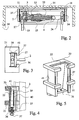
- a holding device 26 as illustrated by Fig. 3, 4 and 5 is used.
- the frame of the holding device which consists of a hollow wedge-shaped socket 22, 27, 41 tapering upwards, reinforcements 20, 21 bracing the socket and a supporting bar 36 at the lower end of the socket, is placed around the back of the guide rail so as to leave a free space for the elevator between the guide rails.
- the frame and the reinforcements 21, 21 are open on the side facing towards the guide rail, so that, as the back of the guide rail is inside the frame of the holding device, the guiding part of the rail remains outside.
- the frame has essentially the shape of a rectangular letter C in which the inclined back wall 22 is perpendicular to each of the straight side walls 41 at the edges.
- the two front walls Starting at the front edge of each side wall there is a narrow front wall 27 in a position slightly turned out, the two front walls being essentially directed towards each other.
- the front walls are not exactly perpendicular to the side walls, but the slant of the front walls corresponds to the slant of the back of the guide rail.
- the opening of the C-shaped frame said opening extending through the whole height of the frame, through which opening the guiding part of the guide rail protrudes from inside the frame of the holding device.
- the supporting bar 36 at the bottom of the holding device, which connects the two side walls, is provided at its middle with a threaded hole for a tightening screw 37. Moreover, on each side of the threaded hole there is one unthreaded hole for screws 38 for releasing the wedge 39.
- the wedge 39 placed inside the frame of the holding device is correspondingly provided with threaded holes for the release screws.
- the wedge 39 itself is a body of a width nearly equal to the width of the space inside the frame, tapering upwards in its lateral dimension. The wedge is mounted between the slanting back wall 22 of the frame and the rear surface of the back of the guide rail.
- the straight front surface of the wedge which is pressed against the rear surface of the back of the guide rail, is provided with two parallel cutouts, each of which accommodates a serrated arrester 40 whose serrations are pressed against the rear surface of the back of the guide rail when the wedge is tightened in place by means of the tightening screw 37.
- One holding device 26 is provided for each guide rail. After the holding devices have been tightened on the guide rails, the cylinder supporter 6 can be lowered onto the holding devices.
- the cylinder itself is fixed with screws onto the projecting base 34 of the cylinder supporter.
- the wedge is released from its tightened condition by means of the release screws 38.
- a piston 7 which is provided with a diverting pulley unit mounted on the upper end of the piston, comprising a frame 25 and sliding guides 24 mounted on its upper part, one for each guide rail 2.
- a horizontally adjustable adapter 13 mounted on the lower part of the frame.
- the adapter allows the ropes to be so attached to cylinders of different sizes that the effect of the rope force can easily be centered in relation to the piston.
- a diverting pulley 8 rotatably mounted on the frame. As the piston moves vertically, the guides 24 slide along the rails 2, keeping the upper end of the piston horizontally steady.
- the first ends of the elevator ropes 3 are attached to a rope anchorage 11 in the car frame, from where they are passed via the diverting pulley 8 mounted on the piston 7 and around the additional diverting pulley 9 at the lower end of the cylinder 5 and further up to the adapter 13 attached to the diverting pulley unit on the piston. It follows from this suspension that when the piston moves through a distance of one unit of measure, the elevator car moves through a distance of three units of measure, so this suspension can be termed 3:1 suspension.
- a feature essential to the solution of the invention is that the positions of the diverting pulley 9 on the top end of the piston and the point of rope attachment on the adapter 13 relative to each other are so selected that the resultant of the forces transmitted through them to the piston end is applied to the end of the piston 7 completely centrically without generating a bending moment. Therefore, the diverting pulley 8 lies horizontally eccentrically on the piston 7 and the rope attachment point on the adapter 13 lies horizontally on the opposite side of the midline of the piston 7 in relation to the midline of the diverting pulley 8. It is also important that the additional diverting pulley 9 at the bottom end of the cylinder has a smaller diameter than the diverting pulley 8 on top of the piston.
- the additional diverting pulley 9 at the lower end is horizontally eccentrically placed in relation to the midline of the cylinder.
- the direction of eccentricity is the same.
- the position of the rope anchorage 11 on the car frame is so chosen that the anchorage lies at a sufficient horizontal distance from the ropes running from the additional diverting pulley 9 to the point of rope attachment on the adapter 13. This distance is sufficient if, when the elevator is moving, the rope anchorage 11 passes the additional diverting pulley 9 at a distance considered sufficient. Because of this passing, it is essential that the additional diverting pulley 9 at the lower end should have a smaller diameter than the diverting pulley 8 on the top end and that it should be eccentrically mounted, as mentioned above.
- the suspension ratio could be 4:1, which is the case in the elevators illustrated by Fig. 6 and 7.
- the passage and points of attachment of the elevator ropes differ from 3:1 suspension.
- the top end of the piston is provided with two diverting pulleys placed side by side.
- the first ends of the ropes are attached to a rope anchorage 11 in the car frame, from where the ropes are passed via a first diverting pulley 28 mounted on the top end of the piston and around an additional diverting pulley 9 at the lower end of the cylinder 5 and further up to a second diverting pulley 29 at the top end of the piston and then down to an anchorage 30 on the mounting of the lower end of the cylinder.
- all diverting pulleys 9, 28 and 29 are centrically placed in relation to the midline of the cylinder 5 and piston 7.
- the second diverting pulley 29 on the top end has a smaller diameter than the first diverting pulley 28 on the top end.
- 4:1 suspension provides the same advantages as 3:1 suspension and a 5-m cylinder length allows a hoisting height of 22 m to be achieved, which is sufficient to cover the entire range of elevators at present implemented e.g. as so-called side-drive rope-driven elevators with machine room below. At present, this elevator type competes directly with the hydraulic elevator.
Landscapes
- Engineering & Computer Science (AREA)
- Structural Engineering (AREA)
- Civil Engineering (AREA)
- Mechanical Engineering (AREA)
- Automation & Control Theory (AREA)
- Types And Forms Of Lifts (AREA)
- Lift-Guide Devices, And Elevator Ropes And Cables (AREA)
- Vehicle Body Suspensions (AREA)
- Fluid-Pressure Circuits (AREA)
- Transplanting Machines (AREA)
- Reciprocating Pumps (AREA)
- Forklifts And Lifting Vehicles (AREA)
- Valve Device For Special Equipments (AREA)
Applications Claiming Priority (2)
| Application Number | Priority Date | Filing Date | Title |
|---|---|---|---|
| FI942820 | 1994-06-14 | ||
| FI942820A FI100962B (fi) | 1994-06-14 | 1994-06-14 | Hydraulihissin ripustusjärjestely |
Publications (3)
| Publication Number | Publication Date |
|---|---|
| EP0687644A2 true EP0687644A2 (de) | 1995-12-20 |
| EP0687644A3 EP0687644A3 (de) | 1996-07-31 |
| EP0687644B1 EP0687644B1 (de) | 2002-02-06 |
Family
ID=8540914
Family Applications (1)
| Application Number | Title | Priority Date | Filing Date |
|---|---|---|---|
| EP95109091A Expired - Lifetime EP0687644B1 (de) | 1994-06-14 | 1995-06-13 | Aufhängevorrichtung eines hydraulischen Aufzugs |
Country Status (9)
| Country | Link |
|---|---|
| US (1) | US5653311A (de) |
| EP (1) | EP0687644B1 (de) |
| JP (1) | JP3734851B2 (de) |
| CN (1) | CN1053162C (de) |
| AT (1) | ATE212948T1 (de) |
| BR (1) | BR9502805A (de) |
| DE (1) | DE69525285T2 (de) |
| ES (1) | ES2171173T3 (de) |
| FI (1) | FI100962B (de) |
Cited By (2)
| Publication number | Priority date | Publication date | Assignee | Title |
|---|---|---|---|---|
| WO1998000358A1 (fr) * | 1996-07-02 | 1998-01-08 | Emile Kadoche | Dispositif d'entrainement pour ascenseur |
| CN1077083C (zh) * | 1996-10-28 | 2002-01-02 | 奥蒂斯电梯公司 | 带有配重的液压电梯 |
Families Citing this family (9)
| Publication number | Priority date | Publication date | Assignee | Title |
|---|---|---|---|---|
| US6085872A (en) * | 1998-03-25 | 2000-07-11 | Thyssen Elevator Holding Corporation | Roped hydraulic elevator |
| US6179094B1 (en) | 1998-04-24 | 2001-01-30 | Montgomery Kone, Inc. | Hydraulic elevator with plunger brakes |
| SG75168A1 (en) * | 1998-05-08 | 2000-09-19 | Inventio Ag | Hydraulic elevator |
| US6659231B2 (en) * | 2002-03-12 | 2003-12-09 | Inventio Ag | Self-balancing synchronization assembly for a hydraulic elevator |
| KR100860935B1 (ko) * | 2004-06-07 | 2008-09-29 | 오티스 엘리베이터 컴파니 | 기계실이 없는 엘리베이터 시스템 |
| WO2013182209A1 (en) | 2012-06-05 | 2013-12-12 | Soliman Mohamed Abdel Hameed Abdel Alleem Mohamed | Advanced roped hydraulic elevator with and without counterweight for all heights and speeds. |
| KR20180034544A (ko) | 2015-07-27 | 2018-04-04 | 오티스 엘리베이터 컴파니 | 승강기 시스템 레일을 위한 흡수기 |
| CN105197735A (zh) * | 2015-10-23 | 2015-12-30 | 北京安泰鸿源电梯设计有限公司 | 一种轿厢系统 |
| CN106956996A (zh) * | 2017-05-05 | 2017-07-18 | 四川泰升液压电梯制造有限公司 | 一种液压提速电梯 |
Family Cites Families (9)
| Publication number | Priority date | Publication date | Assignee | Title |
|---|---|---|---|---|
| US2627943A (en) * | 1951-11-29 | 1953-02-10 | Shepard Co Lewis | Lifting mechanism |
| DE1531106A1 (de) * | 1967-08-10 | 1969-08-07 | Haushahn Maschinenfabrik C | Hydraulisch betriebener Aufzug |
| GB1438727A (en) * | 1973-12-10 | 1976-06-09 | Sims A F | Hydraulically operated building hoist |
| US4333549A (en) * | 1980-06-25 | 1982-06-08 | Otis Elevator Company | Car blocking apparatus |
| JPS63106289A (ja) * | 1986-10-22 | 1988-05-11 | 株式会社日立製作所 | 流体圧エレベ−タ |
| JPH02261790A (ja) * | 1989-03-31 | 1990-10-24 | Toshiba Corp | 間接式油圧エレベータ |
| JPH038686A (ja) * | 1989-06-05 | 1991-01-16 | Mitsubishi Electric Corp | エレベータ装置 |
| DE4034564A1 (de) * | 1990-10-26 | 1992-04-30 | Bautzen Waggonbau Gmbh | Stuetzlager fuer eine hubeinrichtung, insbesondere fuer reisezug- und gepaeckwagen |
| JP3008686U (ja) | 1994-09-07 | 1995-03-20 | ワン,ミン−ツァン | ゴルフ・バッグの支持用フレーム |
-
1994
- 1994-06-14 FI FI942820A patent/FI100962B/fi not_active IP Right Cessation
-
1995
- 1995-06-06 US US08/471,383 patent/US5653311A/en not_active Expired - Lifetime
- 1995-06-13 EP EP95109091A patent/EP0687644B1/de not_active Expired - Lifetime
- 1995-06-13 AT AT95109091T patent/ATE212948T1/de not_active IP Right Cessation
- 1995-06-13 ES ES95109091T patent/ES2171173T3/es not_active Expired - Lifetime
- 1995-06-13 DE DE69525285T patent/DE69525285T2/de not_active Expired - Lifetime
- 1995-06-14 BR BR9502805A patent/BR9502805A/pt not_active IP Right Cessation
- 1995-06-14 JP JP14697395A patent/JP3734851B2/ja not_active Expired - Lifetime
- 1995-06-14 CN CN95106565A patent/CN1053162C/zh not_active Expired - Lifetime
Non-Patent Citations (1)
| Title |
|---|
| None |
Cited By (4)
| Publication number | Priority date | Publication date | Assignee | Title |
|---|---|---|---|---|
| WO1998000358A1 (fr) * | 1996-07-02 | 1998-01-08 | Emile Kadoche | Dispositif d'entrainement pour ascenseur |
| FR2750687A1 (fr) * | 1996-07-02 | 1998-01-09 | Kadoche Emile | Dispositif d'entrainement pour ascenseur |
| US6148961A (en) * | 1996-07-02 | 2000-11-21 | Kadoche; Emile | Lift driving device |
| CN1077083C (zh) * | 1996-10-28 | 2002-01-02 | 奥蒂斯电梯公司 | 带有配重的液压电梯 |
Also Published As
| Publication number | Publication date |
|---|---|
| FI942820L (fi) | 1995-12-15 |
| FI100962B (fi) | 1998-03-31 |
| US5653311A (en) | 1997-08-05 |
| ES2171173T3 (es) | 2002-09-01 |
| JPH0840672A (ja) | 1996-02-13 |
| CN1118764A (zh) | 1996-03-20 |
| DE69525285T2 (de) | 2002-08-14 |
| BR9502805A (pt) | 1996-01-23 |
| DE69525285D1 (de) | 2002-03-21 |
| EP0687644A3 (de) | 1996-07-31 |
| EP0687644B1 (de) | 2002-02-06 |
| JP3734851B2 (ja) | 2006-01-11 |
| FI942820A0 (fi) | 1994-06-14 |
| CN1053162C (zh) | 2000-06-07 |
| ATE212948T1 (de) | 2002-02-15 |
Similar Documents
| Publication | Publication Date | Title |
|---|---|---|
| CN1099365C (zh) | 补偿钢索装置 | |
| AU737295B2 (en) | Procedure and apparatus for the installation of an elevator | |
| US5020641A (en) | Method and apparatus for erecting hydraulic elevator rails | |
| EP0710618B1 (de) | Antriebsscheibenaufzug | |
| CN106115394B (zh) | 用于在电梯井中对准导轨和层门的装置和方法 | |
| US11365095B2 (en) | Method and an arrangement for installing elevator guide rails into an elevator shaft | |
| US6848543B2 (en) | Single wall interface traction elevator | |
| EP0687644A2 (de) | Aufhängevorrichtung eines hydraulischen Aufzugs | |
| KR20000023059A (ko) | 케이블 단부를 안내 레일에 고정하기 위한 케이블 부착장치를 갖는 견인식 엘리베이터 | |
| US20210316959A1 (en) | Method for installing an elevator system | |
| KR20070037995A (ko) | 승강실 및 승강로에 승강실의 지지 수단을 설치하는 방법 | |
| US6098759A (en) | Hydraulic elevator | |
| JPH05229766A (ja) | エレベーターの昇降体固定装置 | |
| US6659231B2 (en) | Self-balancing synchronization assembly for a hydraulic elevator | |
| US20240017964A1 (en) | Construction elevator arrangement and a method for producing the same | |
| JP2004149291A (ja) | エレベータの乗りかご保持装置 | |
| JP2002060158A (ja) | エレベーターの据付工法 | |
| JP3297345B2 (ja) | 工事用エレベータのガバナロープ繰出し方法 | |
| HK40038218A (en) | A method and an arrangement for installing elevator guide rails into an elevator shaft | |
| JPH08169662A (ja) | エレベーターの吊上装置 | |
| JPH07315710A (ja) | エレベーター | |
| JPH09221281A (ja) | 油圧エレベータ乗かごのかご位置保持装置 |
Legal Events
| Date | Code | Title | Description |
|---|---|---|---|
| PUAI | Public reference made under article 153(3) epc to a published international application that has entered the european phase |
Free format text: ORIGINAL CODE: 0009012 |
|
| AK | Designated contracting states |
Kind code of ref document: A2 Designated state(s): AT BE CH DE DK ES FR GB GR IE IT LI LU MC NL PT SE |
|
| RAX | Requested extension states of the european patent have changed |
Free format text: LT PAYMENT 950629;LV PAYMENT 950629;SI PAYMENT 950629 |
|
| PUAL | Search report despatched |
Free format text: ORIGINAL CODE: 0009013 |
|
| AK | Designated contracting states |
Kind code of ref document: A3 Designated state(s): AT BE CH DE DK ES FR GB GR IE IT LI LU MC NL PT SE |
|
| AX | Request for extension of the european patent |
Free format text: LT PAYMENT 950629;LV PAYMENT 950629;SI PAYMENT 950629 |
|
| 17P | Request for examination filed |
Effective date: 19970131 |
|
| R17P | Request for examination filed (corrected) |
Effective date: 19970131 |
|
| RAP1 | Party data changed (applicant data changed or rights of an application transferred) |
Owner name: KONE CORPORATION |
|
| 17Q | First examination report despatched |
Effective date: 19991227 |
|
| GRAG | Despatch of communication of intention to grant |
Free format text: ORIGINAL CODE: EPIDOS AGRA |
|
| GRAG | Despatch of communication of intention to grant |
Free format text: ORIGINAL CODE: EPIDOS AGRA |
|
| GRAH | Despatch of communication of intention to grant a patent |
Free format text: ORIGINAL CODE: EPIDOS IGRA |
|
| GRAH | Despatch of communication of intention to grant a patent |
Free format text: ORIGINAL CODE: EPIDOS IGRA |
|
| GRAA | (expected) grant |
Free format text: ORIGINAL CODE: 0009210 |
|
| REG | Reference to a national code |
Ref country code: GB Ref legal event code: IF02 |
|
| RIN1 | Information on inventor provided before grant (corrected) |
Inventor name: PELTO-HUIKKO, RAIMO Inventor name: HEIKKINEN, URHO |
|
| AK | Designated contracting states |
Kind code of ref document: B1 Designated state(s): AT BE CH DE DK ES FR GB GR IE IT LI LU MC NL PT SE |
|
| AX | Request for extension of the european patent |
Free format text: LT PAYMENT 19950629;LV PAYMENT 19950629;SI PAYMENT 19950629 |
|
| LTIE | Lt: invalidation of european patent or patent extension | ||
| PG25 | Lapsed in a contracting state [announced via postgrant information from national office to epo] |
Ref country code: NL Free format text: LAPSE BECAUSE OF FAILURE TO SUBMIT A TRANSLATION OF THE DESCRIPTION OR TO PAY THE FEE WITHIN THE PRESCRIBED TIME-LIMIT Effective date: 20020206 Ref country code: LI Free format text: LAPSE BECAUSE OF FAILURE TO SUBMIT A TRANSLATION OF THE DESCRIPTION OR TO PAY THE FEE WITHIN THE PRESCRIBED TIME-LIMIT Effective date: 20020206 Ref country code: GR Free format text: LAPSE BECAUSE OF FAILURE TO SUBMIT A TRANSLATION OF THE DESCRIPTION OR TO PAY THE FEE WITHIN THE PRESCRIBED TIME-LIMIT Effective date: 20020206 Ref country code: CH Free format text: LAPSE BECAUSE OF FAILURE TO SUBMIT A TRANSLATION OF THE DESCRIPTION OR TO PAY THE FEE WITHIN THE PRESCRIBED TIME-LIMIT Effective date: 20020206 Ref country code: BE Free format text: LAPSE BECAUSE OF FAILURE TO SUBMIT A TRANSLATION OF THE DESCRIPTION OR TO PAY THE FEE WITHIN THE PRESCRIBED TIME-LIMIT Effective date: 20020206 Ref country code: AT Free format text: LAPSE BECAUSE OF FAILURE TO SUBMIT A TRANSLATION OF THE DESCRIPTION OR TO PAY THE FEE WITHIN THE PRESCRIBED TIME-LIMIT Effective date: 20020206 |
|
| REF | Corresponds to: |
Ref document number: 212948 Country of ref document: AT Date of ref document: 20020215 Kind code of ref document: T |
|
| REG | Reference to a national code |
Ref country code: CH Ref legal event code: EP |
|
| REF | Corresponds to: |
Ref document number: 69525285 Country of ref document: DE Date of ref document: 20020321 |
|
| PG25 | Lapsed in a contracting state [announced via postgrant information from national office to epo] |
Ref country code: SE Free format text: LAPSE BECAUSE OF FAILURE TO SUBMIT A TRANSLATION OF THE DESCRIPTION OR TO PAY THE FEE WITHIN THE PRESCRIBED TIME-LIMIT Effective date: 20020506 Ref country code: PT Free format text: LAPSE BECAUSE OF FAILURE TO SUBMIT A TRANSLATION OF THE DESCRIPTION OR TO PAY THE FEE WITHIN THE PRESCRIBED TIME-LIMIT Effective date: 20020506 Ref country code: DK Free format text: LAPSE BECAUSE OF FAILURE TO SUBMIT A TRANSLATION OF THE DESCRIPTION OR TO PAY THE FEE WITHIN THE PRESCRIBED TIME-LIMIT Effective date: 20020506 |
|
| PG25 | Lapsed in a contracting state [announced via postgrant information from national office to epo] |
Ref country code: MC Free format text: LAPSE BECAUSE OF NON-PAYMENT OF DUE FEES Effective date: 20020613 Ref country code: LU Free format text: LAPSE BECAUSE OF NON-PAYMENT OF DUE FEES Effective date: 20020613 Ref country code: IE Free format text: LAPSE BECAUSE OF NON-PAYMENT OF DUE FEES Effective date: 20020613 |
|
| NLV1 | Nl: lapsed or annulled due to failure to fulfill the requirements of art. 29p and 29m of the patents act | ||
| ET | Fr: translation filed | ||
| REG | Reference to a national code |
Ref country code: CH Ref legal event code: PL |
|
| REG | Reference to a national code |
Ref country code: ES Ref legal event code: FG2A Ref document number: 2171173 Country of ref document: ES Kind code of ref document: T3 |
|
| PLBE | No opposition filed within time limit |
Free format text: ORIGINAL CODE: 0009261 |
|
| STAA | Information on the status of an ep patent application or granted ep patent |
Free format text: STATUS: NO OPPOSITION FILED WITHIN TIME LIMIT |
|
| 26N | No opposition filed |
Effective date: 20021107 |
|
| REG | Reference to a national code |
Ref country code: IE Ref legal event code: MM4A |
|
| PGFP | Annual fee paid to national office [announced via postgrant information from national office to epo] |
Ref country code: GB Payment date: 20140618 Year of fee payment: 20 |
|
| PGFP | Annual fee paid to national office [announced via postgrant information from national office to epo] |
Ref country code: ES Payment date: 20140624 Year of fee payment: 20 Ref country code: DE Payment date: 20140619 Year of fee payment: 20 |
|
| PGFP | Annual fee paid to national office [announced via postgrant information from national office to epo] |
Ref country code: FR Payment date: 20140619 Year of fee payment: 20 |
|
| PGFP | Annual fee paid to national office [announced via postgrant information from national office to epo] |
Ref country code: IT Payment date: 20140630 Year of fee payment: 20 |
|
| REG | Reference to a national code |
Ref country code: DE Ref legal event code: R071 Ref document number: 69525285 Country of ref document: DE |
|
| REG | Reference to a national code |
Ref country code: GB Ref legal event code: PE20 Expiry date: 20150612 |
|
| PG25 | Lapsed in a contracting state [announced via postgrant information from national office to epo] |
Ref country code: GB Free format text: LAPSE BECAUSE OF EXPIRATION OF PROTECTION Effective date: 20150612 |
|
| REG | Reference to a national code |
Ref country code: ES Ref legal event code: FD2A Effective date: 20150925 |
|
| PG25 | Lapsed in a contracting state [announced via postgrant information from national office to epo] |
Ref country code: ES Free format text: LAPSE BECAUSE OF EXPIRATION OF PROTECTION Effective date: 20150614 |