EP0687645A2 - Einbaueinrichtung eines Hydraulikzylinders für Aufzug - Google Patents
Einbaueinrichtung eines Hydraulikzylinders für Aufzug Download PDFInfo
- Publication number
- EP0687645A2 EP0687645A2 EP95109095A EP95109095A EP0687645A2 EP 0687645 A2 EP0687645 A2 EP 0687645A2 EP 95109095 A EP95109095 A EP 95109095A EP 95109095 A EP95109095 A EP 95109095A EP 0687645 A2 EP0687645 A2 EP 0687645A2
- Authority
- EP
- European Patent Office
- Prior art keywords
- cylinder
- elevator
- arrangement
- hydraulic cylinder
- wedge
- Prior art date
- Legal status (The legal status is an assumption and is not a legal conclusion. Google has not performed a legal analysis and makes no representation as to the accuracy of the status listed.)
- Granted
Links
- 230000000284 resting effect Effects 0.000 claims 1
- 238000009434 installation Methods 0.000 description 3
- 238000004519 manufacturing process Methods 0.000 description 2
- 230000002787 reinforcement Effects 0.000 description 2
- 238000012512 characterization method Methods 0.000 description 1
- 238000010276 construction Methods 0.000 description 1
Images
Classifications
-
- B—PERFORMING OPERATIONS; TRANSPORTING
- B66—HOISTING; LIFTING; HAULING
- B66B—ELEVATORS; ESCALATORS OR MOVING WALKWAYS
- B66B9/00—Kinds or types of lifts in, or associated with, buildings or other structures
- B66B9/04—Kinds or types of lifts in, or associated with, buildings or other structures actuated pneumatically or hydraulically
Definitions
- the present invention relates to an arrangement as defined in the preamble of claim 1 for mounting the hydraulic cylinder of an elevator.
- the hydraulic cylinder is mounted in the elevator shaft either on the bottom of the shaft or on a pillar transmitting the forces to the bottom of the shaft.
- Solutions in which the cylinder is mounted on the bottom of the shaft or in a pit in the shaft bottom have the drawbacks of a low hoisting height and, in the case of a pit, a high price.
- Solutions using a hydraulic cylinder mounted on a pillar have the drawback of an expensive pillar construction.
- the object of the present invention is to achieve a new arrangement for mounting a hydraulic cylinder which allows quick and simple installation of the hydraulic elevator and which permits advantageous use of a large hoisting height. Moreover, the drawbacks of previously known solutions are eliminated. To achieve this, the mounting arrangement of the invention is characterized by what is presented in the characterization part of claim 1.
- the invention provides the advantage that the cylinder system achievable by using the mounting arrangement of the invention, in which the cylinder is mounted directly on the elevator guide rails and the maximum cylinder length is only about 5.5 m, makes it possible to manufacture cylinders by serial production for different lengths, e.g. with 2.5 m intervals, while at the same time enabling easy mounting of the cylinders at a desired height on the guide rails.
- a further advantage is that the expensive pillar or bored pit can be omitted and that a large hoisting height is made possible by mounting the cylinder at a suitable height on the guide rails.
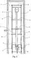
- Fig. 1 shows the upper end of an elevator shaft in side view. Of the elevator and shaft equipment, only the essential, most important elements with regard to the invention are shown.
- the elevator car 1 together with the car frame moves along vertical guide rails 2 which are fixed to the bottom of the shaft.
- the guide rails are secured to a shaft wall by means of rail fixing brackets 8 placed at certain distances from each other.
- the hydraulic cylinder 5 is immovably mounted directly on the elevator guide rails 2 by means of a cylinder supporter 7 provided with a projecting base 4 carrying the cylinder.
- This solution obviates the need for a separate supporting pillar, which, normally extending from the lower end of the hydraulic cylinder to the bottom of the shaft, would be very long and expensive.
- the cylinder supporter 7 is attached to the guide rails by means of rail clips and bolts 15. The cylinder force is transmitted by the guide rails to the bottom of the shaft.
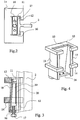
- holding devices 3 As illustrated by Fig. 2-4 are used.
- the frame of the holding device which consists of a hollow wedge-shaped socket 10, 11 tapering upwards, reinforcements 13, 14 bracing the socket and a supporting bar 16 at the lower end of the socket, is placed around the back of the guide rail 2 so as to leave a free space for the elevator between the guide rails.
- the frame and the reinforcements 13, 14 are open on the side facing towards the guide rail, so that, as the back of the guide rail is inside the frame of the holding device, the guiding part of the rail remains outside.
- the frame has essentially the shape of a rectangular letter C in which the inclined back wall 10 is perpendicular to each of the straight side walls 11 at the edges.
- the two front walls Starting at the front edge of each side wall there is a narrow front wall 12 in a position slightly turned out, the two front walls being essentially directed towards each other.
- the front walls are not exactly perpendicular to the side walls, but the slant of the front walls corresponds to the slant of the back of the guide rail.
- the opening of the C-shaped frame said opening extending through the whole height of the frame, through which opening the guiding part of the guide rail protrudes from inside the frame of the holding device.
- the supporting bar 16 at the bottom of the holding device, which connects the two side walls 11, is provided at its middle with a threaded hole for a tightening screw 17. Moreover, on each side of the threaded hole there is one unthreaded hole for screws 18 for releasing the wedge 19.
- the wedge 19 placed inside the frame of the holding device is correspondingly provided with threaded holes for the release screws.
- the wedge 19 itself is a body of a width nearly equal to the width of the space inside the frame, tapering upwards in its lateral dimension. The wedge is mounted between the slanting back wall 10 of the frame and the rear surface of the back of the guide rail.
- the straight front surface of the wedge which is pressed against the rear surface of the back of the guide rail, is provided with two parallel cutouts, each accommodating a serrated arrester 40 designed to increase the friction.
- the downward directed serrations of the arrester are pressed against the rear surface of the back of the guide rail when the wedge is tightened in place by means of the tightening screw 17.
- One holding device 3 is provided for each guide rail. After the holding devices have been slid onto the guide rail from the end of the rail and tightened on the guide rails and after the rails have been mounted in place, the cylinder supporter 7 can be lowered onto the holding devices. If the force applied to the cylinder supporter exceeds the hold power produced by the wedge and arrester 20, the cylinder supporter will tend to sink, thus driving the wedge deeper into the wedge socket formed by the frame of the holding device and correspondingly increasing the hold power as the pressure against the rear surface of the back of the guide rail increases.
- the cylinder itself is fixed with screws onto the projecting base 4 of the cylinder supporter.
- the wedge is released from its tightened condition by means of the release screws 18.
- This solution makes it easy to mount the cylinder steplessly at the correct height in the elevator shaft and obviates the need for a separate supporting pillar as mentioned above.
- the cylinder is secured by means of a band 9 or equivalent which in turn is fastened to the guide rails in the same way as the rail fixing brackets 8.
- the wedge need not necessarily be provided with cutouts and separate arresters 20, but the front surface of the wedge can be directly machined to form a hardenable scoring or serration to achieve the required hold power.
- the holding device can be so shaped on its side facing towards the guide rail that the holding devices can be reeved onto the rail from the side of the rail after installation of the guide rails.
Landscapes
- Engineering & Computer Science (AREA)
- Automation & Control Theory (AREA)
- Structural Engineering (AREA)
- Lift-Guide Devices, And Elevator Ropes And Cables (AREA)
- Types And Forms Of Lifts (AREA)
Applications Claiming Priority (2)
| Application Number | Priority Date | Filing Date | Title |
|---|---|---|---|
| FI942821 | 1994-06-14 | ||
| FI942821A FI100792B (fi) | 1994-06-14 | 1994-06-14 | Hissin hydraulisylinterin ripustusjärjestely |
Publications (3)
| Publication Number | Publication Date |
|---|---|
| EP0687645A2 true EP0687645A2 (de) | 1995-12-20 |
| EP0687645A3 EP0687645A3 (de) | 1996-07-31 |
| EP0687645B1 EP0687645B1 (de) | 2002-02-06 |
Family
ID=8540915
Family Applications (1)
| Application Number | Title | Priority Date | Filing Date |
|---|---|---|---|
| EP95109095A Expired - Lifetime EP0687645B1 (de) | 1994-06-14 | 1995-06-13 | Einbaueinrichtung eines Hydraulikzylinders für Aufzug |
Country Status (3)
| Country | Link |
|---|---|
| EP (1) | EP0687645B1 (de) |
| DE (1) | DE69525286T2 (de) |
| FI (1) | FI100792B (de) |
Cited By (1)
| Publication number | Priority date | Publication date | Assignee | Title |
|---|---|---|---|---|
| US10906780B2 (en) | 2015-07-27 | 2021-02-02 | Otis Elevator Company | Absorber for elevator system rail |
Family Cites Families (3)
| Publication number | Priority date | Publication date | Assignee | Title |
|---|---|---|---|---|
| DE1531106A1 (de) * | 1967-08-10 | 1969-08-07 | Haushahn Maschinenfabrik C | Hydraulisch betriebener Aufzug |
| GB1438727A (en) * | 1973-12-10 | 1976-06-09 | Sims A F | Hydraulically operated building hoist |
| JPS63106289A (ja) * | 1986-10-22 | 1988-05-11 | 株式会社日立製作所 | 流体圧エレベ−タ |
-
1994
- 1994-06-14 FI FI942821A patent/FI100792B/fi not_active IP Right Cessation
-
1995
- 1995-06-13 EP EP95109095A patent/EP0687645B1/de not_active Expired - Lifetime
- 1995-06-13 DE DE69525286T patent/DE69525286T2/de not_active Expired - Lifetime
Non-Patent Citations (1)
| Title |
|---|
| None |
Cited By (1)
| Publication number | Priority date | Publication date | Assignee | Title |
|---|---|---|---|---|
| US10906780B2 (en) | 2015-07-27 | 2021-02-02 | Otis Elevator Company | Absorber for elevator system rail |
Also Published As
| Publication number | Publication date |
|---|---|
| FI942821A0 (fi) | 1994-06-14 |
| FI942821L (fi) | 1995-12-15 |
| EP0687645A3 (de) | 1996-07-31 |
| FI100792B (fi) | 1998-02-27 |
| DE69525286T2 (de) | 2002-08-14 |
| DE69525286D1 (de) | 2002-03-21 |
| EP0687645B1 (de) | 2002-02-06 |
Similar Documents
| Publication | Publication Date | Title |
|---|---|---|
| US7165656B2 (en) | Elevator and guide fixing bracket for an elevator | |
| US7272886B2 (en) | Bearing press support adaptor | |
| EP0687644B1 (de) | Aufhängevorrichtung eines hydraulischen Aufzugs | |
| EP0687645A2 (de) | Einbaueinrichtung eines Hydraulikzylinders für Aufzug | |
| CA2260416A1 (en) | Connecting element for elevator guide rail | |
| GB2346408B (en) | Safety line anchor | |
| US4560131A (en) | Anchor stand | |
| US4916793A (en) | Straightening of unibody frames | |
| US12208990B2 (en) | Rail fastening device for guide rail sections of an escalator or moving walkway | |
| JP4034638B2 (ja) | エレベータの乗りかご保持装置 | |
| CN218624815U (zh) | 一种举升油缸后盖的安装结构 | |
| JP2004189366A (ja) | エレベータのつり合いおもり | |
| AU759605B2 (en) | Bearing press height extension adaptor | |
| CN212292420U (zh) | 一种稳定性好的电梯导轨连接结构 | |
| CN219730232U (zh) | 一种电梯轿顶安装固定支架 | |
| US6276187B1 (en) | Hydra clamp | |
| JPH05178570A (ja) | エレベータの乗場ドア装置 | |
| US4175420A (en) | Safety tie down for a pulling apparatus | |
| CN210313034U (zh) | 一种电梯导轨调节固定装置 | |
| AU2003209853B2 (en) | Bearing press support adaptor | |
| US5694805A (en) | Travelling clamp with removable rails | |
| US5189898A (en) | Heavy duty auxiliary tower for a repair rack | |
| SU449888A1 (ru) | Приспособление дл креплени полых огнеупорных брусьев к металлическому корпусу ванны | |
| KR200271462Y1 (ko) | 엘리베이터의 가이드레일 고정장치 | |
| JPH0525795B2 (de) |
Legal Events
| Date | Code | Title | Description |
|---|---|---|---|
| PUAI | Public reference made under article 153(3) epc to a published international application that has entered the european phase |
Free format text: ORIGINAL CODE: 0009012 |
|
| AK | Designated contracting states |
Kind code of ref document: A2 Designated state(s): DE FR IT SE |
|
| PUAL | Search report despatched |
Free format text: ORIGINAL CODE: 0009013 |
|
| AK | Designated contracting states |
Kind code of ref document: A3 Designated state(s): DE FR IT SE |
|
| 17P | Request for examination filed |
Effective date: 19970131 |
|
| R17P | Request for examination filed (corrected) |
Effective date: 19970131 |
|
| RAP1 | Party data changed (applicant data changed or rights of an application transferred) |
Owner name: KONE CORPORATION |
|
| 17Q | First examination report despatched |
Effective date: 19991228 |
|
| GRAG | Despatch of communication of intention to grant |
Free format text: ORIGINAL CODE: EPIDOS AGRA |
|
| GRAG | Despatch of communication of intention to grant |
Free format text: ORIGINAL CODE: EPIDOS AGRA |
|
| GRAH | Despatch of communication of intention to grant a patent |
Free format text: ORIGINAL CODE: EPIDOS IGRA |
|
| GRAH | Despatch of communication of intention to grant a patent |
Free format text: ORIGINAL CODE: EPIDOS IGRA |
|
| GRAA | (expected) grant |
Free format text: ORIGINAL CODE: 0009210 |
|
| AK | Designated contracting states |
Kind code of ref document: B1 Designated state(s): DE FR IT SE |
|
| REF | Corresponds to: |
Ref document number: 69525286 Country of ref document: DE Date of ref document: 20020321 |
|
| ET | Fr: translation filed | ||
| PLBE | No opposition filed within time limit |
Free format text: ORIGINAL CODE: 0009261 |
|
| STAA | Information on the status of an ep patent application or granted ep patent |
Free format text: STATUS: NO OPPOSITION FILED WITHIN TIME LIMIT |
|
| 26N | No opposition filed |
Effective date: 20021107 |
|
| PGFP | Annual fee paid to national office [announced via postgrant information from national office to epo] |
Ref country code: SE Payment date: 20140618 Year of fee payment: 20 Ref country code: DE Payment date: 20140619 Year of fee payment: 20 |
|
| PGFP | Annual fee paid to national office [announced via postgrant information from national office to epo] |
Ref country code: FR Payment date: 20140619 Year of fee payment: 20 |
|
| PGFP | Annual fee paid to national office [announced via postgrant information from national office to epo] |
Ref country code: IT Payment date: 20140630 Year of fee payment: 20 |
|
| REG | Reference to a national code |
Ref country code: DE Ref legal event code: R071 Ref document number: 69525286 Country of ref document: DE |
|
| REG | Reference to a national code |
Ref country code: SE Ref legal event code: EUG |